Protege PRT-PXS16 User manual

Standard 16 PGM Output Expander
PRT-PXS16
Installation Manual
1.0 Introduction
The Protégé System is an advanced technology security
system specifically designed to enhance the functionality
of security, building automation and access control by
providing a complete integrated solution with local
monitoring and offsite communication.
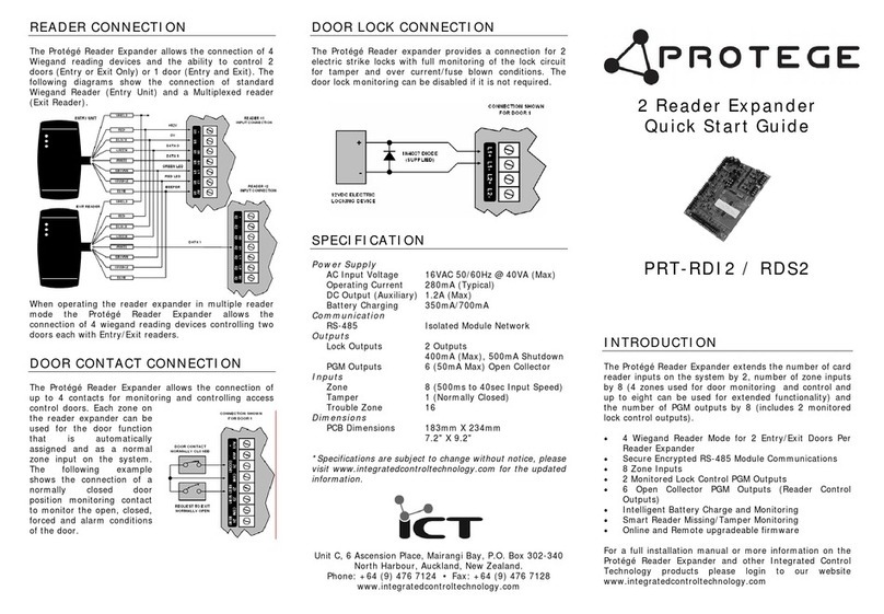
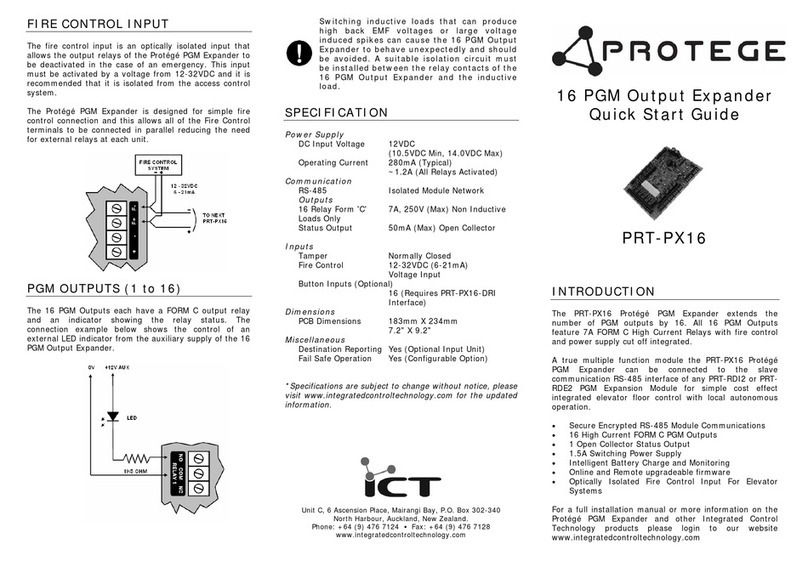
The Standard 16 PGM Output Expander allows the
expansion of the protégé system by 16 open collector
transistor outputs.
2.0 Configuration
The Standard 16 PGM Output Expander must be
configured with an address before it will communicate with
the Protégé System.
Device Address
The switch positions 1 to 7 select the device address from
1 to 128. When setting an address the Standard 16 PGM
Output Expander must be powered down and restarted for
the new address to take affect.
When changing the address the Standard 16 PGM Output
Expander will automatically default the internal
configuration and require a network update. See the
Protégé System reference manual for information on
performing a module update.
Figure 1 - Configuration Switch Settings
The configuration switch image on the right
shows the address setting for device address
008. The configuration switch on the left
shows address 001 (Default).
3.0 Communication
Support for up to 128 PGM expanders per system
controller is provided. The Protégé System uses a high
speed encrypted RS-485 communication interface.
Figure 2 - Network Communications
4.0 End Of Line Termination (EOL)
The end of line (EOL) jumper should be ON when the
Standard 16 PGM Output Expander is located at the start
or end of the module network.
Figure 2 - EOL Jumper Settings
Figure 3 - EOL ON Figure 4 - EOL OFF
5.0 Zone Input
The Standard 16 PGM Output Expander does not have any
provision for interfacing to zone input devices. For
expansion of zone inputs in the Protégé System refer to
the PRT-ZXS16 and PRT-ZX16 installation manuals.
6.0 Programmable Output
A PGM is a programmable output that can be activated
and deactivated based on specific events or functions
within the Protégé System. The primary function of the
Standard 16 PGM Output Expander is to activate any one
of the 16 onboard PGM outputs.
PGM Function
PXXXX:01 P1 Open Collector PGM Output.
PXXXX:02 P2 Open Collector PGM Output.
PXXXX:03 P3 Open Collector PGM Output.
PXXXX:04 P4 Open Collector PGM Output.
PXXXX:05 P5 Open Collector PGM Output.
PXXXX:06 P6 Open Collector PGM Output.
PXXXX:07 P7 Open Collector PGM Output.
PXXXX:08 P8 Open Collector PGM Output.
PXXXX:09 P9 Open Collector PGM Output.
PXXXX:10 P10 Open Collector PGM Output.
PXXXX:11 P11 Open Collector PGM Output.
PXXXX:12 P12 Open Collector PGM Output.
PXXXX:13 P13 Open Collector PGM Output.
PXXXX:14 P14 Open Collector PGM Output.
PXXXX:15 P15 Open Collector PGM Output.
PXXXX:16 P16 Open Collector PGM Output.

7.0 Trouble Zone Input
Trouble zones are used to monitor the status of the
Standard 16 PGM Output Expander and in most cases not
physically connected to the an external zone. An example
is trouble zone 8 is the communication trouble zone, this
will open when the Standard 16 PGM Output Expander is
removed from the system or has lost communication.
Trouble Zone Function
PXXXX:01 Tamper Input. Normally Closed
Contact.
PXXXX:02 Power Fault. Power to the Standard
16 PGM Output Expander is below
10.5VDC.
PXXXX:03 Reserved.
PXXXX:04 Reserved.
PXXXX:05 Reserved.
PXXXX:06 Reserved.
PXXXX:07 Reserved.
PXXXX:08 Device Communication. The
Standard 16 PGM Output Expander
has lost communications and is no
longer online with the Protégé
System Controller.
8.0 Error Messages
When the Standard 16 PGM Output Expander is powered
up and starts communicating with the controller it is
possible that the Standard 16 PGM Output Expander can
be denied access to the module network. This is a normal
part of the Protégé System.
In normal operation the status indicator will flash rapidly
while it is attempting to contact the controller. When it is
online it will turn flash at one second intervals. When an
error occurs the status indicator will FLASH with the error
code number. The error code number is shown with a
250ms ON and OFF period (duty cycle) with a delay of 1.5
seconds between each display cycle.
1 Flash - Internal Error
An internal error has occurred on the Standard 16 PGM
Output Expander. Please contact your distributor.
2 Flash - Version Error
The version of the Standard 16 PGM Output Expander is
not correct for the System Controller. The firmware can be
updated. Please contact your distributor.
3 Flash - Keypad Address Too High
The address of the Standard 16 PGM Output Expander that
is programmed is beyond the maximum number of
Standard 16 PGM Output Expander that are allowed to
connect to the system controller. You may also be able to
adjust the controller profile to increase the Standard 16
PGM Output Expander module capacity.
4 Flash - Duplicate Device Address
The address of the Standard 16 PGM Output Expander is
already programmed in to the address location.
5 Flash - Security Violation
The system controller has security enabled and no devices
can be added to the system.
6 Flash - Invalid Serial Number
The Standard 16 PGM Output Expander has an invalid
serial number programmed and can not be registered on
the system. Return the Standard 16 PGM Output Expander
to your distributor.
9.0 Specifications
Power Supply
Voltage 12VDC (10.5 - 14.0VDC)
Current 59mA (Typical)
Communication
RS-485 Module Network
Outputs
PGM Output 16 (50mA Max) Open Collector
Inputs
Tamper 1 (Normally Closed Contact)
Trouble Zone 8
Temperature
Operating 5˚- 55˚Celsius
41˚- 131˚Fahrenheit
Humidity 0%-85% (Non-Condensing)
*Specifications are subject to change without notice,
please visit www.integratedcontroltechnology.com for the
updated information.
Other Protege Extender manuals

