Protel Elite Series User manual

®
Smart Payphone
User’s Guide

This page intentionally left blank

Elite Series User’s Guide i
Proprietary and Confidential
Table of Contents
Notices v
Warranty v
Repair.................................................................................................................................................... v
Safety Information.................................................................................................................................vi
Quality Assurance and Reliability....................................................................................................vi
Environmental Requirements ..........................................................................................................vi
Nickel-Cadmium (Ni-Cd) Battery......................................................................................................vi
Introduction 1
Introducing the Elite Series...................................................................................................................1
General Description ..............................................................................................................................2
Elite Series Product Line.......................................................................................................................2
EL1000.............................................................................................................................................2
EL1200.............................................................................................................................................2
EL1230 Standard Display................................................................................................................2
EL1230 CARTE Display...................................................................................................................2
EL1230 VF Display..........................................................................................................................3
EXC Models..................................................................................................................................... 3
EL1260.............................................................................................................................................3
Components 3
Elite Payphone Housing........................................................................................................................3
Construction of the Elite payphone.......................................................................................................3
Internal Parts of the Elite.......................................................................................................................4
Lower Housing Components.................................................................................................................5
Coin Box w/Lid ......................................................................................................................................6
Vault Door .............................................................................................................................................6
Vault Door Lock.....................................................................................................................................6
Coin Box Alarm Switch..........................................................................................................................6
Terminal Block ......................................................................................................................................6
Flash Electronic Chassis.......................................................................................................................6
Coin Scanners.......................................................................................................................................6
Electronic coin Scanner - ECS IIB...................................................................................................6
Medallist Coin Scanner....................................................................................................................7
Electronic Coin Scanner - ECS V ....................................................................................................7
Dual Solenoid Relay/Hopper and coin Return Chute Assembly...........................................................7
Upper Housing Components 7
Locking Bars .........................................................................................................................................7
Hookswitch Assembly...........................................................................................................................7
Upper Housing Lock.............................................................................................................................. 7
Coin Entrance ....................................................................................................................................... 8
Coin Release Push Button....................................................................................................................8
Handset.................................................................................................................................................8
Hookswitch Plate...................................................................................................................................8

ii Elite Series User’s Guide
Proprietary and Confidential
Top Piece.............................................................................................................................................. 9
Main Bezel.............................................................................................................................................9
Dial Key Components ...........................................................................................................................9
Upper Housing Interconnect Cable....................................................................................................... 9
Information Card ................................................................................................................................... 9
Hookswitch Cradle................................................................................................................................9
Cast Aluminum Backing Plate.............................................................................................................10
Function Key Components.................................................................................................................. 10
Redial Button ................................................................................................................................. 10
Up/Down Volume Control ..............................................................................................................10
New Call Button .............................................................................................................................10
Multi-function Buttons..........................................................................................................................11
Language Select button.................................................................................................................11
Change Card button.......................................................................................................................11
Speed Dial buttons.........................................................................................................................11
Displays...............................................................................................................................................11
Card Reader (EL1200, 1230 & 1260 only)..........................................................................................12
Display Controller Board.....................................................................................................................12
Mounting the Payphone 13
Mounting Location...............................................................................................................................13
Leveling the Mounting Surface ...........................................................................................................13
Mounting the Backboard.....................................................................................................................14
Separating the Upper and Lower Housings........................................................................................14
Removing the Coin Scanner...............................................................................................................15
Removing the Chassis Assembly .......................................................................................................15
Removing the Coin Box ......................................................................................................................15
Installing the Security Studs................................................................................................................16
Securing the Payphone to the Mounting Surface ...............................................................................16
Reinstalling the Coin Box.................................................................................................................... 17
Reinstalling the Chassis Assembly.....................................................................................................17
Reinstalling the Coin Scanner.............................................................................................................17
Connecting the Line Wire to the Terminal Block.................................................................................18
Connecting the External DC Power (VFD models only).....................................................................18
Connecting the Upper and Lower Housings Together........................................................................19
Appendix A –FLASH Chassis 20
FLASH Chassis Exploded View..........................................................................................................21
Appendix B –EL1000 Initialization and Programming 22
Introduction..........................................................................................................................................22
Basic Key Terms:...........................................................................................................................22
Initialization Procedure Basic Steps: .............................................................................................22
Initialization and Local Programming for the EL1000 .........................................................................22
Entering the programming mode...................................................................................................23
Programming Rules.......................................................................................................................23
EL1000 Programming Chart ...............................................................................................................24
Programming Steps Outlined..............................................................................................................25
Features Programming.................................................................................................................. 25
Default programming .....................................................................................................................28
Resetting the Chassis to Error #7.................................................................................................. 29

Elite Series User’s Guide iii
Proprietary and Confidential
Program the Real Time Clock........................................................................................................29
Diagnostics Codes.........................................................................................................................30
Call the Management System (ProNet).........................................................................................30
Appendix C –EL1200, 1230 or 1260 Initialization and Programming 31
Introduction..........................................................................................................................................31
Basic Key Terms:...........................................................................................................................31
Initialization Procedure Basic Steps: .............................................................................................31
Initialization and Local Programming for the EL1200, 1230 or 1260 payphones...............................31
Entering the programming mode...................................................................................................31
Selection #1 –Programming...............................................................................................................32
Selection #2 –Call Management System...........................................................................................35
Selection # 3 –Diagnostics.................................................................................................................35
Selection #4 –Utilities......................................................................................................................... 35
Payphone reporting modes.................................................................................................................37
Coin box Collect.................................................................................................................................. 37
Console Programming Chart...............................................................................................................38
Appendix D - Programming of Messages for a Standard, CARTE and VF displays 39
Appendix E –Operational Test Procedure 40
Operational Tests................................................................................................................................40
Appendix F –Error Messages 41
Appendix G –Spare Parts List 42
Spare Parts List (cont’d.).....................................................................................................................43
Appendix H –Return Procedures for Parts in and/or out of Warranty 44
CRN –Customer Return Number –External Procedure....................................................................44
Part I- Requesting the return for repair of parts or equipment.......................................................44
Part II –Receipt of Material at Protel.............................................................................................45
Part III –Shipping ..........................................................................................................................45
Appendix I –Information Card Removal, Installation, and Specifications 46
Removal of the Information Card........................................................................................................46
Installation of the Information Card.....................................................................................................47
EL1000 Information Card Dimensions................................................................................................47
Multi-function Buttons and Display Dimensions..................................................................................48
Multi-function buttons Label Dimensions............................................................................................48
Appendix J –Handset Replacement and Jumper Settings 49
Replacing the Handset........................................................................................................................49
Handset Jumper Settings....................................................................................................................50
Handset Jumpers inside the Upper Housing.................................................................................50
Handset Jumper on Chassis Assembly......................................................................................... 50

iv Elite Series User’s Guide
Proprietary and Confidential
Appendix K –Specifications 51
Electrical..............................................................................................................................................51
Hardware.............................................................................................................................................51
Appendix L –Regulatory Information 52
FCC Registration.................................................................................................................................52

Elite Series User’s Guide v
Proprietary and Confidential
Notices
Before using your Elite®smart payphone, be sure to read the general safety information
on the next page.
Elite®, ProNet®, and Protel®are registered trademarks of Protel, Incorporated.
Abloy®is a registered trademark of Abloy Security, Inc. Coinco®is a registered
trademark of Coin Acceptors, Inc. Medeco®is a registered trademark of Medeco
Security Locks, Inc. All other trademarks are those of their respective companies and are
hereby acknowledged.
This publication could include technical inaccuracies or typographical errors. Changes
are periodically made to the information herein; these changes will be incorporated in
new editions of the publication. Protel may make improvements or changes in the
products described in this publication at any time.
Warranty
PROTEL, INC. (PROTEL) warrants that all products that it manufactures shall operate in
accordance with published specifications. Products shall be free from defects in material
and workmanship for the warranty period, which begins on the date of shipment.
THE LIMITED WARRANTY EXPRESSED HEREIN IS THE SOLE AND EXCLUSIVE
WARRANTY PROVIDED BY PROTEL. PROTEL MAKES NO OTHER WARRANTY,
EITHER EXPRESSED OR IMPLIED, OF ANY KIND INCLUDING WITHOUT
LIMITATION ANYWARRANTY OR MERCHANTABILITY, FITNESS FOR A
PARTICULAR PURPOSE, TITLE OR LACK OF INFRINGEMENT.
THE CORRECTION OF ANY DEFECTS BY REPAIR OR REPLACEMENT WITHIN THE
WARRANTY PERIOD SHALL CONSTITUTE THE SOLE AND EXCLUSIVE REMEDY
OF PURCHASER AND SHALL CONSTITUTE THE FULFILLMENT OF THE ENTIRE
OBLIGATION OF PROTEL WITH RESPECT TO ANY WARRANTY GIVEN HEREIN.
PROTEL SHALL NOT BE LIABLE TO PURCHASER OR ANY THIRD PARTY FOR
LOSS OF PROFITS, DIRECT, INDIRECT, SPECIAL OR CONSEQUENTIAL, OR
OTHER DAMAGES FROM ANY CAUSE WHATSOEVER.
Repair
Protel, Inc. will repair or replace any product of its manufacture. All requests for such
repair should be directed to Protel International’s Customer Service Department (863)
freight prepaid. Out-of-warranty repair is handled on a labor-plus-parts basis. Please
see Appendix H for more information on Protel’s CRN procedure for repairs in and out of
warranty.

vi Elite Series User’s Guide
Proprietary and Confidential
Safety Information
Quality Assurance and Reliability
Product integrity shall be maintained and there shall be no deviations from physical
criteria that may or will adversely affect the product with respect to safety, reliability,
interchangeability, life, performance and operation, quality, protectants, maintenance or
aesthetics.
The manufacturing processes, tests and inspection procedures, and quality program
used by a manufacturer shall be adequate to provide that technical requirements and
customer endpoint requirements are met. Quality Assurance criteria are met in this area
to cover the ability of the factory testing program to provide product operability and
functionality. Details of the quality program criteria are documented in the procedures
governed by International Standards. Products shall be manufactured in accordance with
the following:
ISO 9001 International Standards
Federal Communications Commission (FCC) Requirements
Occupational Safety and Health Standards (OSHA)
All other applicable Federal, State and local requirements consistent with industry
standards.
Environmental Requirements
Toxic materials appearing on lists of banned or dangerous materials issued by
appropriate government agencies pertaining to devices, components etc., shall not be
used in the manufacture of the payphone.
Nickel-Cadmium (Ni-Cd) Battery
Here are some suggestions on Ni-Cd Battery handling:
Hazardous Waste Disposal: - Nickel Cadmium Battery upon replacement should not be
opened or incinerated. Recycling of the units are recommended.
Storage: - Store in a cool place. This will prevent condensation on the individual 1.2V
cells or battery terminals.
Handling: - Accidental short circuit will bring high temperature elevation to the battery as
well as shorten the battery life. Be sure to avoid prolonged short circuit since the heat
can burn attendant skin and cause rupture.

Elite Series User’s Guide vii
Proprietary and Confidential
This page intentionally left blank

Elite Series User’s Guide 1
Proprietary and Confidential
Introduction
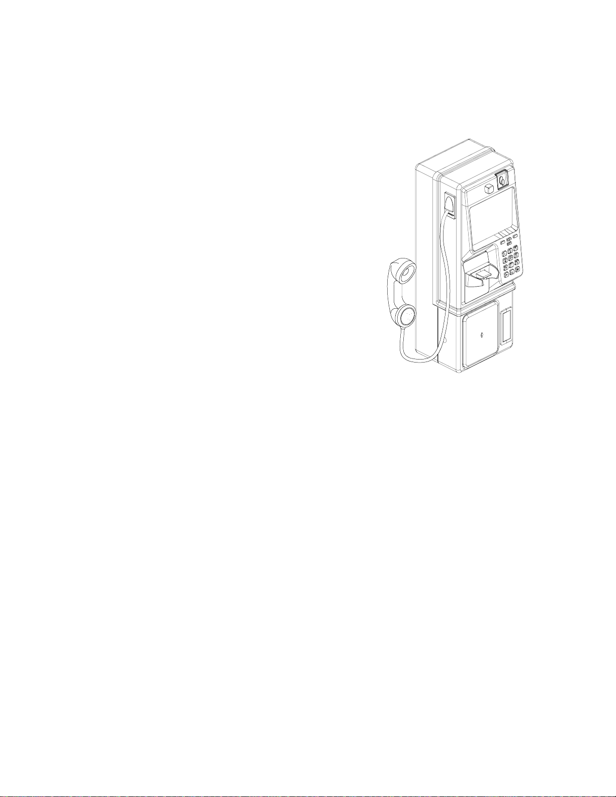
Introducing the Elite Series
Protel’s revolutionary Elite smart payphone
boasts that rare feat of combining truly exquisite
form with superior function. Rising above the
ordinary to reach new heights, Elite’sclean lines
and ergonomic layout make it the perfect
payphone to install at any location. City
sidewalks, retail stores, malls, hotel chains,
airports, restaurants, convention centers, colleges
and hospitals are all potential sites that allow you
to reap the benefits of installing Elite. Its sleek,
sophisticated appearance is the ticket to getting
into more locations, as well as keeping existing
location owners happy.
Elite is designed for ultimate flexibility. It can be
site specific, location specific, account specific or
customer specific. This payphone goes
anywhere.
In addition to attracting traditional callers paying
with coins, Elite’s optional state-of-the-art card
readers encourage use by callers who demand
the benefits of the latest technology.
Intuitive operation is expected from today’s payphones and that’s what is delivered with
Elite. Icons gently guide users with a minimum of direct instruction. Strategically placed
feature buttons allow language selection, receiver volume control and next-call function
through visual instructions. Larger, wider spaced keys make dialing easier for everyone,
especially those with vision impairment or a limited range of hand motion.
The Elite’s high strength steel housing provides maximum security and resistance to
corrosion, maintaining its good looks through out a lifetime of excellent service. A
scratch-resistant, polyester powdercoat finish gives the Elite a look to appreciate. O-ring
seals resist water to give the Elite a long and reliable service life. All of these features
translate into more satisfied customers.
The Elite payphone is rising to a new level of style, flexibility, durability and user
satisfaction.
Basic Elite

2Elite Series User’s Guide
Proprietary and Confidential
General Description
The feature package of the Elite Series is provided by station-
based intelligence that is compatible with all types of central
offices. The Elite permits basic coin service, as well as the use
of magnetic stripe cards with an insertion-type card reader.
The same reader accepts a variety of memory and, optionally,
smart cards.
Elite payphones are compatible with many of Protel’s products
with respect to coin scanners, locks, vault doors, coin box
switches, and handsets. Re-dial, Up/Down volume control,
and Next Call buttons are standard for Elite models.
Elite payphones are modular in design. This allows Protel
International to offer several payphone models so the
customer can chose which one is best for their operation.
Features offered include card reading devices, multifunction
buttons, and displays. See the following section for more
information on the Elite’s product line.
Elite Series Product Line
Elite Series payphones are flexible when accepting coins. The Elite Series standard
version payphones will accept coins up to 27 mm in diameter, while the EXC Models will
accept coins up to 33 mm in diameter. See the brief descriptions below.
EL1000
This is our Voice/Coin only payphone. It features voice prompts for user instructions or
advertising.
EL1200
This is our Display/Coin only payphone. The display can be Standard, CARTE, or
Vacuum Fluorescent. Each type is described in the sub-sections that follow.
EL1230 Standard Display
This is our full-featured payphone with an LCD display capable of supporting the
standard ASCII character set, thus being able to display messages in five basic
downloadable languages i. e.: English, Spanish, French, German, Portuguese. It also
features a dual card reader, which can read magnetic stripe cards as well as memory
cards and chip cards.
EL1230 CARTE Display
The main feature of this model is that its LCD display is capable of supporting ASCII and
non-ASCII characters, giving it the ability to display messages in a limited number of
languages. CARTE is an acronym phrase for Chinese, Arabic, Roman, Thai and
European.
Full-Featured Elite

Elite Series User’s Guide 3
Proprietary and Confidential
EL1230 VF Display
The main, and most distinguished feature of this model, is its Vacuum Fluorescent
display. Because it is externally powered, not only off-hook toggling and scrolling
messages can be displayed, but also, when it is on-hook.
EXC Models
All the models previously described can be ordered with an ECS V coin scanner, giving
them the ability to accept coins up to 33 mm in diameter and up to 3.3 mm in thickness.
This is what we call EXtended Coin capability.
EL1260
This is our card only payphone. It can be equipped with either of the display types
described before.
Components
Elite Payphone Housing
The Elite’s housing components are engineered and manufactured to improve on the
longevity and reliability of traditional payphone equipment. The Elite is a result of Protel’s
innovation, technology, and drive to create better products to fulfill your public
communication needs.
The Elite’s housing components are included in the warranty. The housing components
are backed by Protel’s one-year warranty.
Designed with the use of the latest 3D Computer Aided Design (CAD) software, the Elite
offers our valued customers benefits that include; increased component reliability,
extended life cycles, and greater resistance from vandalism and weather stresses. The
Elite telephone is designed to mount in panel mount style housings.
Construction of the Elite payphone
Elite housings consist of a two-piece cabinet shell constructed of 15 gauge (1.8 mm)
deep drawn 1006-carbon steel that contains welded reinforcing members. The primary
metalwork (deep draw) is accomplished on an 800-ton press. Extra-heavy 9-gauge steel
is used for the vault door, which also incorporates reinforcing members. In order to
reduce unauthorized access to the interior of the payphone, tongue-and-groove type
construction is used at the mating surfaces of the upper and lower housings and vault
door. Case-hardened inner plates, combat attempts to pry or drill into the housing
protecting the lower housing and vault door. An O-Ring type seal around the groove in
the Main Bezel and the hookswitch plate prevents water from coming inside the
payphone. All Elite housing components are 100% tested for proper form, fit, and
function as per ISO 9001 International Standards.

4Elite Series User’s Guide
Proprietary and Confidential
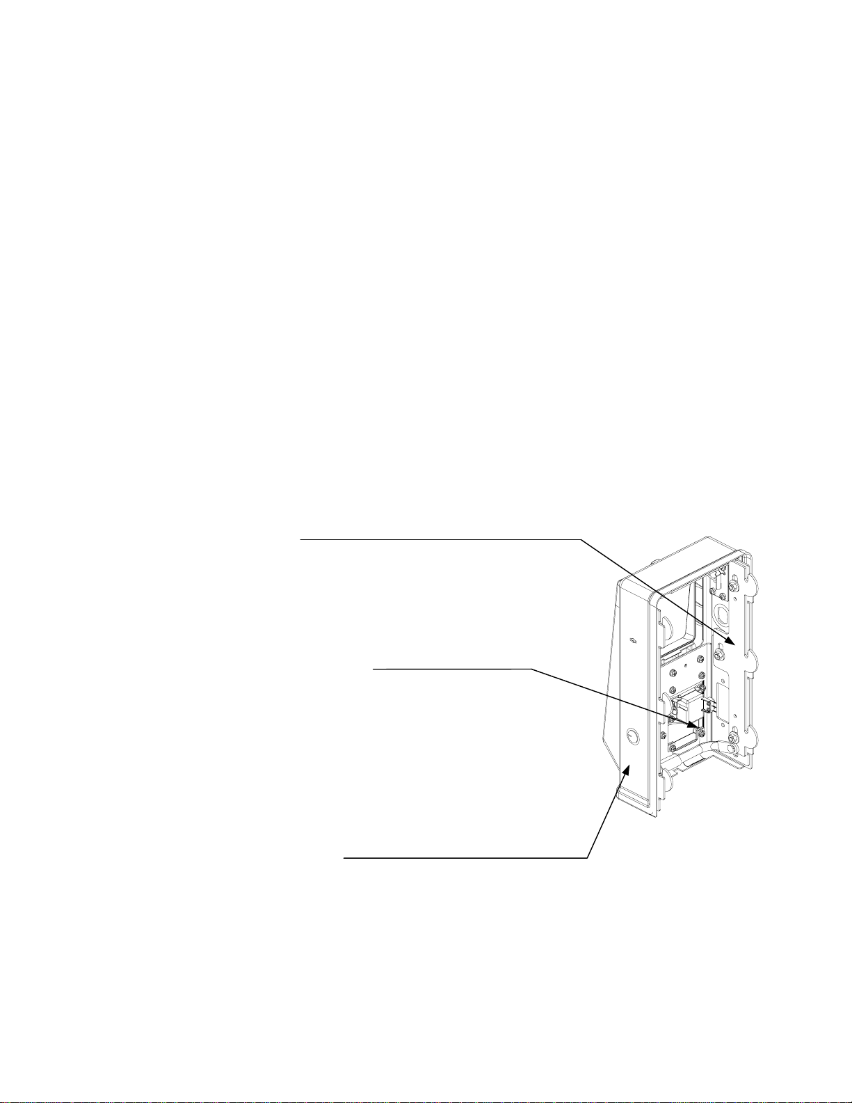
Internal Parts of the Elite
All Elite internal parts are also manufactured in accordance with ISO 9001 International
Standards. This section describes the components found in both the upper and lower
housing of the payphone. The figure below shows these two basic parts of the Elite
payphone.
Make sure that the end of the cable that is plugged into the upper
housing is positioned such that the red edge of the ribbon cable is
plugged into Pin 1 on connector P4.
Upper Housing
Interconnect
Cable

Elite Series User’s Guide 5
Proprietary and Confidential
Lower Housing Components
The following figure shows the main parts of the lower housing of the Elite payphone.
Then, a short description for each component follows.
Lower Housing
Dual Solenoid Relay/Hopper
Assembly
Coins up to
33 mm in
diameter Coins up to
27 mm in
diameter
Electronic Coin Scanners
ECS IIB Medallist ECS V
Coin Adapter
Chute for
ECS V
Coin Return
Chute for
Medallist
Coin Return
Chute for
ECS IIB and
ECS V
Coin Box
Alarm Switch
Vault Door
Lock
Vault Door
Coin Box
with Lid
Terminal
Block
FLASH
Chassis

6Elite Series User’s Guide
Proprietary and Confidential
Coin Box w/Lid
This is a standard coin box that is compatible with coins up to 27 mm in diameter. The
coin box is used to store the coins that are deposited into the payphone. Models with
EXtended Coin capability would require the lid with the wider top opening to accept coins
up to 33 mm in diameter.
Vault Door
The vault door is used to enclose the coin box in the telephone and is secured in place by
a four-point latching cam mechanism. The vault door latches (bolts) are hardened in
order to resist vandalism. The vault door mechanism is nickel-plated for maximum
corrosion protection. Vault doors are available in stainless steel matte finish or black.
Vault Door Lock
The vault door lock is used to lock the vault door in place. Medeco and Abloy are the
preferred manufacturers for these locks.
Coin Box Alarm Switch
A coin box alarm switch is installed to monitor removal of the coin box. Once the coin
box is removed, the payphone will prompt the collector to enter an ID code. Once
entered, the payphone will call ProNet and report the collector’s ID and the amount it had
when collected.
Terminal Block
The terminal block located inside the lower housing of the phone is used to provide tip &
ring connection to the electronic chassis assembly. It is also useful to measure line
voltage and current.
Flash Electronic Chassis
The Flash electronic chassis assembly contains the transmission network, coin-control
components and logic circuitry. A battery pack and a piezo-electric ringer are also
installed on the board. The payphone’s basic program is stored in a Flash memory
device. With Flash memory, the payphone can be reprogrammed when an update to the
basic program is needed. A program button is also provided which allows service
personnel to initialize and program the payphone for local operation, if necessary.
Coin Scanners
Electronic coin Scanner - ECS IIB
This kit consists of a simple molded plastic track and an option board for the chassis
which provides electronic coin identification and validation functions. The electronic coin
scanner, by default, will recognize only U.S. coins.
Elite Series User’s Guide 7
Proprietary and Confidential
Medallist Coin Scanner
This coin scanner is an enhancement of the ECS IIB, with the addition of a metal coin
entrance.
Electronic Coin Scanner - ECS V
This coin scanner is capable of accepting up to twelve different coin types of, almost, any
denomination. It can accept coin sizes up to 33 mm in diameter and up to 3.3 mm in
thickness. The coin data set can be remotely downloaded from ProNet to the coin
scanner via the coin option board.
Dual Solenoid Relay/Hopper and coin Return Chute Assembly
The dual solenoid relay/hopper and coin return chute assembly serve to relocate coins
that are held in the hopper as a result of a coin deposit. Each solenoid has a paddle
attached to it. The solenoid that receives the proper voltage polarity from the Flash
chassis will activate and open the paddle, making the payphone collect or refund the
coins.
Upper Housing Components
Locking Bars
Retention of the upper housing to the lower is effected
by two latching steel slide bars called Locking Bars that
secure at six points which are actuated by the T-
wrench. The T-wrench is a one-piece unit of hardened
stamped steel.
Hookswitch Assembly
The Elite incorporates a sealed hookswitch and an
external micro switch assembly that resists corrosion
and increases reliability. The micro switch also
increases the overall performance of the assembly by
having only the spring mechanism inside the
hookswitch, being the micro switch responsible of
sending the appropriate off-hook/on-hook signaling to
the chassis.
Upper Housing Lock
The upper housing lock secures the latch assembly in place, preventing its separation
from the lower housing.
8Elite Series User’s Guide
Proprietary and Confidential
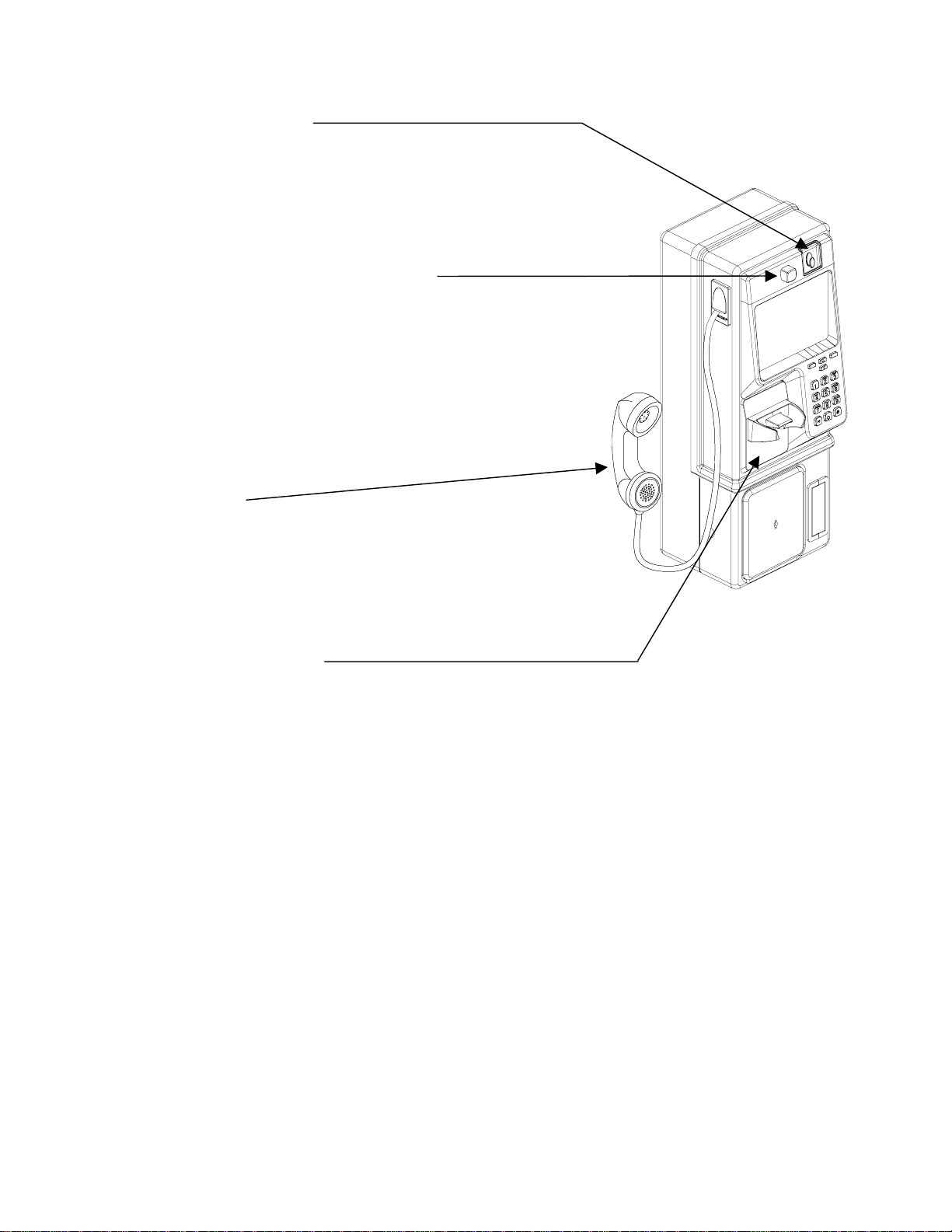
Coin Entrance
The coin entrance comes in two sizes, depending
on the payphone model. Standard size for coins up
to 27 mm in diameter, or the EXC (Extended Coin
capability) type, which accepts larger coins up to
33mm in diameter.
Coin Release Push Button
The coin release push button, when pushed,
causes the payphone to release a jammed
deposited coin. Only those coins that have not yet
been sent into the hopper will be returned to the
customer. Coins already sent to the hopper will be
returned when the handset is returned to the
cradle. The coin return linkage is a stainless steel
assembly that is compatible with industry standard
coin scanners.
Handset
Only Protel approved modular handsets should be
used in the Elite telephone. Do not assume that
any general handset will be compatible with the
Elite Telephone. Jumper settings for carbon or
dynamic handset operation can be found in
Appendix F of this document.
Hookswitch Plate
This cast aluminum cover provides mounting for the hookswitch cradle and hookswitch
assembly. This applies only to voice only models.
Elite Series User’s Guide 9
Proprietary and Confidential
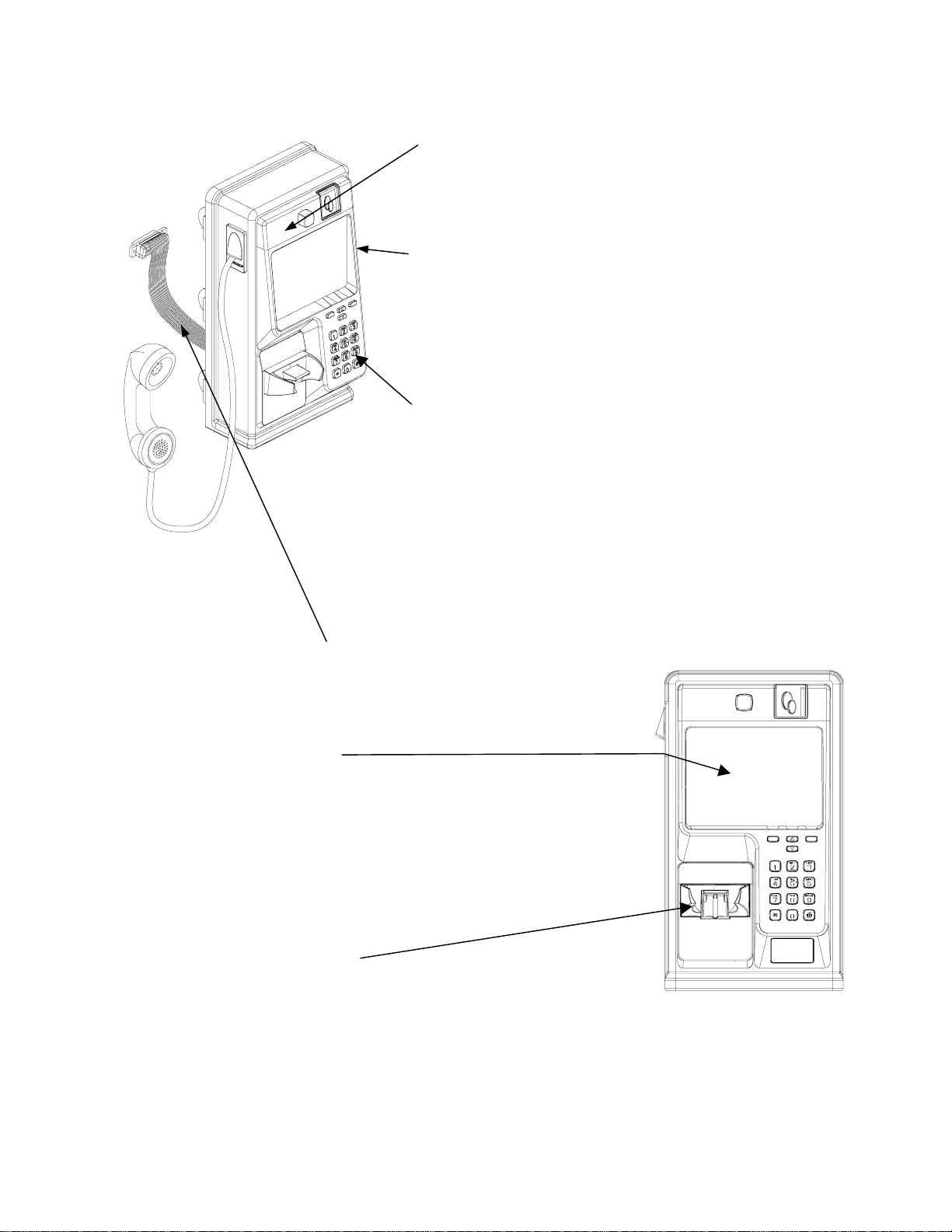
Top Piece
The top piece is located above the main bezel and contains
the coin entrance and coin return push button. Custom
logos can be designed and silk screened on the top piece.
Main Bezel
The main bezel of the telephone is a chromed, matte finish,
cast aluminum with a minimal wall thickness of 0.140". The
main bezel is securely fastened to the upper housing at six
points to provide strength against vandalism. Impact test
performed rated well above industry standards.
Dial Key Components
One of the main bezel components is the dial keypad. This
is an XY matrix printed circuit board that is securely
fastened to the back of the main bezel. Additionally, there
is a stainless steel push-button retainer plate behind the
dial keys to prevent over-travels and reduces vandalism.
The dial keys are ergonomically designed for greater
customer convenience. The push buttons are cast
aluminum, and are also designed to prevent moisture from
entering the housing. The ’5’key has a raised pip to
provide assistance to vision-impaired persons.
Upper Housing Interconnect Cable
This ribbon cable connects the upper housing electronics
of the phone to the chassis in the lower housing.
Information Card
The large information card (4.84" x 6.28", approximately
30.4 sq. in.), which can contain printed instructions
determined by the customer, is protected with a clear
polycarbonate plastic cover and is reinforced within the
telephone by a cast aluminum backing plate.
Specifications and installation instructions for the
Information Card can be found in Appendix E of this
document.
Hookswitch Cradle
Standard GTE style. Easily replaced with four (4) screws.

10 Elite Series User’s Guide
Proprietary and Confidential
Cast Aluminum Backing Plate
The backing plate, which mounts inside the upper housing of the phone, provides support
to the information card and protects the phone against vandalism.
Function Key Components
The function keys consist of push-buttons, a push-button retainer plate, and a circuit
board. The function buttons enhance the use of the full-featured payphone by providing
redial, language selection and speed dial.
Redial Button
When pressing this button, the payphone will dial the last
number the user entered. This function will only be available
when the New Call button is pressed.
Up/Down Volume Control
The volume control is active any time the
phone is off hook. The payphone has three
audio levels that can be controlled with these
buttons. Pressing the up button will increase
the volume by one level. Pressing the down
button will decrease the volume by one level.
Pressing the up volume button will have no
effect if the volume level is already at
maximum. Pressing the down volume
button will have no effect if the volume level
is already at minimum.
New Call Button
Any time the New Call button is pressed, the payphone will relinquish the line and re-
seize it back again according the delay programmed in ProNet, offering dial tone again,
thus allowing the user to dial another call without hanging up and picking up the handset.
At this point, the user can, if necessary, make use of the Redial button. Keep in mind
that the payphone will retain the remaining credit from the previous call, if any.
This manual suits for next models
5
Table of contents
Other Protel Telephone manuals


