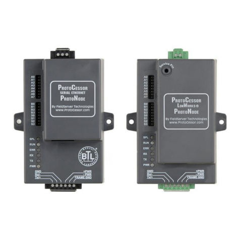
ProtoCessor ProtoNode RER User guide

Document Revision: 7
ProtoNode RER and ProtoNode LER
Startup Guide
For Interfacing Customer Product: Harsco Industrial Patterson-Kelley
ENVI Control Systems and Love Controller
To Building Automation Systems: BACnet MS/TP, BACnet IP, Metasys
N2, Modbus TCP, and LonWorks
APPLICABILITY & EFFECTIVITY
Explains the ProtoNode RER and LER hardware and how to install it.
The instructions are effective for the above as of March 2013

Harsco Industrial Patterson-Kelley ProtoNode Startup Guide Page 2 of 38
ProtoCessor 1991 Tarob Court Milpitas, California 95035 USA Web: www.protocessor.com
Tel: (408) 964 4444 Fax: (408) 964 4425 Toll Free: (800) 317 8319 email: support@protocessor.com
THIS PAGE INTENTIONALLY LEFT BLANK

Harsco Industrial Patterson-Kelley ProtoNode Startup Guide Page 3 of 38
ProtoCessor 1991 Tarob Court Milpitas, California 95035 USA Web: www.protocessor.com
Tel: (408) 964 4444 Fax: (408) 964 4425 Toll Free: (800) 317 8319 email: support@protocessor.com
TABLE OF CONTENTS
1Introduction ................................................................................................................................................... 5
1.1 BTL Mark –BACnet Testing Laboratory .........................................................................................................5
1.2 LonMark Certification ....................................................................................................................................5
2BACnet/LonWorks Setup for ProtoNode RER/LER.......................................................................................... 6
2.1 Installation steps for the customer................................................................................................................6
2.2 Record Identification Data .............................................................................................................................6
2.3 Configure the DIP Switches............................................................................................................................6
2.3.1 Setting the Node/ID Device Instance (DIP Switch A0 –A7) for BACnet MS/TP, BACnet/IP, and Metasys
N2 ……………………………………………………………………………………………………………………………………………………………6
2.3.2 Setting the Serial Baud Rate (DIP Switch B0 –B3) for BACnet MS/TP and Metasys N2 ProtoNodes.......7
2.3.3 Using S0 –S3 bank of DIP Switches to select and load Configuration Files for ENVI and Love Controller
……………………………………………………………………………………………………………………………………………………………7
3Interfacing the ProtoNode to ENVI and Love Controller ............................................................................... 10
3.1 ProtoNode RER and LER component layout with the cover removed.........................................................10
3.2 Wiring Connections to ProtoNode RER and LER for the ENVI and Love Controller .....................................11
3.2.1 Connecting ENVI Modbus RTU Boilers to the ProtoNode’s RS-485 ........................................................12
3.2.2 Biasing the Modbus RS-485 Network.....................................................................................................12
3.2.3 End of Line Termination Switch for the Modbus RS-485 port on the ProtoNode...................................13
3.3 Wiring the ProtoNode RER to RS-485 Field Protocol...................................................................................14
3.4 Wiring the ProtoNode LER Field Port to a LonWorks network ....................................................................15
3.5 Power-Up the ProtoNode RER or LER ..........................................................................................................15
4Commissioning the ProtoNode LER on a LonWorks network........................................................................ 16
4.1 Commissioning the ProtoNode LER on a LonWorks network......................................................................16
4.1.1 Instructions to Upload XIF File From the ProtoNode LER Using FS GUI Web Server ..............................16
5Connect the ProtoNode’s Web GUI to Setup IP Address for BACnet/IP or Modbus TCP ............................... 18
5.1 Connect the PC to the ProtoNode via the Ethernet port.............................................................................18
5.2 Use the ProtoNode Web GUI to Connect to the ProtoNode .......................................................................19
5.3 Set IP Address for BACnet/IP or Modbus TCP via GUI .................................................................................19
6Chipkin Automation’s CAS BACnet Explorer for validating the Protonode in the field on a BACnet MS/TP or
BACnet/IP network.............................................................................................................................................. 21
6.1 Downloading Chipkin Automation’s CAS Explorer and Requesting an Activation Key ................................21
6.2 CAS BACnet Setup........................................................................................................................................22
6.2.1 CAS BACnet MS/TP Setup.......................................................................................................................22
6.2.2 CAS BACnet BACnet/IP Setup .................................................................................................................22
Appendix A. Troubleshooting Tips ....................................................................................................................... 23
Appendix A.1. Check Wiring and Settings................................................................................................................23
Appendix A.2. Take Log With Our FieldServer Utilities............................................................................................23
Appendix A.3. LED Diagnostics for Modbus RTU Communications between the ProtoNode and the ENVI and the
Love Controller ........................................................................................................................................................26
A.3.1 ProtoNode RER and LER LEDs ....................................................................................................................26
Appendix B. Vendor Information ......................................................................................................................... 27
Appendix B.1. ENVI and Love Controller Modbus RTU COM Settings .....................................................................27
Appendix B.2. ENVI Modbus RTU Mappings to BACnet MS/TP, BACnet IP, Metasys and LonWorks .....................27
Appendix B.3. Love Controller Modbus RTU Mappings to BACnet MS/TP, BACnet IP, Metasys N2 .......................28

Harsco Industrial Patterson-Kelley ProtoNode Startup Guide Page 4 of 38
ProtoCessor 1991 Tarob Court Milpitas, California 95035 USA Web: www.protocessor.com
Tel: (408) 964 4444 Fax: (408) 964 4425 Toll Free: (800) 317 8319 email: support@protocessor.com
Appendix B.4. DIP switch settings for ENVI and Love Controllers to support Metasys N2 and Modbus TCP and
BACnet for the Love Controller................................................................................................................................29
Appendix B.5. Address DIP Switch Settings .............................................................................................................31
Appendix C. Reference......................................................................................................................................... 37
Appendix C.1. Specifications....................................................................................................................................37
Appendix C.1.1. Compliance with UL Regulations............................................................................................37
Appendix D. Limited 2 year Warranty .................................................................................................................. 38
LIST OF FIGURES
Figure 1: A0 –A7 DIP Switches ......................................................................................................................................7
Figure 2: B0 –B3 DIP Switches ......................................................................................................................................7
Figure 3: S0 –S3 DIP Switches .......................................................................................................................................7
Figure 4: ProtoNode BACnet RER N34 (top) and ProtoNode LER N35 (bottom) .........................................................10
Figure 5: Pin outs for the ENVI’s Modbus RS-485 port and power to the ProtoNode ................................................11
Figure 6: Pin outs for the Love’s Modbus RS-485 port and power to the ProtoNode.................................................11
Figure 7: Wiring diagram for the EVNI’s Modbus RTU RS-485 to the ProtoNode’s RS-485 port.................................12
Figure 8: Modbus RS-485 Biasing Switch on the ProtoNode N34 (left) and ProtoNode N35 (left). ............................13
Figure 9: Modbus RS-485 End-Of-Line Termination Switch on ProtoNode N34 (left) and ProtoNode N35 (right).....13
Figure 10: Connection from ProtoNode to RS-485 BMS Field Protocol –BACnet MS/TP or Metasys N2....................14
Figure 11: End-of-line termination on from ProtoNode to RS-485 BMS Field Protocol ..............................................14
Figure 10: ProtoNode LER LonWorks FFT-10 2 wire screw terminal ...........................................................................15
Figure 13: ProtoNode power pin outs .........................................................................................................................15
Figure 14: Sample of Fserver.XIF file being generated ................................................................................................17
Figure 15: Ethernet port location of ProtoNode .........................................................................................................18
Figure 16: FST Web GUI screen ...................................................................................................................................19
Figure 17: FST Web GUI IP Address settings screen ....................................................................................................20

Harsco Industrial Patterson-Kelley ProtoNode Startup Guide Page 5 of 38
ProtoCessor 1991 Tarob Court Milpitas, California 95035 USA Web: www.protocessor.com
Tel: (408) 964 4444 Fax: (408) 964 4425 Toll Free: (800) 317 8319 email: support@protocessor.com
1INTRODUCTION
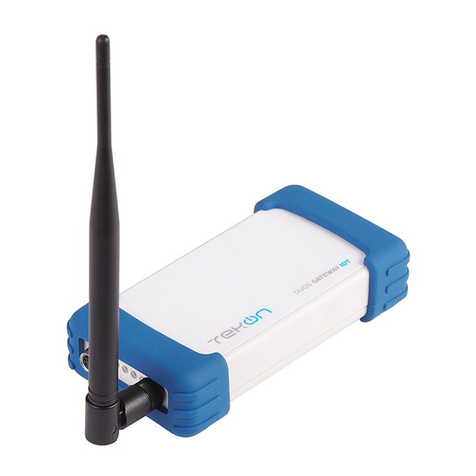
ProtoNode is an external, high performance Building Automation multi-protocol gateway that has been
preprogrammed for Harsco’s ENVI boiler control system and the Love Boiler controller to support BACnet®
1
MS/TP,
BACnet/IP, Metasys®
2
N2 by JCI, Modbus TCP, and LonWorks®
3
. Configurations for the various protocols are
stored within the ProtoNode and are selectable via DIP switches for fast and easy installation. It is not necessary to
download any configuration files to support the required applications.
This document provides the necessary information to facilitate installation of the ProtoNode.
1.1 BTL Mark –BACnet Testing Laboratory
1.2 LonMark Certification
1
BACnet is a registered trademark of ASHRAE
2
Metasys is a registered trademark of Johnson Controls Inc.
34 LonWorks is a registered trademark of Echelon Corporation
The BTL Mark on the ProtoNode RER is a symbol that indicates to everyone that a
product has passed a series of rigorous tests conducted by an independent laboratory
which verifies that the product correctly implements the BACnet features claimed in
the listing. The mark is a symbol of a high-quality BACnet product. Go to
http://www.bacnetinternational.net/btl/ for more information about the BACnet
Testing Laboratory.
LonMark International is the recognized authority for certification, education, and
promotion of interoperability standards for the benefit of manufacturers, integrators
and end users. LonMark International has developed extensive product certification
standards and tests to provide the integrator and user with confidence that products
from multiple manufacturers utilizing LonMark devices work together. FieldServer
Technologies has more LonMark Certified gateways than any other gateway
manufacturer, including the ProtoCessor, ProtoCarrier and ProtoNode for OEM
applications and the full featured, configurable gateways.

Harsco Industrial Patterson-Kelley ProtoNode Startup Guide Page 6 of 38
ProtoCessor 1991 Tarob Court Milpitas, California 95035 USA Web: www.protocessor.com
Tel: (408) 964 4444 Fax: (408) 964 4425 Toll Free: (800) 317 8319 email: support@protocessor.com
2BACNET/LONWORKS SETUP FOR PROTONODE RER/LER
2.1 Installation steps for the customer
1. Record the information about the unit. See Section 2.2
2. Configure each ENVI controller’s Modbus node address for each ENVI connected to the ProtoNode. The
first node must start at 1 and go up to 16; if you have a total of 16 ENVI’s connected to the ProtoNode.
See Appendix B.1
3. For Love Controller connected to the ProtoNode, the Modbus Node address must be set to 1. See
Appendix B.1
4. Set A, B, and S DIP Switch banks on ProtoNode for field protocol baud rate, Node-ID/Device Instance, and
proper configuration. See Section 2.3
5. Connect the ProtoNode to the Field protocol port (3 pin Phoenix connector) and the ENVI’s or Love
Controller’s RS-485 port to the ProtoNode’s RS-485 interface (located on the ProtoNode’s 6 pin
connector). See Section 3
6. Power up the ProtoNode RER and LER. See Section 3.6
7. Commission the ProtoNode on the LonWorks Network. This needs to be done by the LonWorks
administrator use a LonWorks Commissioning tool. See Section 4
8. If the Field protocol is BACnet/IP or Modbus TCP, refer to Section 4 to run the ProtoNode Web GUI to
change IP address. See Section 5
2.2 Record Identification Data
Each ProtoNode has a unique part number located on the underside of the unit. The numbers are as
follows:
Part number FPC-N34-103-126-0710:
oSupports 1 through 16 ENVI boilers to BACnet/IP, BACnet MS/TP, Modbus TCP, and
Metasys N2.
oSupports 1 Love controller to BACnet/IP, BACnet MS/TP, Modbus TCP, and Metasys N2.
Part number FPC-N35-103-401-0771:
oSupports 1 through 13 ENVI boilers to LonWorks.
oSupports 1 Love controller to LonWorks.
These part numbers should be recorded, as they may be required for technical support.
2.3 Configure the DIP Switches
2.3.1 Setting the Node/ID Device Instance (DIP Switch A0 –A7) for BACnet MS/TP,
BACnet/IP, and Metasys N2
The A Bank DIP switches on the ProtoNode RER allow users to set the Node-ID/Device Instance on the
Field RS-485.

Harsco Industrial Patterson-Kelley ProtoNode Startup Guide Page 7 of 38
ProtoCessor 1991 Tarob Court Milpitas, California 95035 USA Web: www.protocessor.com
Tel: (408) 964 4444 Fax: (408) 964 4425 Toll Free: (800) 317 8319 email: support@protocessor.com
DIP switches A0 –A7 can also be used to set the MAC Address for BACnet MS/TP and BACnet/IP
Figure 1: A0 –A7 DIP Switches
Please refer to Appendix B.3 for the full range of addresses to set Node-ID/Device Instance.
NOTE: When setting DIP Switches, please ensure that power to the board is OFF.
2.3.2 Setting the Serial Baud Rate (DIP Sw itch B0 –B3) for BACnet MS/TP and Metasys
N2 ProtoNodes
DIP Switches B0 –B3 can be used to set the serial baud rate to match the baud rate provided by the
Building Management System for BACnet MS/TP.
Metasys N2 is always defaulted to 9600 baud and the B bank is disabled.
B0 B1 B2 B3
Figure 2: B0 –B3 DIP Switches
2.3.2.1 Baud Rate DIP Switch Selection
Baud
B0
B1
B2
B3
9600
On
On
On
Off
19200
Off
Off
Off
On
38400
On
On
Off
On
57600
Off
Off
On
On
76800
On
Off
On
On
2.3.3 Using S0 –S3 bank of DIP Switches to select and load Configuration Files for ENVI
and Love Controller
The S bank of DIP switches, S0 - S3 is used to select and load a configuration file from a group of
pretested/preloaded configuration files which are stored in the ProtoNode RER FPC-N34-103-126-0710
(BACnet MS/TP, BACnet/IP, Modbus TCP, Metasys N2) and the ProtoNode LER FPC-N35-103-401-0771
(LonWorks).
S0 S1 S2 S3
Figure 3: S0 –S3 DIP Switches

Harsco Industrial Patterson-Kelley ProtoNode Startup Guide Page 8 of 38
ProtoCessor 1991 Tarob Court Milpitas, California 95035 USA Web: www.protocessor.com
Tel: (408) 964 4444 Fax: (408) 964 4425 Toll Free: (800) 317 8319 email: support@protocessor.com
2.3.3.1 S0 –S3 DIP Switch Configuration Settings
A. BACnet MS/TP and BACnet IP for ENVI boilers
The following chart describes S0 - S3 DIP Switch configuration settings for the ENVI’s 1 through 16 boilers
applications to support BACnet MS/TP and BACnet/IP on a ProtoNode RER (Part # FPC-N34-103-126-
0710).
ProtoNode RER FPC-N34-103-126-0710
ProtoNode S Bank DIP Switches
Profile
S0
S1
S2
S3
BACnet IP/BACnet MS/TP 1 ENVI
Off
Off
Off
Off
BACnet IP/BACnet MS/TP 2 ENVI
On
Off
Off
Off
BACnet IP/BACnet MS/TP 3 ENVI
Off
On
Off
Off
BACnet IP/BACnet MS/TP 4 ENVI
On
On
Off
Off
BACnet IP/BACnet MS/TP 5 ENVI
Off
Off
On
Off
BACnet IP/BACnet MS/TP 6 ENVI
On
Off
On
Off
BACnet IP/BACnet MS/TP 7 ENVI
Off
On
On
Off
BACnet IP/BACnet MS/TP 8 ENVI
On
On
On
Off
BACnet IP/BACnet MS/TP 9 ENVI
Off
Off
Off
On
BACnet IP/BACnet MS/TP 10 ENVI
On
Off
Off
On
BACnet IP/BACnet MS/TP 11 ENVI
Off
On
Off
On
BACnet IP/BACnet MS/TP 12 ENVI
On
On
Off
On
BACnet IP/BACnet MS/TP 13 ENVI
Off
Off
On
On
BACnet IP/BACnet MS/TP 14 ENVI
On
Off
On
On
BACnet IP/BACnet MS/TP 15 ENVI
Off
On
On
On
BACnet IP/BACnet MS/TP 16 ENVI
On
On
On
On
Support for 1 through 16 ENVI’s to Metasys N2 or Modbus TCP see Appendix B.2
Support for 1 Love Controller to support BACnet MS/TP, BACnet/IP, Metasys N2 or Modbus TCP
see Appendix B.2
S Bank DIP Switches

Harsco Industrial Patterson-Kelley ProtoNode Startup Guide Page 9 of 38
ProtoCessor 1991 Tarob Court Milpitas, California 95035 USA Web: www.protocessor.com
Tel: (408) 964 4444 Fax: (408) 964 4425 Toll Free: (800) 317 8319 email: support@protocessor.com
B. LonWorks for ENVI boilers
The following chart describes the DIP switch settings for the ENVI and Love controllers to support
LonWorks (Part # FPC-N35-103-401-0771).
ProtoNode LER FPC-N35-103-401-0771
ProtoNode S Bank DIP Switches
Profile
S0
S1
S2
S3
LonWorks 1 ENVI
Off
Off
Off
Off
LonWorks 2 ENVI
On
Off
Off
Off
LonWorks 3 ENVI
Off
On
Off
Off
LonWorks 4 ENVI
On
On
Off
Off
LonWorks 5 ENVI
Off
Off
On
Off
LonWorks 6 ENVI
On
Off
On
Off
LonWorks 7 ENVI
Off
On
On
Off
LonWorks 8 ENVI
On
On
On
Off
LonWorks 9 ENVI
Off
Off
Off
On
LonWorks 10 ENVI
On
Off
Off
On
LonWorks 11 ENVI
Off
On
Off
On
LonWorks 12 ENVI
On
On
Off
On
LonWorks 13 ENVI
Off
Off
On
On
LonWorks 1 Love
On
Off
On
On
ProtoNode LER will only support up to 13 ENVI’s on LonWorks. If you need more than 13 ENVI’s then you
will need to add another ProtoNode LER.
NOTE: When setting DIP Switches, please ensure that power to the board is OFF.

Harsco Industrial Patterson-Kelley ProtoNode Startup Guide Page 10 of 38
ProtoCessor 1991 Tarob Court Milpitas, California 95035 USA Web: www.protocessor.com
Tel: (408) 964 4444 Fax: (408) 964 4425 Toll Free: (800) 317 8319 email: support@protocessor.com
3INTERFACING THE PROTONODE TO ENVI AND LOVE CONTROLLER
3.1 ProtoNode RER and LER component layout with the cover removed
Figure 4: ProtoNode BACnet RER N34 (top) and ProtoNode LER N35 (bottom)

Harsco Industrial Patterson-Kelley ProtoNode Startup Guide Page 11 of 38
ProtoCessor 1991 Tarob Court Milpitas, California 95035 USA Web: www.protocessor.com
Tel: (408) 964 4444 Fax: (408) 964 4425 Toll Free: (800) 317 8319 email: support@protocessor.com
3.2 Wiring Connections to ProtoNode RER and LER for the ENVI and Love Controller
ProtoNode 6 Pin Phoenix connector –Pin outs to ENVI’s and Love’s Modbus RTU and Power
Figure 5: Pin outs for the ENVI’s Modbus RS-485 port and power to the ProtoNode
Figure 6: Pin outs for the Love’s Modbus RS-485 port and power to the ProtoNode

Harsco Industrial Patterson-Kelley ProtoNode Startup Guide Page 12 of 38
ProtoCessor 1991 Tarob Court Milpitas, California 95035 USA Web: www.protocessor.com
Tel: (408) 964 4444 Fax: (408) 964 4425 Toll Free: (800) 317 8319 email: support@protocessor.com
3.2.1 Connecting ENVI Modbus RTU Boilers to the ProtoNode’s RS -485
Connect ENVI’s Modbus COM 1A (RS485+) to ProtoNode’s pin 1 labeled B+ (RS485+) on the Phoenix 6 pin
connector.
Connect ENVI’s Modbus COM 1B (RS485-) to ProtoNode’s pin 2 labeled A- (RS485-) on the Phoenix 6 pin
connector.
Do not connect Ground between ENVI and the ProtoNode’s RS485 Ground.
Figure 7: Wiring diagram for the EVNI’s Modbus RTU RS-485 to the ProtoNode’s RS-485 port.
3.2.2 Biasing the Modbus RS-485 Network
An RS-485 network with more than one device needs to have biasing to ensure proper communication.
The biasing needs to be done on one device.
None of the ENVI’s support biasing.
The ProtoNode has a 510 Ohm resistor switch that is used to set the biasing. The ProtoNode’s default
position for the Biasing switch is ON from the factory.
The biasing MUST always be left in the ON position. The ON position is when the 2 RED biasing jumpers
straddle the 4 pins closest to the inside of the board of the ProtoNode. See Figure 8 below

Harsco Industrial Patterson-Kelley ProtoNode Startup Guide Page 13 of 38
ProtoCessor 1991 Tarob Court Milpitas, California 95035 USA Web: www.protocessor.com
Tel: (408) 964 4444 Fax: (408) 964 4425 Toll Free: (800) 317 8319 email: support@protocessor.com
Figure 8: Modbus RS-485 Biasing Switch on the ProtoNode N34 (left) and ProtoNode N35 (left).
3.2.3 End of Line Termination Switch for the Modbus RS-485 port on the ProtoNode
On long RS-485 cabling runs, the RS-485 trunk must be properly terminated at each end.
If the ProtoNode is placed at one of the ends of the trunk, you turn the Blue RS-485 End-of- Line
Terminating switch to ON position.
On short cabling runs which most of the ENVI applications are, the EOL switch does not to need to be
turned ON. The default setting for this Blue EOL switch is OFF.
All ways leave the single Red Jumper in the A position.
Figure 9: Modbus RS-485 End-Of-Line Termination Switch on the ProtoNode N34 (left) and ProtoNode N35 (right)
RS-485 Bias Switch
RS-485 Bias Switch
Modbus RS-485 EOL Switch
Switch
Modbus RS-485 EOL Switch
EOLEOL Switch
Leave in A Position

Harsco Industrial Patterson-Kelley ProtoNode Startup Guide Page 14 of 38
ProtoCessor 1991 Tarob Court Milpitas, California 95035 USA Web: www.protocessor.com
Tel: (408) 964 4444 Fax: (408) 964 4425 Toll Free: (800) 317 8319 email: support@protocessor.com
3.3 Wiring the ProtoNode RER to RS-485 Field Protocol
Connection from ProtoNode RER to BACnet MS/TP and Metasys N2 networks
Connect BACnet MS/TP or N2 RS485 to the 3-pin RS485 connector on ProtoNode RER as shown below.
Figure 10: Connection from ProtoNode to RS-485 BMS Field Protocol –BACnet MS/TP or Metasys N2
See Section 4 for information on connecting the ProtoNode RER to BACnet/IP or Modbus TCP network.
If the ProtoNode is the last device on the BACnet MS/TP or Metasys N2 RS-485 trunk, then enable the
End-of-line termination needs to be enabled. The default is off.
Figure 11: End-of-line termination on from ProtoNode to RS-485 BMS Field Protocol
End-of-Line Switch

Harsco Industrial Patterson-Kelley ProtoNode Startup Guide Page 15 of 38
ProtoCessor 1991 Tarob Court Milpitas, California 95035 USA Web: www.protocessor.com
Tel: (408) 964 4444 Fax: (408) 964 4425 Toll Free: (800) 317 8319 email: support@protocessor.com
3.4 Wiring the ProtoNode LER Field Port to a LonWorks network
Connect the ProtoNode to the field network with the LonWorks terminal using a twisted pair non-
shielded cable. LonWorks has no polarity.
Figure 12: ProtoNode LER LonWorks FFT-10 2 wire screw terminal
3.5 Power-Up the ProtoNode RER or LER
Apply power to the device. Ensure that the power supply used complies with the specifications provided in
Appendix C.1. Ensure that the cable is grounded using the “Frame-GND” terminal. The ProtoNode is factory set to
accept both 9-30VDC and 12-24 VAC.
Voltage Pin outs
Figure 13: ProtoNode power pin outs

Harsco Industrial Patterson-Kelley ProtoNode Startup Guide Page 16 of 38
ProtoCessor 1991 Tarob Court Milpitas, California 95035 USA Web: www.protocessor.com
Tel: (408) 964 4444 Fax: (408) 964 4425 Toll Free: (800) 317 8319 email: support@protocessor.com
4COMMISSIONING THE PROTONODE LER ON A LONWORKS NETWORK
Commissioning may only be performed by the LonWorks administrator.
4.1 Commissioning the ProtoNode LER on a LonWorks network
To commission the ProtoNode LER LonWorks port, insert a small screwdriver in the commissioning hole on the
face of the LER’s enclosure to access the Service Pin. See the illustration on the ProtoNode LER as to which way to
toggle the screw driver during commissioning.
If an XIF file is required, see steps Section 4.4.1 to generate XIF
4.1.1 Instructions to Upload XIF File From the ProtoNode LER Using FS GUI Web Server
Connect a standard cat5 Ethernet cable between the PC and ProtoNode
The Default IP Address of the ProtoNode is 192.168.1.24, Subnet Mask is 255.255.255.0. If the PC and the
ProtoNode are on different IP Networks, assign a static IP Address to the PC on the 192.168.1.xxx network
For Windows XP:
Go to > >
Right-click on Local Area Connection > Properties
Highlight >
For Windows 7:
Go to > >
> >
Right-click on Local Area Connection > Properties
Highlight >
LonWorks Service Pin

Harsco Industrial Patterson-Kelley ProtoNode Startup Guide Page 17 of 38
ProtoCessor 1991 Tarob Court Milpitas, California 95035 USA Web: www.protocessor.com
Tel: (408) 964 4444 Fax: (408) 964 4425 Toll Free: (800) 317 8319 email: support@protocessor.com
For Windows XP and Windows 7, select: Use the following IP address
Click twice
Open a web browser and go to the following address: IP address of ProtoCessor/fserver.xif
Example: 192.168.1.24/fserver.xif
Download and save the file onto the PC.
Figure 14: Sample of Fserver.XIF file being generated

Harsco Industrial Patterson-Kelley ProtoNode Startup Guide Page 18 of 38
ProtoCessor 1991 Tarob Court Milpitas, California 95035 USA Web: www.protocessor.com
Tel: (408) 964 4444 Fax: (408) 964 4425 Toll Free: (800) 317 8319 email: support@protocessor.com
5CONNECT THE PROTONODE’S WEB GUI TO SETUP IP ADDRESS FOR BACNET/IP OR
MODBUS TCP
5.1 Connect the PC to the ProtoNode via the Ethernet port
Figure 15: Ethernet port location of ProtoNode
Connect a standard CAT5 Ethernet cable (straight through or cross) between the PC and ProtoNode
The Default IP Address of the ProtoNode is 192.168.1.24, Subnet Mask is 255.255.255.0. If the PC and the
ProtoNode are on different IP Networks, assign a static IP Address to the PC on the 192.168.1.xxx network
Go to > >
Right-click on Local Area Connection > Properties
Highlight >
Select: Use the following IP address
Click twice
Ethernet Port

Harsco Industrial Patterson-Kelley ProtoNode Startup Guide Page 19 of 38
ProtoCessor 1991 Tarob Court Milpitas, California 95035 USA Web: www.protocessor.com
Tel: (408) 964 4444 Fax: (408) 964 4425 Toll Free: (800) 317 8319 email: support@protocessor.com
5.2 Use the ProtoNode Web GUI to Connect to the ProtoNode
Open PC web browser; enter the default IP address of the ProtoNode 192.168.1.24, to determine if the
ProtoNode is up and communicating.
Figure 16: FST Web GUI screen
5.3 Set IP Address for BACnet/IP or Modbus TCP via GUI
Open a PC web browser, enter the default IP address of the ProtoNode 192.168.1.24 and connect to the
ProtoNode.
From the GUI main home page, click on setup and then Network Settings to enter the Edit IP Address
Settings menu.
Modify the IP address (N1 IP address field) of the ProtoNode Ethernet port.
If necessary, change the Netmask (N1 Netmask field).
Type in a new Subnet Mask.
If necessary, change the IP Gateway (Default Gateway field).
Type in a new IP Gateway.
Note: If the ProtoNode is connected to a router, the IP Gateway of the ProtoNode should be set to the IP
address of the router that it is connected to.
Reset ProtoNode.
Unplug Ethernet cable from PC and connect it to the network hub or router.

Harsco Industrial Patterson-Kelley ProtoNode Startup Guide Page 20 of 38
ProtoCessor 1991 Tarob Court Milpitas, California 95035 USA Web: www.protocessor.com
Tel: (408) 964 4444 Fax: (408) 964 4425 Toll Free: (800) 317 8319 email: support@protocessor.com
Figure 17: FST Web GUI IP Address settings screen
This manual suits for next models
1
Table of contents
Other ProtoCessor Gateway manuals
