proTon pack v2 User manual

proTon pack
V2 USER MANUAL (draft 1.0)
patent pEndIng

proTon packV2
page 2
Table of Contents
1. Product Features
A. Main Proton Pack Frame (exterior)
B. Main Proton Pack Frame (interior)
C. Main Proton Pack Frame (sides)
D. Power Pigtail Cables
E. Standard Kit Contents
2. Introduction & Basic Usage
A. General Description
B. Basic Use
3. Power System
A. Power System Introduction
B. 14v Priority swap mode
C. 14v Parallel swap mode
D. 28v mode
E. LED Indicators
F. Circuit Breakers
4. Battery Plates
A. Standard Plates
B. Swapping Battery Plates
C. Using 26v Batteries
5. Peripheral Mounting
A. Using the Velcro pads
B. Proton Pack Hard Mounts
C. Using the Dovetail Spine
D. Using the Center Spine Cheeseplate
6. Proton Pack Accessories
A. Using the Strain Relief Cable
B. Using the Rain Cover
C. Attaching the Waist Belt
D. Attaching the Heavy Lift System
7. Care & Maintenance
A. Removing & Cleaning the Backpack pad
B. Accessing the Internal Electronics Case
C. Replacing Circuit Pop Breakers
D. Replacing Battery Fuses
8. Technical Information
A.ProtonPackSpecications
B. Pin-outs
C. Detailed Dimensions
...................................................................................... page 3
.............................................................................. 3
................................................................................ 4
.................................................................................. 5
..................................................................................................... 6
.................................................................................................... 7
..................................................................... page 8
...................................................................................................... 8
.......................................................................................................................... 8
............................................................................................ page 9
........................................................................................... 9
.................................................................................................. 9
............................................................................................... 9
........................................................................................................................ 9
................................................................................................................ 10
.............................................................................................................. 11
.......................................................................................... page 11
.......................................................................................................... 11
............................................................................................. 11
....................................................................................................... 12
.............................................................................. page 13
................................................................................................. 13
........................................................................................... 13
............................................................................................. 14
........................................................................ 14
....................................................................... page 15
...................................................................................... 15
.................................................................................................... 15
............................................................................................. 16
................................................................................ 16
............................................................................ page 17
............................................................... 17
................................................................... 19
................................................................................. 20
.............................................................................................. 20
............................................................................ page 22
......................................................................................... 22
.......................................................................................................................... 23
.................................................................................................. 24

proTon packV2
page 3
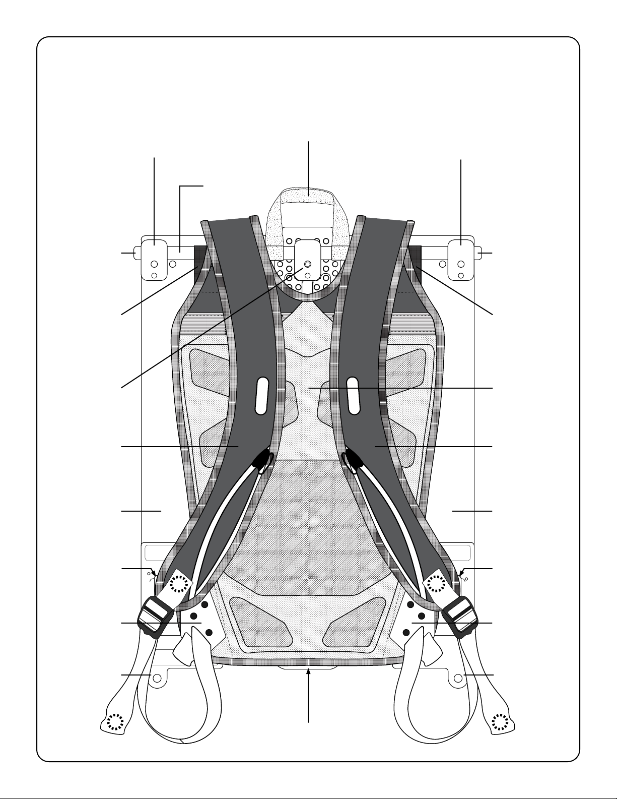
A. Main Proton Pack Frame (exterior)
carry strap webbing
6pin Lemo
main camera power port
(battery voltage)
really cool logo
3/8-16 accessory mount
w/ Arri anti-rotation holes
3/8-16 thread
w/ Arri holes
3/8-16 accessory mount
w/ Arri anti-rotation holes
velcro padvelcro pad
15mm rod
1/4-20 thread
15mm rod
1/4-20 thread
rubber
band
center spine
Arri-standard
dovetail &
cheeseplate
5/8” baby pin
1/4-20 thread
1/4-20 thread 3/8 inch
pass-through
channel
13v regulated
P-tap port
13v regulated
P-tap port
battery plate 1
(primary*)
battery 1 LED
indicator
battery 2 LED
indicator
strain relief /
3/8-16 thread
*depending on selected mode
strain relief /
3/8-16 thread
13v regulated
2pin Lemo port
13v regulated
2pin Lemo port
rubber
band
battery Plate 2
(backup*)
1. Product Features
proTon packV2
page 4
battery
1
breaker
aks power
off
-
on
breaker
battery
2
SN 00012
proTon packV2
green:
yellow:
red:
good voltage
low voltage
below cutoff/dead
blue (flash):
red (fast flash):
red (slow flash):
current overdraw
electrical fault
overheat fault
camera power :
aks power:
2pin lemos:
batt. voltage & amps
6A total [2x 2pin & 2x p-tap]
pin1 (
-
), pin2 (+)
proTon pack
proTon pack
B. Main Proton Pack Frame (interior)
carry strap webbing
carbon ber
15mm rod
center spine Arri-standard
dovetail & cheeseplate
rod mounting block
pad
attachment
strap
pad
attachment
plate
pad
attachment
plate
pad
attachment
strap
rod mounting block
15mm rod
1/4-20 thread
15mm rod
1/4-20 thread
5/8” baby Pin
release screw
shoulder strap shoulder strap
backpack pad
carbon ber
plate
waist belt
attachment
slot
waist belt
attachment
slot
carbon ber
plate
Strain Relief /
3/8-16 thread
Strain Relief /
3/8-16 thread

proTon packV2
page 5
10
10
C. Main Proton Pack Frame
(left-side) (right-side)
carry strap webbing
center spine Arri-
standard dovetail
& cheeseplate
camera circuit
breaker (10A)
accessory circuit
breaker (5A)
rod mounting block
backpack
pad
backpack
pad
pad
attachment
strap
pad
attachment
plate
pad
attachment
plate
pad
attachment
strap
rod mounting block
15mm rod
1/4-20 thread
15mm rod
1/4-20 thread
5/8” baby Pin
1/4-20 thread
shoulder strap shoulder strap
waist belt
attachment
slot
waist belt
attachment
slot
Strain Relief /
3/8-16 thread
battery plate 1
(primary*)
battery plate 2
(backup*)
*depending on selected mode
510

proTon packV2
page 6
D. Proton Pack Power Pigtail Cables
1
23
41
2
3
1
2
3
14v 4pin XLR Pigtail 14v 3pin XLR Pigtail 28v 3pin XLR Pigtail
Pin#1 (
-
), Pin#2 (+)
Pin#1 (
-
), Pin#4 (+) Pin#1 (
-
), Pin#2 (+)

proTon packV2
page 7
E. Standard Kit Complete Contents
(1x) Proton Pack Backpack Rig
(1x) Hard Shipping Case with Padded Interior and Lid Organizer
(3x) Power Pigtail Cables
(1x) Removable Waist Belt
(1x) Rain Cover
(1x) Strain Relief Cable
(2x) Preston 7pin Motor Cables (straight to right angle)
(1x) 3pin Fischer Run/Stop extension cable (female plug to male plug)
(3x) SDI BNC Cables (straight to right angle)
(1x) 5pin Lemo timecode input cable (to BNC)
(1x) Rangendersensorcable(yourchoice:Cinetape/Sniper/Lightranger)
(1x) Standard four port P-Tap splitter box
(1x) Extra long four port P-Tap splitter box
proTon packV2
page 8
2. Introduction & Basic Usage
A. General Description
ProtonPackisabackpack-worncameraaccessoriesplatform.Itprovidesmountingoptionsfor:
• Batteries (gold mount or v-mount)
• MDR
• Wireless HD Transmitter
• Timecode generator
• Cinetape readout
• Focus Monitor
Handheld shooting and cramped spaces often require cameras to be made as small as possible.
DPs often request that the camera be completely stripped-down. Proton Pack provides a solution to
accomplishthesebuildswithoutcompromisetonormalwork-ow.
Velcro surfaces and cheeseplates allow attachment for all of your professional accessories.
Camera builds can now be reduced to only body, lens, & focus motor. Proton Pack’s power system is
ready for 14v or 28v cameras and provides regulated 13v breakout power (2x p-tap & 2x Lemos) for all
peripherals.
IdealforworkingwithArriAlexaMini,RedDSMC2,andlmcameras,ProtonPackisacomplete
system providing all custom umbilical cables and accessories you will need for any build.
B. Basic Usage
• Begin by choosing the appropriate power pigtail for your camera system. For any camera that can
accept ±12v DC power the “14v” pigtails are always preferred as they maintain hot-swapability when
changing batteries. Pick the “14v” 4pin XLR or 3pin XLR pigtail based on the power cable included with
your camera*. For ±24vcamerasystems(35mmlm,AlexaLF/65,etc.)pickthe“28v”3pinXLRpigtail
• Install the power pigtail into the 6pin 2B Lemo “Camera Power” port on the Proton Pack main chassis.
• Strip down the camera body to the bare minimum of rigging (cage, baseplate, etc.). Leave only
essential accessories for shooting and operating (lens, monitor, focus motor, hand grips, etc.)
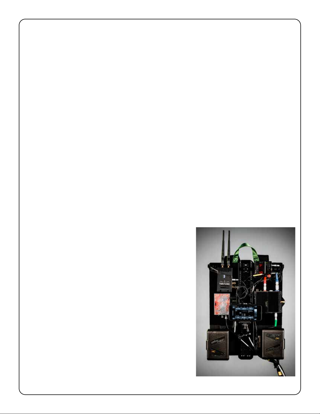
• Using Velcro or other brackets, mount all required peripherals
(Teradek/MDR/Cinetape/etc.) onto the Proton Pack frame
(Seeg.1foratypicalarrangement).
• Run power for all peripherals (using their standard power
cables) from the two 13v p-tap or two 13v 2pin Lemo ports
on the Proton Pack.
• Connect your camera power cable to the Proton Pack
Pigtail you installed earlier.
• Using the included long cables in your kit now make all
other connections between camera and Proton Pack. We
recommend starting at the camera side and taking up any
additional slack in the cables at the Proton Pack frame.
• Once the umbilical is fully assembled, we suggest attaching
the strain relief cable from umbilical to camera cage & also
securing the umbilical to the Proton Pack using the strain
relief loops at the bottom left or right corners.
• Attach batteries to both battery plates.
• Power on the camera and all accessories.
• With the Proton Pack worn by camera operator, AC or grip,
now begin shooting.
• Change batteries as needed when indicated by the yellow
“low voltage” LED.
g.1
*An 8 ft 6 in long camera power cable is ideal
proTon packV2
page 9
3. Power System & Power Modes
A. Power System Introduction
Proton Pack can provide power for both 14v and 28v camera systems from the “camera power”
port on the main chassis. This mode is automatically selected when installing either a 14v or 28v power
pigtail cable. 14v mode has hot swap. In 28v mode there is NOT full hot swap when changing batteries.
Camera power is a direct pass-through from your battery plates. Voltage and ampacity will be
reectiveofthebatteriesinuse.
The system also has four built-in ports for
powering peripherals/accessories. There are
two Anton Bauer type p-tap ports and two
standard 2pin Lemo ports. All four outputs are
regulated at 13v DC and will provide that
voltage regardless of 14v or 24v voltage mode.
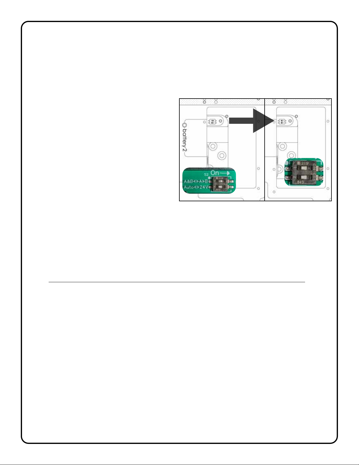
Hotswappingcanbeconguredina
“Priority”or“Parallel”protocolbyippingthe
small toggle switch located underneath “battery
plate2”(seeg.2).
g.2
B. 14v “Priority” Power Mode
This is the standard operating mode for your Proton Pack and it will ship to you with this mode pre-
selected. Choose this mode by installing one of the “14v” power pigtail cables and leaving the internal
toggle switch set to “A-->B” (right position).
In this mode your Proton Pack will always prioritize “battery plate 1” (left-hand) when there is a
healthy battery installed on that plate. “Battery plate 2” will constantly be kept in reserve as a backup if
the primary battery should die or be removed.
Only the LED on the battery plate actively supplying power will be illuminated in this mode.
C. 14v “Parallel” Power Mode
If battery plate prioritization is notdesired,yourProtonPackcanbereconguredtodrawfromboth
battery plates simultaneously. Choose this mode by installing one of the “14v” power pigtail cables and
changingtheinternaltoggleswitchto“A&B”(leftposition)(seeg.2).
In this mode the power system will actively favor whichever source has the higher voltage thus
draining both batteries in a relatively symmetrical pattern. Hot swap will function as normal whichever
battery is removed during a swap. It is recommended that batteries of approx. equal charge are used.
Both LEDs on the Proton Pack will be illuminated in this mode.
D. 28v Power Mode
Usethismodeforlmcamerasandlargercamerasystemsrequiring>24v.Choosethismodeby
installing the “28v” power pigtail (internal toggle switch has no effect in this mode). To achieve > 24v
bothbatteriesareconguredinseriessohotswapisNOTavailableinthismode.Make sure to safely
power down digital cameras before swapping batteries in 28v mode.
Both LEDs on the Proton Pack will be illuminated in this mode.
proTon packV2
page 10
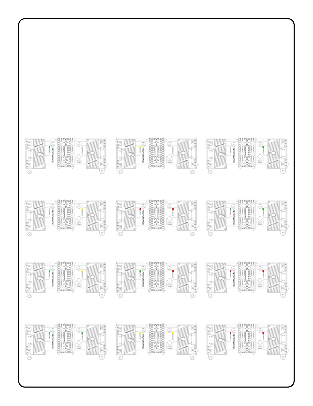
E. LED Indicators
There are two multi-color LEDs on the Proton Pack chassis, one for each battery input.
• GREEN = Good voltage ( >13v / >26v)
• YELLOW = Low voltage ( < 13v / < 26v)
• RED = Dead battery
• OFF = Battery not active or no battery present
• BLUE FLASH = Over current warning ( >10A camera, >5A accessories)
• RED FAST FLASH = Electrical system fault
• RED SLOW FLASH = System overheat ( >185 deg. F)
MODE:28v
Drawingfrom:battery1&2
Batteries:dead
28
MODE:28v
Drawingfrom:battery1&2
Batteries:low
28
MODE:28v
Drawingfrom:battery1&2
Batteries:good
28
MODE:14v,Parallel
Drawingfrom:systemoff
Batteries:bothdead
14
MODE:14v,Parallel
Drawingfrom:battery1
Batteries:1good,2dead
14
MODE:14v,Parallel
Drawingfrom:battery1&2
Batteries:1good,2low
14
MODE:14v,Parallel
Drawingfrom:battery1&2
Batteries:good
14
MODE:14v,Priority
Drawingfrom:systemoff
Batteries:bothdead
14
MODE:14v,Priority
Drawingfrom:battery2
Battery:low
14
MODE:14v,Priority
Drawingfrom:battery2
Battery:good
14
MODE:14v,Priority
Drawingfrom:battery1
Battery:low
14
MODE:14v,Priority
Drawingfrom:battery1
Battery:good
14

proTon packV2
page 11
F. Circuit Breakers
The camera output and the accessory output each have a resettable aviation-style pop breaker
which can be accessed from either side of the Pack. If there is a short circuit or other electrical fault
at the camera or on any of the accessories these circuit breakers will trip and protect the Proton Pack
from damage.
In addition, these breakers can be manually pulled so as to intentionally cut power to the camera
or on-board peripherals while leaving the batteries installed. This my be useful, for example, on a lunch
break when it is desirable to power off all accessories, but it is inconvenient to remove the batteries.
• CAMERA POP BREAKER: 10A slow-blow (Klixon 7277-2-10)
• ACCESSORY POP BREAKER: 5A slow-blow (Klixon 7277-2-5)
4. Battery Plates
A. Standard Plates
Proton Pack comes standard with the customer’s choice of pre-installed GOLD MOUNT or V-MOUNT
battery plates. These are for use with 14v-standard battery systems only.
It is possible to purchase additional plate sets from backpackrig.com and these can be changed in
theeldbytheuserifnecessary.
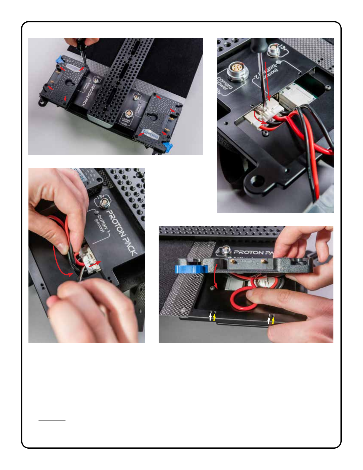
B. Swapping Battery Plates
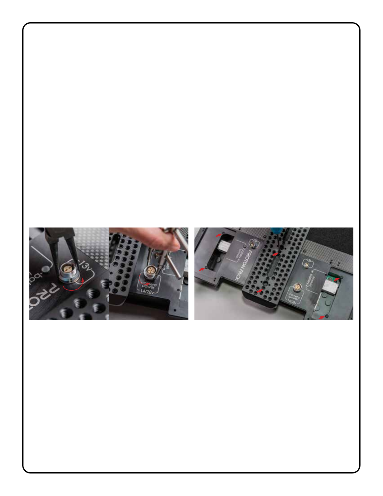
STEP1: UsingaPhillipsheadscrewdriverremovetheeightM3screwsafxingbatteryplate1and
battery plate 2 to the ProtonPackchassis(seeg.3).
STEP2: WithasmallatheadscrewdriverdepresstheupperlatchonthebeigeHiroseconnector
which attaches the battery plate to the main circuit board. Without releasing downward pressure on
the latch, use the blade of the screwdriver to wiggle the male side of the connector away from the
female header on the circuit board. Once loose from the header use the wire leads to gently pull the
connectorfreefromthecase.Repeatthisprocedureonbothbatteryplates(seeg.4).
STEP3: PerformtheoperationinSTEP2inreverse.Gentlyguidethemaleplugsofyourreplacement
batteryplatesintothecaseandslidethemintotheheadersonthecircuitboard.Ensurearmmating
andengagementoftheupperlatches(seeg.5).
STEP4: Makingsurenottopinchanywires,nowreattachthereplacementbatteryplatesusing
the provided M3 screws. IMPORTANT NOTE - Gold Mount plates utilize the lower M3 threaded holes,
V-Mount plates use the upperM3threadedholesonthechassis(seeg.6).
proTon packV2
page 12
g.3
g.4
g.6g.5
C. Use of 26v Batteries (advanced users only!)
Proton Pack is compatible with high voltage 26v-standard battery systems now available
from Anton Bauer (“Dionic 26V”) and Bebob (“Cine 12/24”). This will require swapping over to a
26v-standardbatteryplate,either:AntonBauer“GoldMountPlus,”orBebob“B-Mount.”Theseplates
will be available for purchase from backpackrig.com. Use of these batteries will allow hot-swap for 26v
cameras. This is for advanced use cases only, read all following steps before starting this conversion.
STEP1: SwapbatteryplatestoGoldMountPlusorB-Mountfollowingstepsinsection4(b).
V-Mount
Gold Mount
proTon packV2
page 13
STEP2: ***Important-Beforesecuringtheright-handbattery(plate2),changethetoggleswitch
located underneath that plate to the “24V” (right-hand) position. Finish securing both battery plates.
STEP3: Installthe yellow “14v” 3pin XLR power pigtail cable. Use only this specic pigtail cable in
this mode! Your Proton Pack will now provide 26v DC power & maintain hot swap capability during
battery changes. P-tap and 2pin Lemo ports will still deliver 13v accessory power.
***EXTREMELY IMPORTANT: DO NOT Use the red “28v” power pigtail cable when work-
ing in this mode! It will send upwards of sixty volts into the circuitry and completely
fry your Proton Pack electronics. Despite the nomenclature miss-match, only use the
yellow “14v” 3pin XLR pigtail with native 26v batteries!
5. Peripheral Mounting
A. Using the Velcro Pads
ThereisalargecarbonberplateoneithersideoftheProtonPackframecoveredinlow-prole,
industrial-strength Velcro-brand loop-side fabric. Your accessory or peripheral device can be positioned
anywhere you need on these pads by attaching a small piece of standard hook-side self-adhesive
Velcro.
We recommend placing your video transmitter high up on the pack for better signal transmission.
MDR units work best lower down, closer to the battery plates to facilitate the most direct path for focus/
irismotorcables.Timecodeand/orrangenderreadoutboxescanbepositionedwhereverthereis
roomforasensiblet.
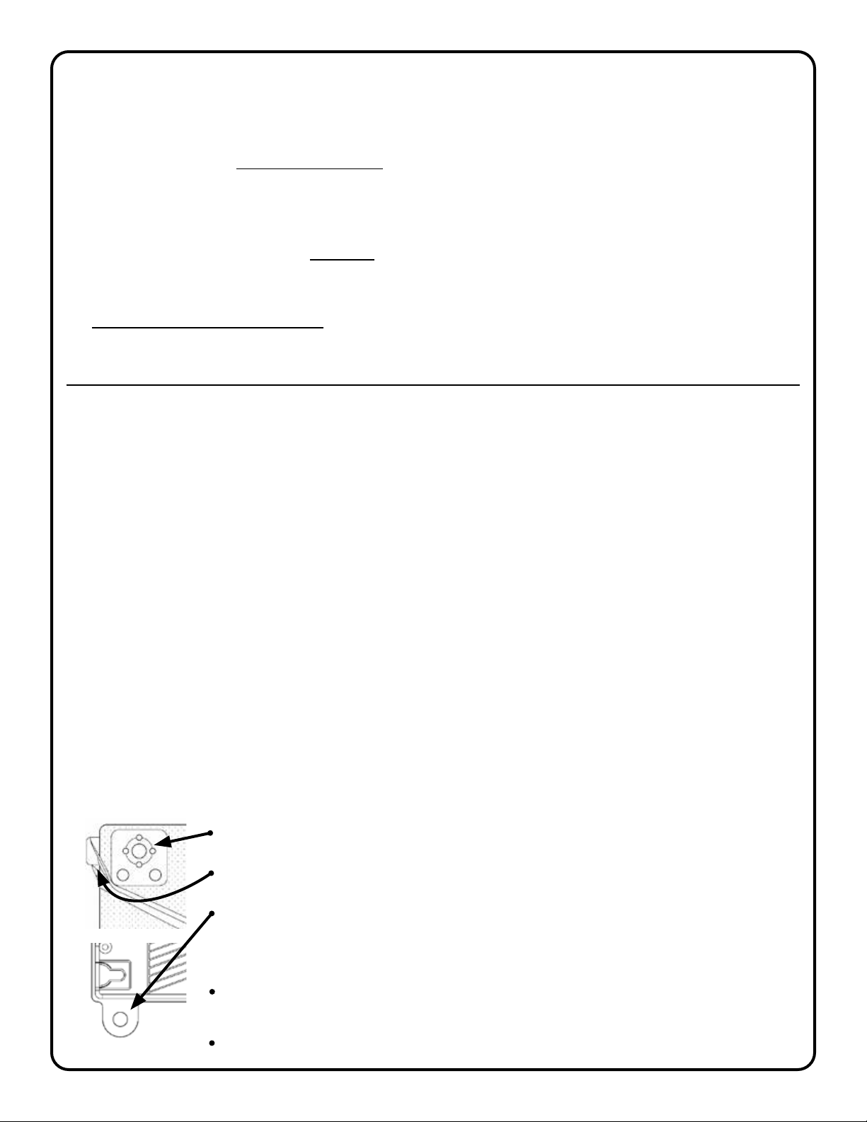
B. Proton Pack Hard Mounts
Proton Pack has a variety of built-in hard mounting points for attaching accessories which you may
prefer to bolt-on, or position with an Israeli arm or other bracket. Use these attachment points as you
would with any standard camera cage.
(2x) 3/8-16 accessory mount w/ Arri anti-rotation holes (upper left & right corners)
(2x) 1/4-20 threaded hole in 15mm rods (upper left & right corners)
(2x) 3/8-16 threaded holes on the “strain-relief” loops (lower left & right corners)
note:theseholesareespeciallyusefulforaddingbabypinstothelowerportionof
the frame when it is helpful to rig the entire backpack onto a dolly, car hood or jib.
(1x)Centerspinecheesplatewithmany,many,many1/4-20threadedholes&ve
3/8-16 Arri anti-rotation holes.
(1x) 5/8 standard baby-pin with 1/4-20 threaded hole (top of center spine)
proTon packV2
page 14
C. Using the Center Spine Dovetail
Proton Pack is equipped with an Arri-standard sliding dovetail as part of it’s center cheese-plate
spine. Camera systems like the Sony Venice Rialto and Arri Alexa-M may take advantage of this
dovetailproleformountingthecamerabodyontheoperator’sback.
STEP1: Usinga3/16imperialAllenwrench,loosenthe“5/8”babyPinreleasescrewbyapprox.1.5-
2turns.Thisislocatedontheinterioroftheframe,justabovethebackpackpad(seeg.7)
STEP2: Nowlooseenoughtounscrewbyhand,remove
the baby pin at the top of the center spine and set it aside.
STEP3: Re-tightenthe“5/8”babyPinreleasescrew.
STEP4: AttachanyArri-typebaseplate(ArriBP-8,BP-12,
etc.) to the bottom of your camera body.
STEP5: Slidingdownwardfromthetopofthebackpack,
attach the camera body to the dovetail and lock it in place. g.7
STEP6(optional): Ifdesired(andpresumingthereisenoughclearance)reattachthebabypinby
repeating steps 1 and 2.
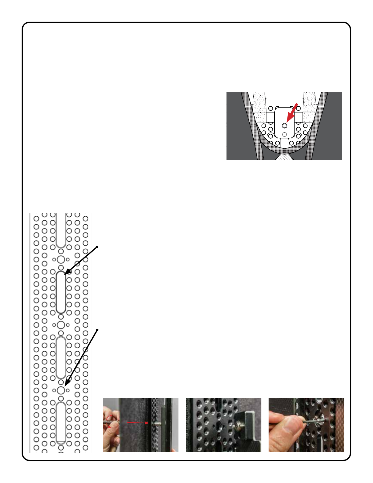
D. Using the Center Spine Cheeseplate
TheProtonPackcentralspineisequippedwithve3/8inchpass-through
channels,ve3/8-16Arripatternholesaswellasatleastseveralthousand1/4-20
threaded holes.
Pass-ThroughChannels:
By inserting a 3/8 inch bolt from the rear/interior of the cheese-plate spine it is
possible to attach a quick release or camera body directly to the surface of the
spineexactlyasyouwouldwithanynormaltripodquickreleaseplate(seeg.8).
To access the back of the spine often it will be possible to simply reach your
hand in the gap behind the backpack pad from the side of the frame. If more
room is required, detach the bottom portion of the backpack pad (see section
7(A), pg. 17) and fold it up out of your way.
3/8-16ArriAnti-RotationHolePatterns:
Attach any 3/8 inch accessory featuring Arri-standard anti-rotation pins to the
frontfaceofthespine(seeg.9).
Additionally, it is possible to insert the two included steel pins from the interior
of the plate and thread them into the rear of the M3 anti-twist holes using a 1.5mm
Allen wrench. Now female-threaded accessories with anti-rotation holes can be
hardmountedtothefaceoftheplatewithastandard3/8-16screw(seeg.10).
g.8 g.9 g.10
battery
1
breaker
aks power
off
-
on
breaker
battery
2
SN 00012
proTon packV2
green:
yellow:
red:
good voltage
low voltage
below cutoff/dead
blue (flash):
red (fast flash):
red (slow flash):
current overdraw
electrical fault
overheat fault
camera power :
aks power:
2pin lemos:
batt. voltage & amps
6A total [2x 2pin & 2x p-tap]
pin1 (
-
), pin2 (+)
proTon pack
proTon pack
proTon packV2
page 15
6. Proton Pack Accessories
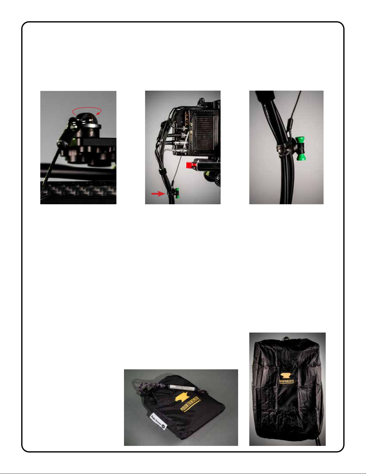
A. Using the Strain Relief Cable
Your Proton Pack ships with an included strain relief cable. It is intended to be utilized at the camera
bodytocreateaexibleconnectionbetweencameracageandthecableumbilical.Thiswillavoid
tugging and potential damage to the connectors on your camera.
g.11 g.12 g.13
STEP1: Attachthestrainreliefcabletothecamerausingthebuilt-in1/4-20threadedring.Ifpossible
pick a spot near the top of the camera adjacent to the majority of the main camera connection ports
(seeg.11).
STEP2: Pickanattachmentpointontheumbilicaljustslightlyfartherfromthecamerathantheend
of strain relief. The strain relief is 12 inches long so we recommend picking a spot about 14-16 inches
downthelengthoftheumbilical(seeg.12).
STEP3: Usethepre-attachedrubbertietowraparoundtheumbilicalatthespotselectedinstep
2.Theumbilicalshouldnowbeafxedrmlytotheendofthestrainrelief.Thereshouldbejustenough
slack above the connection point so that the weight of the umbilical is transferred directly to the
cameracage,avoidingstressontheconnectors(seeg.13).
B. Using the Rain Cover
UsetheincludedrainytoprotectyourProtonPackfromthe
elements. Simply unpack the cover from its built-in storage sack and
wrap it around the Proton Pack frame making sure all devices and
batteries are completely covered. Secure the cover in place by
pulling tight the cinch cord.

proTon packV2
page 16
C. Attaching the Waist Belt
Every Proton Pack comes with a lightweight waist belt included. Many operators choose to forgo
this option, but it is easy to attach if added support is desired for heavier builds or more acrobatic
movement.
g.14
STEP1: Retrievethewaistbeltfromthe
lid of your kit and un-loop the webbing from
the two tri-glides on either end of the belt
(seeg.14). g. 15
STEP2: Slipthefreeendofthewaistbeltwebbingthroughtheattachmentslotoneithersideofthe
frameinterior(seeg.15).
STEP3: Feedtheopenendofthewaistbeltbackthroughthetri-glideandensureasecure
connection.
D. Attaching the Heavy Lift System
The “Heavy Lift” system is a new set of accessories for Proton Pack now available at
backpackrig.com. The set includes a full-size backpacking-style waist belt and two supplementary
shoulder pads for more support and comfort when shooting with heavy Sony Venice Rialto or
Alexa-M-style camera bodies attached to the frame.
STEP1: Detachthestandardshoulderstrapwebbingsfromtheshoulderpads(seeg.16)
STEP2: Removetheeightblack1/4-20screwsfromthebaseofthebackpackpadandsetaside
thetwosmallcarbonberpadattachmentplates(seesection5(A)).Youcanleavethewebbings
attached to these plates (seeg20).
STEP3: Positiontheheavyliftwaistbeltandusetheoriginalblack1/4-20screwstoafxittothe
frame through the eight silver grommets. These will line up exactly with the pad attachment holes on
eachside(seeg17).
STEP4: Attachthehorizontal3/4in.webbingstotheirrespectivecinchesoneithersideofthewaist
beltandpullthesetight(seeg.18).
STEP5: Attachtheverticalwebbingsoneithersideoftheheavyliftwaistbelttotheshoulderstrap
cinches(seeg.16).
STEP6: Matchingthelogicalcurveofthestraps,addthesupplementarypadsoneithershoulder
strapusingtheVelcroaps(seeg.19).

proTon packV2
page 17
g.16
g.17
g.19g.18
7. Care & Maintenance
A. Removing & Cleaning the backpack pad
Periodically it may be necessary to remove the backpack pad either for cleaning or to access the
interior of the dovetail spine (for access alone, follow just STEP 1 & fold the pad up out & of the way).

proTon packV2
page 18
STEP1: Usinga5/32Allenwrench,removetheeightblack1/4-20screwsonthepadattachment
platesateithersideofthelowerportionofthebackpackpad(seeg.20).
STEP2: Removethetwoblackpadattachmentstrapsatthetopportionofthebackpackpad
whichafxittothehorizontal15mmcarbonberrod(seeg.21).
STEP3: Usinga3/16imperialAllenwrench,loosenthe“5/8”babyPinreleasescrew”byapprox.1.5
-2turns.Thisislocatedontheinterioroftheframe,justabovethebackpackpad(seeg.7)
STEP4: Nowlooseenoughtounscrewbyhand,removethebabypinatthetopofthecenterspine
and set it aside.
STEP5: Nowunscrewthe“babyPinreleasescrew”allthewaysothatthecenterrodbracketisfree
from the center spine.
STEP6: Releasethegraywebbingstrapatthetopcenterofthebackpackpadbyslidingitout
between the rod bracket and the dovetail spine. The backpack pad is now fully disconnected from
theProtonPackframe(seeg.22).
STEP7: Pullawaythecarbonberpadattachmentplatesfromthebottomofthebackpackpad
and unloop their straps from the shoulder pads. The backpack pad can now be machine washed on
coldandairdried(seeg.23).
g.20
g.22
g.21
g.23
proTon packV2
page 19
B. Accessing the Internal Electronics Case
It may be necessary to open the electronics case in the Proton Pack lower chassis in order to
replace circuit breakers, replace connectors, or to make software updates.
STEP1: Usinga5/32Allenwrench,removetheeightblack1/4-20screwsonthepadattachment
platesateithersideofthelowerportionofthebackpackpad(seeg.20).
STEP 2: UsingaPhillipsheadscrewdriverremovetheeightM3screwsafxingbatteryplate1and
battery plate 2 to the ProtonPackchassis(seeg.3).
STEP3: WithasmallatheadscrewdriverdepresstheupperlatchonthebeigeHiroseconnector
which attaches the battery plate to the main circuit board. Without releasing downward pressure on
the latch, use the blade of the screwdriver to wiggle the male side of the connector away from the
female header on the circuit board. Once loose from the header, use the wire leads to gently pull the
connectorfreefromthecase.Repeatthisprocedureonbothbatteryplates(seeg.4).
STEP4: Usingaspannerwrenchorsmallneedle-nosepliers,unscrewthechassis-mountcollarson
the two 13v 2pin Lemo ports as well as on the main camera power Lemo port. Set aside the collars and
lockwashersinasafeplace(seeg.24).
STEP5: Usinga2mmAllenwrenchremovethesixM3screwswhichafxtheelectronicscasetothe
Proton Pack chassis. Four black screws are immediately visible at the corners of the case (right under
the battery plates). Two silver screws are located in the case center beneath the dovetail spine. These
can be unscrewed by passing the Allen wrench through the corresponding 1/4-20 holes in the spine
(seeg.25).
STEP6: Theelectronicscaseisnowfreetodropawayfromthebackofthemainchassis.Encourage
the attached Lemo connectors through the chassis as you lift the Proton Pack frame away from the
case.
g.24 g.25

proTon packV2
page 20
C. Replacing Circuit Pop Breakers
With the electronics case open it is easy to replace the circuit pop breakers should those become
faulty.
STEP1: Fromtheoutsideofthecase,usingasmallcrescentwrench,unscrewthepopbreaker’s
mountingnutandsetthatasidealongwiththelockwasher(seeg.26).
STEP 2: Wigglethenowfree-oatingpop-breakerthroughthesideofthecasesothatthereisslack
intheredconnectingwiresandtheterminalscrewscanbemadeaccessible(seeg.27).
STEP3: Withasmallscrewdriverunscrewthetwoterminalconnections.Becarefultokeeptrackof
thesmall6-32screwsandlockwashers.(seeg.28).
STEP4: ReplacetheoldcircuitbreakerwitheitherKLIXON 7277-2-10 (for camera output) or KLIXON
7277-2-5 (for accessories output).
STEP5: Replacethetworedwireleads,securingthemwiththeterminalsscrews,andfeedthe
breaker back out through the side of the case.
STEP6: Replaceandtightenthebreaker’souterlockwasherandmountingnutasinSTEP1.
D. Replacing Battery Plate Fuses
Each Proton Pack battery plate is equipped with a 15A slow-blow mini ATM blade fuse. Should one
ofthesebeblownorbecomefaultyitiseasilyreplacedintheeld.
STEP1: Detachthebatteryplatewiththeblownfusefromthechassis.UseaPhillipshead
screwdrivertoremovetheeightM3screwsafxingthebatteryplateandsetthemaside(seeg.3).
g.26 g.27 g.28
Table of contents
Popular Camera Accessories manuals by other brands


Basler
Basler aviator avA1000-120km user manual

Vinten
Vinten Vision 30 Maintenance manual

Anker
Anker Astro M2 Welcome guide

Clinton Electronics
Clinton Electronics CE-H13 installation guide

CamRanger
CamRanger PT Hub quick start guide

Fullriver Battery
Fullriver Battery DC Series Installation and operation manual


