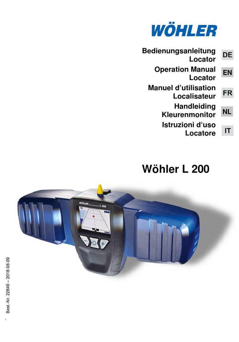
Prototek LineFinder LF2000 User manual

DIGITAL UNDERGROUND LOCATING
BREAKING NEW GROUND UNDERGROUND
HOW TO GET THE MOST OUT OF YOUR
DIGITAL LOCATING TOOLS FROM PROTOTEK
0416a
LF2000 LF2200
Training Videos for using
Prototek LineFinders
are available on our web site
www.prototek.net/video-training
Scan this with your
Smart Phone
for help in the eld

or contact us:
(800) 541-9123
Fax (360) 779-1510
Corporation
P. O. Box 1700
19044-B Jensen Way NE
Poulsbo, WA 98370
If you cant find the answer in this
manual, go to our web site:
www.prototek.net
31
Your Notes

Getting to Know your Tools............. 3
Sonde Locating .....................................5
Line Tracing.........................................11
Power Mode .......................................14
“Sniffing” Custom Frequencies ............17
At the Jobsite................................ 18
Sonde Locating ...................................19
Line and Power Tracing.......................23
Troubleshooting ............................ 26
Welcome to
Underground Locating..................... 1
Product Specifications.................... 27
“What page is the Sudoku puzzle on?”
30
• All LineFinders are designed to shut off after four minutes of inactivity
in order to save batteries. The timer is reset whenever you click
the button in any direction. This effect can be annoying if you are
concentrating on a precise locate on the Sonde screen, for example,
and it shuts off in the middle because you haven’t been pushing the
button to change the sensitivity or go to another screen. It is a good
practice to raise the sensitivity one click higher now and then during
this process to keep your LineFinder “alive.”
• On all LineFinders (LF2000, LF2100 and LF2200) the clicking gets faster
as the signal gets stronger (nearer to the source). As you approach a
null point, the clicking slows down to a near stop. On the LF2200 only,
the clicking gets faster in line tracing mode when you are directly above
the line (which is technically a null). This was done because we felt it
was a more intuitive response when tracing lines.
• Only newer LF2200s include the Menu option of setting the Power
frequency. Earlier models (and the LF2100) required Prototek to set
the frequency. This user feature can be added to an existing LF2200
for those who need it.
• Newer LF2200s add an alternative Units setting “In” which will express
Depth in inches only up to 15 feet (feet only beyond that). This setting
is not otherwise documented here because its use is rare. This user
feature can be added to an existing LF2200 for those who need it.
• Older LF2000s and all LF2100s use a db (decibel) scale for expressing
sensitivity, rather than “NEAR..FAR”. 0 db is the least sensitive
(equivalent to “NEAR”), ranging up to 90 db as most sensitive
(equivalent to “FAR”), in 5 db increments. Otherwise, the operation of
all units in this regard is the same.
• The LF2100 (discontinued but still supported) offers sonde locating
for only 16 Hz and 512 kHz, without the Snifng feature. Line tracing
frequencies are the same as the LF2200, as are all other locating
procedures. The LF2100 is not upgradeable.
Operational Notes ........................ 30
Operational Notes

We have designed our equipment to be durable and reliable, and all
products are warranted for a period of one year (from date of shipment)
to be free from manufacturing defects. We will repair or replace, at our
discretion, any product covered under this warranty. All repairs are to
be performed by our technicians at our facility; any repairs attempted
by other parties risk loss of warranty protection and/or increased repair
costs.
We make every effort to ensure the quality of our products, but we
can’t control how they are used nor the conditions they are used under.
We feel condent that you will be successful in using them, but we
can’t control ground conditions, pipe conditions, your interpretation
of instructions or any of dozens of other factors beyond our control.
Therefore, we cannot be liable for any damage or loss incurred while
using this equipment due to, but not limited to, false indications,
equipment failure or misinterpretation of results.
Once inside a pipe, we cannot control the use of transmitters on the job
site, and will not warrant damage caused by conditions inside a pipe or
other work area.
During any use of this equipment, priority must be given to following
national and local safety requirements. The equipment is not approved
for use in areas where hazardous gases may be present.
Having said all that, Prototek remains dedicated to your success in
using our tools. We are always available by telephone during business
hours (7:30 AM to 5:00 PM Pacic Time, M-F) to help you understand
locating techniques and solve on-site problems. E-mail works, too, and
be sure to check our web site under “How Locating Works”. We are
constantly innovating, and we welcome your ideas.
We Guarantee Common Sense
“We have fun doing what we do
so you can too!”
The LF2200 adds line tracing capabilities to the already powerful
features of the LF2000. Locates any frequency sonde or line
exciter between 16 Hz and 100 kHz using our exclusive “snifng”
feature. Built-in support of 16 Hz (steel or ductile iron), 512 Hz
(cast iron or nonmetallic) and 8 kHz (nonmetallic only) sondes.
Traces underground metallic lines at four built-in industry standard
frequencies using external line exciter. Passively locates
underground power at 50/60 Hz. Clear LCD screens (with
automatic backlight compensation) guide you through the
steps critical to locating both sondes and lines with accurate
position as well as precise depth. Locating
is enhanced by handle vibration and LED
feedback at key locating points, in addition
to on-screen imagery. User selectable
scaling in English or Metric units.
Frequency .......Sondes at 16 Hz, 512 Hz & 8 kHz
Line tracing at 8, 16, 32 & 64 kHz
4 Custom “sniffable” settings
Passive power tracing at 50/60 Hz
Output ..............LCD Screen: Menu, Peak locate,
Crossing, Sonde, Track, Power, Depth
Automatic depth detection ....... to 25 feet (7.6M)
Controls ...........................4-way thumb switch:
Power, Gain, Screen select, Snifng
Speaker output ........ Variable rate click, mutable
Power source .............................. 6 AA Alkaline
Battery life .................................30-40 hours*
Operating temperature ............... -20 to +130˚F
(-29 to +54˚C)
Weight ..................................... 6 lbs. (2.7 Kg)
Size ......................................32” x 8” x 4-1/4”
LineFinder LF2200
Specications
29
* Battery life reduced with extensive backlight use

You have purchased some of the nest locating tools in the business,
but they don’t do magic. Your skill at handling these tools and
recognition of their strengths and weaknesses is what makes a locating
job successful. Before taking them out on their rst job, make sure
you understand how the system works.
What’s so special about “digital” tools?
Digital technology combines modern radio circuitry with
microprocessor control, allowing great versatility in the operation of
an instrument. What this means to you is tools that make judgments
from many sources of information and interact with you as the
operator to help lead you to fast, easy and accurate locating.
The following pages will take you through all the steps necessary to
understand and use your equipment. We strongly recommend that
you pay close attention to the section “Getting to Know your Tools”,
and come back to it whenever you are confused about the responses
you are seeing on actual locating jobs.
This advice applies whether you’re a rookie at underground locating or
an “old pro”. Prototek tools are extremely simple to use, and it’s easy
to outsmart yourself if you’re used to more complicated equipment and
procedures.
Welcome to Underground Locating
We are available to help!
Don’t hesitate to call us at 800-541-9123 if you get stuck.
www.prototek.net
protote[email protected]
1
Please note: These instructions should be considered
guidelines, not gospel. Every locating job presents unique
challenges, and although most will yield to “textbook”
procedures as described here, many will require a creative
approach. We strongly advise that you familiarize yourself
with the fundamentals of digital locating as described in
the section “Getting to Know Your Tools”. Armed with this
knowledge, you will be able to reason your way through most
locating challenges.
The LF2000 is a powerful and
durable receiver that is also
remarkably easy to use. Locates any
512 Hz sonde in cast iron or non-
metallic lines. Uses 6 off-the-shelf
AA alkaline batteries. A clear clicking
sound provides intuitive feedback on
signal strength – the faster the click,
the stronger the signal. Clear LCD
screens (with automatic backlight
compensation) guide you through
the steps critical to locating with
accurate position as well as precise
depth. Handle vibration at key
locating points enables fast, safe
“heads-up” locating.
LineFinder LF2000
Specications
28
* Battery life reduced with extensive backlight use
Frequency .........................................512 Hz
Output ...................................... LCD Screen:
Peak locate, Crossing,
Sonde, Depth
Automatic Depth detection ....to 25 feet (7.6 M)
Controls ........................ 4-way thumb switch:
Power, Gain, Screen select
Speaker output ................... Variable rate click
Power source ............................ 6 AA Alkaline
Battery life ...............................30-40 hours*
Operating temperature ............. -20 to +130˚F
(-29 to +54˚C)
Weight ................................... 6 lbs. (2.7 Kg)
Size ....................................32” x 8” x 4-1/4”

Know your Digital Receiver
the LF2000 and LF2200
THUMB SWITCH
The comfortable rocker switch can be
used by right-handers or lefties, with
or without gloves. Press to the right or
left to change screens; up and down
changes the gain (sensitivity).
LCD SCREEN
With each left or right click of the switch, the
screen will show, in sequence, the steps you
will need to complete the locate, whether
you’re using a sonde or a BuzzBox.
The HANDLE vibrates at key
points of the locating process.
“Heads up” locating is
faster and safer.
The PHONE
JACK accepts
standard stereo
headphones
(1/8” plug)
available from
Prototek.
The BATTERY COMPARTMENTS hold a
total of 6 “AA” alkaline cells, which will last
30-40 hours depending on the amount of
LCD screen backlight usage.
The RED LED
in the lower right
corner of the screen
lights up each time you
hit a null.
The automatic BACK LIGHT
SENSOR (lower left) illuminates
the screen when the surrounding
light is too low.
The SPEAKER is right under the
handle. We’ve improved the audio
by using a clicking sound, which
is more pleasant than the “squeal”
of other locating tools. Like a
Geiger counter, the faster the clicks,
the closer the signal. The digital
filters do a superior job of keeping
the background interference to a
minimum.
2
Product Specifications
The BuzzBox Line Exciter is the companion
to the LF2200 or any other line tracing
receiver that operates at a compatible
frequency. Enclosed in a tough, durable,
weatherproof case. Supplied with a set
of 6 foot cables with clamps and a 9 inch
stainless steel ground rod. Operates in
either Conductive or Inductive mode.
“Tracks” on the front panel indicate
proper orientation for Inductive
setup. Operates at four
industry standard frequencies,
using six standard alkaline “C”
cells.
Operating Modes ...................................................Conductive and Inductive
Frequencies ............................................. 8 kHz, 16 kHz, 32 kHz and 64 kHz
Power ........................................ 4 watts maximum, uses 6 “C” alkaline cells,
battery life approx. 10 hours continuous
Control ..................Rotary switch: “Off”, battery check, 4 frequency selections
Indicators ...........................8 LEDs indicating ground quality and battery level
Included accessories .....................Ground rod, cable set with 1/4” phone plug
Operating temperature .......................................................-20˚ to +130˚ F
(-29˚ to +54˚ C)
Weight ............................................................................. 4.8 lbs. (2.2 Kg)
Size ......................................................................9-1/2” x 7-1/2” x 4-3/8”
Specications
27
The LCD screen’s backlight will come on when the surrounding light is low. If you want to
keep it on all the time, place your finger over the sensor (lower left of screen border) or put
a piece of electrical tape over it. This will, however, drastically shorten the expected battery
life. If you choose to tape over the sensor, make sure you turn the unit off when not in use.

Getting to Know your Tools
The LF2000 and LF2200 receivers both help you locate sondes (transmitters)
the same way, using a series of screens that guide you through the steps
necessary for an accurate locate. The LF2200 additionally does line tracing,
where buried lines are energized by an external line exciter. Line tracing will be
covered later in this document.
The best place to practice is above ground where you can see how
the receiver responds to the location and position of the transmitter
or line. You may be surprised at what you see. Better to be
surprised when you have plenty of time to learn and nothing is at
stake!
Do your practicing in a place where you have plenty of room to move around;
inside in a large room, or outside on the ground.
Turn on the receiver by clicking the rocker switch
in any direction and hold it there for a second. The
friendly Prototek logo screen greets you, with our
phone number, which you should not hesitate to
call if you’re having problems. The unit performs
a brief self-test, checking circuit boards and signal
processing. If you have problems, this information
can be valuable to Prototek for troubleshooting.
Notice the arrows - the one pointing down shows
where to push to turn the unit OFF, the one pointing
right indicates that a push on the right side of the
switch will take you to the next screen. You must return to this screen
to turn the unit off
3
26
Troubleshooting
Two things to always check before you start a locate, and again
if you have trouble:
* Make sure the batteries in both your transmitter and receiver are fresh. If
in doubt, throw them out! A weak transmitter battery reduces its range,
while weak batteries in a receiver can make it act brain-damaged, as well as
reducing the range.
* Always test your transmitter and receiver above ground, for operation and
range, before sending the transmitter down the line. Every time.
The transmitter isn’t where my receiver said it was; it’s several feet off
to one side.
The most common source of errors in precise sonde locating is failure to
follow all of the locating steps in the operating instructions. It’s easy to
think when you nd a peak signal that your job is done. The LF Series
receivers will show you a sonde image on the Sonde screen at many
different places, but only one of them is the actual location of the sonde.
Pay particular attention to the Crossing screen on the LF receiver, where you
walk in a circle around the peak signal to locate the crossing nulls and from
there mark a line through the sonde. If you haven’t established that line,
you can’t accurately determine the location of the sonde or its depth.
The signal from my transmitter suddenly quit. I was following it ne,
then it disappeared.
Aside from checking batteries, determine whether it is possible that the
pipe material changed at some point, or you reached a steel tank. 512 Hz
equipment will penetrate cast iron, but not steel, ductile iron or other metal.
(Using a 16 Hz sonde with the LF2200 will overcome this problem.)
A sudden loss of signal may also mean you have encountered a null, which
is a normal part of locating. If the signal drop-off is at a particular spot, and
the signal returns when you move a little ways away, then it is a null.
Check our web site for updated troubleshooting information!
www.prototek.net/Service-Tshoot.html
and don’t hesitate to call us with questions:
800-541-9123
“It’s best to shoot trouble before it shoots you.”
This next part only applies to the LF2200
The LF2000 doesn’t have a menu because it only does one thing, so this next
part doesn’t apply to it. LF2000 users please skip to “Sonde Locating.”
The menu shows you all of the choices you have for
locating with the LF2200. The screen you see won’t
show all of these choices at the same time; it can
only display 10 lines at a time. One of the menu
choices will be highlighted (black bar), in this case
the choice for locating a 512 Hz sonde. Pushing the
thumb switch forward and back (up and down arrow
directions) scrolls the highlight through each menu
choice. The menu itself will scroll to reveal choices
that are off the screen.
Pushing the button in the direction of the right arrow
activates that choice, taking you to the next screen
in most cases. A full description of each menu
choice is on the next page.

425
When tracing a long line, the strength of the signal will diminish as you move
further from the exciter, until it is no longer strong enough to complete the
trace. This can be overcome by “leapfrogging”. Select a point on the line that
still has a clear signal and the direction of the line is well dened. Move back up
the line (toward where you started) about 20 feet. Place the BuzzBox over this
spot, with the “tracks” set parallel to the direction of the line, and use Inductive
mode (regardless of the mode you originally used to get this far). Now continue
the trace further along the line; you should nd good signal for a good distance.
If you run out of signal again, do another “leapfrog”.
Power Line Tracing Considerations
You should plan to use the Power mode on the receiver only for initial survey
of an area to detect the presence of underground power lines. Remember that
this mode is only effective if there is considerable power being drawn through
the underground lines; the signal from a light residential load probably can’t be
detected this way. Basically, if you detect a signal using Power mode you can
be fairly condent there is underground power nearby, but the lack of signal is
no guarantee that underground power does not exist in the area.
See the section titled “Power Mode” under Getting to Know your Tools for
details on using Peak Power and Null Power screens for detecting and tracing
underground power using passive techniques.
The best method to use for precise power line tracing is the Inductive mode,
using the BuzzBox, as described earlier. Usually the higher frequencies (32
kHz and 64 kHz) work best for this. If you have indications from Power mode
that there is underground power in the area, but can’t nd a conduit riser on
a building or pole nearby to initiate an Inductive locate from, you may have
success by using the following method: Determine as best you can the route
of the underground power, set the BuzzBox to 32 kHz or 64 kHz and lay it on
the ground so that the Tracks are parallel to this route, then use the LF2200 at
the same frequency to trace the induced signal. If you can trace a clear and
repeatable path this way (further than 15 feet from the BuzzBox), you can be
reasonably sure you have located and traced an underground line. Whether
this is a power line or some other underground metallic line is not certain,
unless you can trace it to an identiable source of power like a conduit riser.
Remember these things about using Power mode:
• The highest reading when using Peak Power screen will occur when the
LF2200 is at right angles to the direction of the line, directly above it.
• When using the Null Power screen, the handle vibration and solid track lines
also occur when the LF2200 is in line with the direction of the line. (Note that
this is not the way the LF2100 works on this screen.)
• Automatic depth readings is not available in Power mode.
• The presence of signal in Power mode is very dependent on the power
being drawn through the buried line. Be prepared for the signal to suddenly
disappear if the load on the line is decreased.
• Test for eld distortion by lifting the LF2200 when you have located the line
using the Null Power screen. If the apparent location moves to the right or
left as you raise it, the eld is distorted and you should use the Peak Power
screen to establish the correct location of the line.
The LF2200 Menu
Top to bottom, this is what each choice in the LF2200 menu offers you:
These are preset sonde frequencies that the
LF2200 will locate. The frequency you select here
must match the frequency of the sonde you are
going to use.
These are preset line tracing frequencies, for use
in conjunction with a line exciter like the Prototek
Blue BuzzBox. The frequency you select here must
match the frequency that is set on your line exciter.
This is the selection for passively detecting the
presence of underground power. This can be set to
50 or 60 Hz using the Power menu item (below) to
match the frequency of power in your area.
The LF2200 will “sniff” the frequency of any
operating sonde, from 16 Hz to 100 kHz. Two
custom frequencies can be set and saved.
The LF2200 will also “sniff” the frequency of any
operating line exciter between 16 Hz and 100 kHz,
and save two custom frequencies. Details on how
to use snifng are on page 17.
The bottom three menu items are “toggles”, which means you can switch
between two options by clicking the button to the right. Doing this only
changes the item you are on, and leaves you in the menu.
When you select “audio” and click to the right, the
speaker is turned off or on, toggling to the opposite
of how it was set before. The upper picture here
represents speaker “on”, the lower is “off”.
Toggle between displaying depth in Feet/inches or
Meters/decimeters by pushing the button to the
right.
Set this to match the frequency of power in your
locality, so that the LF2200 can pick it up in Power
mode. Whatever this is set to will be reected in
the Power menu item (above).
The last two items generally only need to be set once, to match your local
conditions, and never touched again. In most cases, it will have been set to
your locality already by Prototek.
The audio setting can be modied at will whenever you desire. This setting
was provided for those who nd the clicking sound during a locate distracting,
or disruptive to others in the area. The speaker is also turned off any time
you have headphones plugged in; in that case only the operator who is using
the headphones will hear the clicking (if audio is “on”).

5
24
Setting Up for Line Tracing
You will need to have access to one end of the line you want to trace, so that
you can excite it with your BuzzBox. For Conductive mode you must be able to
make a direct metallic connection to the line, or a tracer that accompanies it.
For Inductive locating, you only need to be able to get near the line where it is
out of the ground. In many cases, a line can be inductively excited even when it
is fully buried, if you know where it runs at that point.
Note: The metallic part of the line you wish to trace must be continuous -
insulating couplers or gaps in the line will end the signal at that point. This
applies to both Inductive and Conductive tracing.
For a Conductive locate, plug the cable connector into the BuzzBox and
connect the Red clamp to the line or tracer wire. Connect the Black clamp to
a good ground connection. This can be the ground rod that is supplied with
the BuzzBox, or a cold water pipe or electrical service ground rod. If you are
using the ground rod supplied with the BuzzBox, push it into the ground as far
from the excited line as possible (the cables will allow 12 feet of separation)
and at right angles to the excited line (that is, not off the end). The blue
Ground Quality LEDs should have at least 4 lit to indicate an adequate ground
connection. Wet the area around the ground rod or move it to another spot if
necessary to improve the ground quality.
For Inductive mode, the aim is to place the BuzzBox as close as possible to
the line you wish to induce signal into. It doesn’t matter if the line is in metallic
or nonmetallic conduit at this point; the signal will be induced into the wire
inside the conduit. The other requirement is that the “tracks” on the BuzzBox
label be parallel to the run of the line at that point.
When using the Inductive mode, avoid attempting to trace the line within
15 feet of the BuzzBox. The signal in this proximity to the Box can be very
misleading, even absent, due to competition between the signal the Box is
radiating into the air and the signal you are picking up from the line. This
should not be as much of a problem in Conductive mode, as the BuzzBox itself
does not radiate a signal in this mode.
How to set the BuzzBox for Inductive mode on a power line riser.
The signal will follow the line when it turns to run horizontally underground
Step 1: The Peak Screen
Go ahead and push the switch to the right to get to the Peak Screen. You may
hear some noise but the digital display should read under 10, and possibly say
“signal too weak”. Let’s look at the features on this screen that are typical of all
the locating screens.
• Battery symbol - shows battery strength,
with all black meaning full. When the black
level of the battery symbol gets near the
bottom, it’s time to replace them.
• “FAR”...”NEAR” with up and down arrows
shows you the current sensitivity setting;
FAR being the most sensitive and NEAR
the least, with two intermediate settings.
This setting can be manually controlled by
pushing the switch away from you or toward
you, as the arrows show.
• The sliding scale on the right side of the
screen shows the current signal level, at the
current sensitivity setting. It will never be
higher than “99”; whenever it reaches this
level, automatic circuitry will lower the sensi-
tivity to the next setting.
The “30” in the middle in this ex-
ample duplicates what is currently
shown on the sliding scale, and is
only seen on the Peak Screen.
Note that the receiver circuitry will automatically lower the
sensitivity when the signal gets too strong, but it will not raise
it when the signal gets weak. You would never be able to nd
your way if it did that! If you get too far away from the signal,
raise the sensitivity with the rocker switch and start over.
If you are using an LF2000, use a 512 Hz transmitter (sonde). If you have an
LF2200, use a sonde that matches a frequency you can set on the Menu. Turn
it on, toss it on the ground and walk away from it further than its range.
Turn the sensitivity up to FAR, and walk around
with the receiver held so that it hangs straight
down. Turn to the left and right in a “sweeping”
motion as you walk, keeping the receiver directly
in front of you. You will hear the receiver click at a faster rate as
you get closer to the transmitter, which will be accompanied by a
higher number in the display. When the signal gets too strong for
the current sensitivity setting, it will automatically be lowered. The
clicking will slow down at this point, but will speed up again as you
continue to approach the transmitter. You already know where the
transmitter is, but try to approach this exercise as though you didn’t.
Sonde Locating
1
23

623
Line and Power Tracing
1. Which Mode?
The rst decision you must make when starting a line tracing job is whether to
use Inductive or Conductive mode. Generally, the conditions you are working
under will dictate. Here are some considerations.
Conductive mode is always preferred if you have the choice, but you must
be able to make a direct, metallic connection to the line you wish to trace. This
mode is typically used for underground metallic pipes, metallic cables pushed
into pipes, tracer wires accompanying nonmetallic gas lines, etc.
• The signal will be stronger and will travel further than Inductive mode.
• There is less tendency for the signal you have injected into the line you are
tracing to “bleed into” adjacent lines.
Do not use Conductive mode for energized power or telephone lines!
Inductive mode is used when you can’t connect directly to the end of the line
you wish to trace. This mode is typically used for power and telephone lines,
and other metallic lines that you cannot gain direct access to.
• Maximum depth of an Inductive trace is about 6 feet.
2. Which Frequency?
The Blue BuzzBox and the LF2200 both can operate at any of 4 industry
standard frequencies: 8 kHz, 16 kHz, 32 kHz and 64 kHz. The latter
two frequencies are sometimes called “33 kHz” and “65 kHz” by other
manufacturers, but they are the same frequencies. If you are using one of
these Prototek tools with another manufacturer’s equipment, the frequency
choice will be dictated by which frequencies they have in common, but since
the LF2200 can “sniff” just about any line exciter frequency, your choices are
very broad when using it. When you have choices, the best frequency to use
will be determined by your tracing conditions. Feel free to change frequencies
as you work to nd the one that gives you the best results (making sure that
whichever you choose is set on both the BuzzBox and LF2200).
In general, lower frequencies will travel further and have less tendency to
“bleed” into adjacent underground lines. Inductive locating usually responds
best to the higher frequencies. However, remain open to trying different
frequencies to see what works best in the locating conditions you encounter.
Application note: If you have access to a pipe for inserting a cable, your
best locating method is to use a sonde on the end of the cable and locate
using the sonde procedures. If nding the exact end point of a line is
important, you can put a sonde on the end as well as using the Conductive
procedures, allowing you to trace the line and pinpoint the end of the cable.
Recognizing “Nulls”
Depending on the orientation of the transmitter with respect to the receiver,
you may encounter “dead spots” where the signal suddenly drops off. These
are called “nulls”, and rather than being an annoyance they actually provide the
means for very precise locating. These nulls happen at very specic spots, and
it’s good to recognize these. So let’s nd a few nulls.
Hold the receiver directly above the transmitter,
parallel to the long axis of the transmitter. The clicking
is fast and the Peak screen indicates a strong signal.
This is a peak signal.
Now turn the receiver to be perpendicular to the transmitter.
The click slows way down and the Peak screen indicates
almost no signal at all. This is a null. Move the receiver
around a little to see how sharp and precise this null point is,
and how dependent it is on being exactly perpendicular.
Now let’s look at some other places to nd nulls. Back away from the
transmitter and walk past it off the end, like this:
There was a small but noticeable signal drop-off just as you crossed the axis of
the transmitter. Our digital receivers have circuitry that compensates for nulls
in Peak mode, so the effect is not as sharp as it was in the previous exercise.
(You’ll see it demonstrated more dramatically in the next step.) This is called a
“crossing null” and it is a very good thing to know about. Walk around and see
that the crossing null is detected any time you cross either end of the transmit-
ter, no matter how far away you are as long as you are within range.
We’ve done all this in the Peak screen to show you where nulls are, but the
Digital receivers will do the job of guring out nulls and what they mean for
you, depending on which locating step, or screen, you are on. Step away from
the transmitter several feet and then push the switch to the right to go to the
Crossing screen.
When you have reached the point where any direction you move causes the
signal to drop off, mark that spot. Move to another place and seek this peak
signal again and see if you come back to the same spot. You should nd
yourself right over the transmitter each time. If you don’t, keep practicing until
you get consistent results.

7
22
Determining Depth the Old Fashioned Way
The front and back nulls you found earlier (using the Sonde screen) are your
landmarks for determining depth manually. Revisit them by switching to the
Sonde screen and walking about 20 feet away from the Peak Spot along the
Crossing Null line you determined using the Crossing screen. Turn the sensitiv-
ity as high as it will go. Walk the Crossing Null line toward the Peak Spot, with
the bottom of the receiver about an inch off the ground, while listening and
watching carefully. Watch for the Front or Back Null image on the screen at the
same time the clicking slows down and the red LED comes on.
The rst one you reach is the Front Null, and you should mark it clearly. Con-
tinue on this line toward the Peak Spot, where you should again encounter
reduced clicking, a red LED, a vibrating handle and the Sonde image on the
screen. Continue walking in the same direction until you reach the Back Null
and mark it as well. Measure the distance between the Front Null and Back Null
and multiply by 0.7. This is the depth of the transmitter, right below the Sonde
location.
For example, if you measured 60 inches between the Front and Back Nulls,
then the depth is 60 x 0.7 = 42 inches. Or, if you want to gure it in feet,
multiply 5 x 0.7 and you get 3.5 feet, which is again 42 inches.
The best accuracy for depth determination will be found when the transmitter
is no deeper than half of its maximum rated range. For example, use an FV-10
down to 5 or 6 feet in cast iron, 8 to 10 feet in non-metallic. That doesn’t mean
you can’t use these transmitters down to their maximum rated depth, it just
means that the digital receiver’s automatic depth reading becomes less reliable
at these depths.
And now for the depth disclaimers
All is not lost! Manual depth determination can often be accomplished in
situations where automatic depth is unreliable, and it’s always a good idea to
conrm automatic depth using this method anyway.
X
X
Warning: Even manual depth determination has its limits. If your transmitter
is deeper than 80% of its rated depth, the signal will drop off before you will be
able to detect the front and back nulls. In this case at least you know that the
transmitter is at or below this depth.
Step 2: The Crossing Screen (do not skip this step!)
This screen represents the most overlooked step for
locating with our Digital receivers. Many people gure
that the Peak screen got them to the transmitter and
they move straight to the Sonde screen to get the black
sonde icon. And then they complain that the transmitter
is not where it said it was! Learn what this screen has to
tell you and you’ll be right on the money every time.
Most of the time this screen is showing, it will look just
like this, with a couple of curved arrows around a blank
space. You’ll hear the clicking go up and down, along
with the sliding signal strength indicator, as you move
around.
Using the Crossing screen, we are going to nd the same nulls we just found
with the Peak screen, but in an easier and more useful way. Walk in a 5-10 foot
circle around the point you established from step 1 on the Peak screen. Hold
the receiver right in front of you, letting it hang naturally. Walk slowly, and no-
tice that the clicking slows down and the screen changes at two distinct points
of the circle.
Notice that the pipe image
appears and the red LED
lights up at the two points
where you cross the axis of
the transmitter.
Mark these spots clearly
The handle vibrates
whenever this image
appears.
What’s so special about this? Well, imagine that you can’t see the transmitter,
which is just like a real locating situation. In fact, have someone put the trans-
mitter under a box or newspaper and orient it in a way you can’t see. Using the
circle method, you can quickly determine which way the transmitter is lying.
And in a real pipe, almost always that means that the pipe lies along that line,
too. That can be very useful information when trying to locate in unknown lines,
but it has even more usefulness for the next steps in precision locating: zeroing
in on the exact location of the transmitter, and determining its depth.
Step 3: Zeroing In - Using the Sonde Screen
When you have found the crossing nulls on your circle walk, mark them on the
ground with something like a stick, a rock, chalk or a paint marker. A straight
line drawn between these markers will run right through the middle of the
transmitter. Push the switch to the right once more to get to the Sonde screen.
XX
Even though our digital receivers are fantastic instruments,
there is a limit to how deep they are able to automatically
determine the depth of a line or transmitter, even when you
have a strong signal. At this writing, that limit is about 25
feet (8 meters). If your transmitter is deeper than this, the
depth screen will read “OVER 25 Ft” (or “OVER 8 M”, if you
are set up for metric units).

8 21
Continue walking along the line while you listen and
watch the screen carefully. You will hear the clicking
slow down, the red LED will light up again, and the
handle will vibrate, but this time the screen will look
like this. Turn up the sensitivity and move slowly back
and forth along the line to make the sonde symbol as
clear as possible. Mark this spot. The transmitter is
directly below it IF you completed the previous steps
using the Crossing screen. If you didn’t, you cannot
be certain of this location and should start over.
Sonde image
Place the bottom of the receiver squarely on the ground with the sonde image
still solidly on the screen. If you have performed all of the preceding steps cor-
rectly, you are ready to determine depth.
Step 4. Determine the Depth
Click again to the right to get to the Depth screen and
hold the receiver still. In a second or two, the red LED
will glow steadily, indicating that the data acquisition
is nished. The depth will be displayed in feet and
inches (or meters and decimeters if your default units
are set that way). This depth is accurate to 10% of the
actual depth, meaning that for a depth reading of 12
feet (for example) the actual depth may be up to one
foot deeper or shallower than indicated.
Step 3. Find the Exact Location of the Transmitter
Switch to the Sonde screen with another click to the
right (“sonde” is another word for transmitter). Walk
about 10 feet away from the Peak Spot along the
line described by the markers you placed on the two
Crossing Nulls. Increase the sensitivity until you have
the strongest signal. Walk slowly toward the Peak
Spot, with the receiver held in front of you about an
inch off the ground, while you listen and watch the
screen carefully. You are rst going to be looking for
the “front null” that will be indicated by a slowing
down of the clicking to almost nothing, lighting of the
red LED, and appearance of the symbols shown here.
Note: if the transmitter is deeper than about 15 feet,
you may not see these nulls at this point. That’s not
important now; we will return to them later.
Front or Back Null image
Remember that the Crossing Nulls we just marked
indicate the direction the transmitter is lying, and
presumably a pipe it is in lies the same way. The
Crossing screen showed an image of a pipe at right
angles as we crossed it. Now we are going to walk
in line with the “pipe”. Notice that the Sonde Screen
shows us a pipe in line with the way we walk with the
receiver.
For this exercise, hold the receiver up so that the handle is
in front of your chest (and you can still see the screen). We
need to have a little distance between the bottom of the
receiver and the transmitter as we approach it. (When the
transmitter is actually underground, we’ll do this step with
thhe fooot of the receiver at ground level.)
Go to a point about 6 feet or so away from the location of the transmitter, on
the line described by your Crossing Null markers. Bump the sensitivity up to
“FAR” as a starting point; it will automatically reset itself as necessary. Start
walking slowly along the line toward the transmitter.
These images appear at
very sharp points.
The clicking will slow
down and the red LED will
light at the same time.
The handle vibrates
when the Sonde image
appears (right).
Indicates a front or back null Indicates the sonde is
directly below
Watch carefully as you walk, and you should see both of these screens appear
at different points as you approach the transmitter and walk beyond it.
The appearance of the front and back nulls is a good sign that you are
proceeding along the correct path (determined by the crossing nulls of the
Crossing screen) but they aren’t of particular interest just yet. The appearance
of the sonde in the pipe image is just what you are looking for. That means you
are directly over the transmitter (sonde) and you’re ready to nd out its depth.
XX

20 9
Step 2. Determine the Direction of the Line
Move about 5 feet away from the Peak Spot and switch
to the Crossing screen by clicking once to the right.
Increase the sensitivity until you have the strongest
signal. Now walk in a 5 to 10 foot diameter circle, with
the Peak Spot as the center of the circle, while you
listen and watch the screen carefully. You will encounter
a spot where the clicking slows down almost to a stop,
the red LED at the lower right of the screen comes on,
and the handle vibrates. At the same time you will see
an image of the line appear on the screen, as seen
here. Note that the way the pipe lies on the screen is
the way the pipe lies in the ground beneath you. You
may need to raise or lower the sensitivity to “ne tune”
the image. This is a “Crossing Null”. Mark this spot
and continue your trip around the circle. You will nd
another “Crossing Null” on the opposite side of the circle
from the rst one. Mark this spot also.
A line drawn between these points will pass
directly over the center of the transmitter, and
is parallel to the transmitter. It also describes
the lay of the line the transmitter is in. This is
very valuable information, and sets the stage
for determining the precise location and depth
of the transmitter. Many people skip this step,
thinking it unnecessary, but it is the key to
successful locating. See “Getting to Know Your
Tools” for more information.
Crossing null image
Walk in the direction that the clicks get faster
and the number in the center of the screen
reaches its highest value. When you have
reached a point where the clicking is fairly
rapid and everywhere else you move makes
the clicking slow down and the number in the
screen get lower, you have found the “Peak
Spot”. Now repeat this procedure starting from
a different place until you consistently come
back to the same spot. Mark it with a rock or
other marker.
XX
Or does it ?
Go back to where the receiver is directly over the transmitter, and the sonde
image is showing clearly in the screen. Now move the receiver to the right a
foot, keeping it parallel to the transmitter. Move it another foot away. Now go
back to the original point and move it to the left the same way. Surprised?
The sonde signal can show on the screen for many feet on either side of its
actual location. The only way you can be sure which of these spots is the actual
location is to have rst found the crossing nulls with the Crossing screen.
The
exact location of the sonde is along the line through the crossing nulls.
Step 4: The Depth Screen
Now that you know for sure where to stand so that the
sonde is directly below the receiver, it’s time to deter-
mine its depth. Holding the receiver at chest height,
click the rocker switch once more to the right with your
thumb to get to the Depth screen. Hold the receiver
still in this position; in just a second or two, the depth
(i.e., the distance between the bottom of the receiver
and the transmitter) will be displayed, and the red LED
will light.
What if you had settled on one of the “ghost” sonde locations we discovered a
minute ago, and tried to determine depth on it? Try it and see. The depth will
appear to be considerably deeper than actual as you move to the right or left of
the true sonde location. And, of course, it won’t be down there when you dig.
That’s why it’s so important to establish your crossing nulls on the Crossing
screen before you proceed to the Sonde screen.
With what you have learned here, you should be able to go out and be suc-
cessful at locating a transmitter you have sent underground without knowing in
advance where it is. Be sure to read “At the Jobsite” for practical considerations
when doing actual eld locating. Good luck!
The appearance of the sonde in this screen is a reliable
indication that you are directly over the sonde IF you have
gotten to that point by following the line described by the
crossing nulls using the Crossing screen. If you have skipped
that step and just looked for the sonde image, you can be way
off, and be very disappointed. Let’s demonstrate why.
When the pointer is at “FAR”, the receiver is at its most sensitive. Use
this setting when you start your locate, because you are relatively “far”
from the transmitter. As you get closer and the signal gets stronger,
the receiver automatically reduces its sensitivity (moving toward
“NEAR”) while the signal strength numbers in the middle of the Peak
screen start over at a smaller value, getting higher as you again
move closer to the transmitter.
When the pointer reaches “NEAR”, it means the receiver is at its least
sensitive because it is picking up a strong signal. In all cases, your
objective is to nd
the path that causes the numbers to increase within the current sensitivity setting,
while also causing the sensitivity setting to move toward NEAR as you locate.
This step is very
important - don’t
skip it!

Know Your Line Exciter
the Blue BuzzBox
The BuzzBox enclosure is made
by PelicanTM of ultra high-impact
structural foam resin. It’s tough
and weather-resistant.
The cables are used for
conductive locating. 6
feet long with strong
clamps for secure
connection.
The 9-inch
stainless steel
ground rod
ensures a solid
ground
connection. And
it stores neatly in
the box.
Eight LEDs
indicate
battery level
(green) as well
as signal or
ground quality
The cable connector
jack is waterproof.
A choice of 4
frequencies
to optimize
your locating
job.
Battery
compartment
holds 6 “C” cells,
providing 4 watts of
long-lasting power.
The track up the center of the panel show you how to align
your BuzzBox with the line for inductive locating.
10 19
Sonde Locating
Your best locating success will involve moving the transmitter in small
increments. Push it 5 to 10 feet, locate it using all the steps, then repeat this
process until you have reached your nal locate position. It’s easy to be fooled
about the route of a line when you can’t see it, and you can waste a lot of time
retracing your steps if you lose track of the transmitter.
Step 1. Locate the Peak Signal
The rst thing to do is to nd the general area of the transmitter. Starting with
the Peak screen, set the sensitivity to “FAR” by pushing the rocker switch away
from you until the little pointer points to FAR on the left side of the screen.
Walk around the general area where you think the
transmitter should be. Sweep the receiver slowly in
a 3 foot arc, turning your body as you go.
Select the right Transmitter
There are three main considerations when selecting a transmitter (or “sonde”)
to send into a line for a locating job:
• choosing the frequency that will work best in the pipe your sonde will be in
(which also must be compatible with your receiver). 16 Hz will work in just
about anything, including steel and ductile iron; 512 Hz is for cast iron and
nonmetallic; frequencies above 1 kHz are for nonmetallic only, but generally
have the best range for their size.
• choosing the size and shape that suits the line size and delivery method
• choosing one with enough signal strength, or “range”, to work at the
maximum depth you expect to encounter.
In the illustrations below, the “ball” around the transmitter represents the
maximum distance from the transmitter, in all directions, at which a signal can
be detected by a receiver. This is its “range”. The blue area, at ground level,
shows how far you can be from the Peak Spot (red X) and detect enough signal
to be able to home in on it. As you can see, as the depth of the transmitter
approaches its maximum range, you have to be right on top of the transmitter
to pick up any signal at all. When you have a choice, always choose the
transmitter with the longest range for easiest locating.
Always test your transmitter before sending it underground!

Line Tracing with the LF2200 and Blue BuzzBox
First turn on the Blue BuzzBox, by turning the frequency knob to one of the
choices. At rst, a few of the blue LEDs light, then nally all 8 are lit. This
means that the BuzzBox signal is at full power. Don’t plug in any cables at this
point. Set the box on the ground and step away from it about 10 feet in the
direction of the “tracks” on the panel.
Turn the LF2200 on the usual way, go to the Index
screen and select the frequency that corresponds
to the frequency you set on the BuzzBox (in this
example, 32 kHz). Click the thumb button to the
right to get to the Track Screen.
Stand in front of the BuzzBox about 6 feet away with the LF2200 hanging down
in front of you, and sweep the LF2200 back and forth across the imaginary line
extending out from the “track” lines on the BuzzBox, as shown. As you do this,
you will see (and feel) the Track Screen change as you cross that line.
Off the line, no signal.
Track gaps are clear. Nearing the line, track
begins to ll in
Right on the line, track
solid black, red LED lights,
and handle vibrates.
Walk along the line, sweeping the receiver as you go, and see how easy it
is to follow the path of the signal “by feel” while keeping your eyes on your
surroundings instead of having them glued to the instrument. It’s important
to sweep the receiver in an arc, as shown, instead of letting it swing back and
forth like a pendulum, because it makes it much easier to detect a line that
changes direction. This will be explained more fully later on.
11
18
Before starting any locating job, please follow these simple steps. An ounce
of preparation here can prevent a ton of embarrassment and lost time.
• Survey the area - before turning on any transmitter, turn your receiver on,
set the frequency you are going to use, then go to the screen you will be
using (Peak or Track) and set the sensitivity to “FAR”. Walk around the area
where you will be locating and check for any indications in the unit such as
LED ash or handle vibration. Buried power lines, nearby computers, other
electrical sources can all cause the receiver to respond as though there is
a transmitter in the area. Mark any of these “hot spots” so you won’t be
fooled by them when you’re locating.
• Test your equipment
For Sonde locating: Put the battery in your transmitter and throw it on
the ground, then turn on the receiver (set to the same frequency as your
transmitter) and turn up the sensitivity. Be sure you are getting full range
out of your equipment. You should be able to walk 12 feet away from a -10
transmitter or 25 feet away from a -20 transmitter and get a signal above
15 at “FAR” sensitivity. Anything less than this requires fresh batteries
and another run through this test. If you still don’t get a correct response
after changing batteries on both, there is likely a problem with either the
transmitter or the receiver.
For Line Tracing: Turn on the BuzzBox to the rst (battery check) position
and see that the LEDs are all green (red ones mean the batteries are nearly
dead). Turn to one of the frequency positions and see that the LEDs are
blue. Turn on the receiver, set it to the same frequency and go to the Track
screen. Conrm that the receiver responds correctly to the signal from the
BuzzBox at 10 feet away.
You’ll be glad you took the time!
At the Jobsite
Use correct technique with your LF receiver:
• Let the receiver hang naturally straight down as you walk with it
• “Sweep” the receiver in an arc when you are looking for signal, while the
receiver hangs straight down, don’t “swing” it
• When you are looking for the crossing nulls, don’t twist the receiver handle
in your hand, just let it move with you as you walk in the circle
• Keep the foot of the receiver as close to the ground as possible. This is
especially important when you are marking front and back nulls, as well as
when you switch to Depth mode

So far, we’ve only “located” the BuzzBox by its signal through the air. Not ex-
actly useful. But you have learned how the receiver responds in the presence
of a signal generated by the BuzzBox, and it will respond the same way when
you’re searching for a line that it has energized.
Let’s go outside (if you’re not already) and practice a little closer to reality.
Why outside? Most buildings are full of metal in one form or another, and
metal can interfere with the quality of a locate. A concrete oor full of steel
rebar is one of the worst places we could practice - the signal gets dissipated
everywhere but where you think it should be. Plus, we’ll need to work at least
20 feet away from the BuzzBox so we won’t pick it up instead of the line.
We will need a metallic line to put our signal into. A sewer cable or metal
shtape will work, or even a plain old extension cord, as long as whatever you
are using is at least 50 feet long. First we’ll set up for Inductive locating.
Using the BuzzBox in Inductive Mode
This is the simplest connection of all. Just lay the BuzzBox on top of the cable,
tape or cord, with the “tracks” right on top of and parallel to the line. In the
picture above, the blue dashed line now represents the cable lying under the
box. String the cable out in the yard and give it some bends like you might
nd in an actual line. Now walk the length and see how easy it is to follow by
looking, listening and feeling. If you’re sweeping your LF2200 in an arc, as
shown, you will see how easy it is to detect when the line takes a bend and to
keep following it. If you don’t sweep it this way, it is too easy to walk right “off
the end” and lose the signal when the line turns.
As you move further away from your BuzzBox signal source, turn up the
sensitivity on the LF2200 by clicking the rocker switch forward, raising the
sensitivity toward “FAR.” The difference between signal and null is much more
distinct when the signal is strong.
12
Note a key difference between sonde locating and line
tracing: with a sonde you are approaching the signal source,
so the signal keeps getting stronger and the sensitivity is
automatically lowered; with line tracing you are moving away
from the source, so the signal is getting weaker and you may
need to raise the sensitivity manually as you go.
Walk all the way to the end of the line you have energized. Notice that the
signal drops off and disappears shortly before you get to the end. This is a
fact of life with line tracing, and you need to keep it in mind when you are
concerned with exactly where a line ends. Also keep in mind that this effect is
more pronounced the deeper the line is - that is, a deeper line of a given length
“Sniffing” Custom Frequencies
Although the LF2200 is preset to work with several standard sonde and
line exciter frequencies, you are not restricted to working with only those
frequencies. The LF2200 has no problem working with other frequencies that
other manufacturers might provide, between 16 Hz and 100 kHz. The LF2200
can “sniff” the frequency of an operating sonde or line exciter, and set itself to
work with that frequency.
To sniff a sonde or line exciter, turn the sonde or line
exciter on and place it on the ground. Set the LF2200
menu to either a “Custom” sonde (shown here) or
“Custom” line, as appropriate. Set the foot of the
LF2200 right over it, as close as you can get.
Press and hold the button to the right while the LF2200
is over the signal source.
While you hold the button to the
right, you’ll see a series of dots
march across the screen (left)
while your LF2200 is snifng.
You can let go when you see the
dots. When it has detected the
frequency, you will briey see
the frequency it sniffed (right).
Then it will automatically return to the menu screen,
now with your new frequency shown in the menu
(left). This setting will last forever, unless you sniff
another sonde at this menu location, which will
replace the old frequency with the new one. You can
save two different sonde frequencies and two different
line frequencies with the LF2200.
hmmm... I think I
smell 12345 Hz.
17

Using the BuzzBox in Conductive Mode
Plug the cable set into the jack on the side of the BuzzBox. Connect the red
clamp to the line, that is, the cable or cord you are using for this exercise. It
must make a good electrical connection, so clean off any rust or insulation that
might compromise this (on an extension cord, just clamp it to the prongs on
the male end of the cord). Shove the ground rod into the ground and connect
the black clamp to it. The ground rod also needs to make a good electrical
connection with the earth; deeper is better and wetter is better. You might
want to pour a cup of water around your ground rod if the earth is very dry.
The better your ground, the more blue LEDs will be lit. In practice, it is best to
maximize the distance between the ground rod and where you attach to the
“line”, keeping it at a 90° angle to the run of the line.
The technique for locating a line energized conductively is the same as for in-
ductively, so go ahead and walk the line again to see how it works. In general,
you will nd that the signal is stronger and more distinct in the Conductive
mode.
Determining Depth
The LF2200 uses the same method to determine the depth of a line as it does
for determining the depth of a sonde.
The screen looks much the same too. When you are
directly over the line (indicated by solid tracks and
vibrating handle), hold the LF2200 up by your chest,
where you can still see the screen. We do this when
practicing because the line is on top of the ground and
we want to establish a distance we can measure. When
doing actual tracing, you will set the foot of the LF2200
on the ground for this step. When ready, click the
rocker switch to the right to get to the Depth Screen.
In a second or two, the depth will be displayed in feet
and inches or meters and decimeters, if you have set
your defaults that way), and the red LED will light.
1316
For best results in conductive mode, the far end of your test line
(cable, extension cord, etc.) should also be grounded, in order to make
the best electrical path back through the ground rod to the BuzzBox.
Recognizing and Dealing with Field Distortion
It is becoming increasingly rare to have only a single power line running
underground in an area where you are going to be working. The presence of
other power lines in the vicinity, or even other buried metallic material (such
as pipes) can distort the apparent magnetic eld around a power line and give
misleading results if you are not prepared to expect it.
If the magnetic eld produced around an energized power line is perfectly
circular, as it would be in total isolation, the locations indicated by both Peak
and Null modes would be the same, and they would be accurate. However, the
presence of eld distortion tends to make the Null mode indicate off to the side
of the actual location.
With what you have learned here, you should be able to go out and be suc-
cessful at tracing a line you can connect to inductively or conductively without
knowing in advance where it is. Be sure to read “At the Jobsite” for practical
considerations when doing actual eld locating with this equipment. Good luck!
This illustration shows the inuence of a
distorted eld on Null mode. The lines of the
magnetic eld around the wire are not circular,
and skew to one side. The blue horizontal lines
in the gure show where a receiver in Null Power
mode will indicate the location of the line. The
deeper the line, the further off this reading
will be. Fortunately, Peak Power mode is not
particularly inuenced by eld distortion, and
although it is less precise than Null mode, it will
show the correct location regardless of depth.
You can detect the presence of eld distortion
by raising the LF2200 a foot or two when you
have located the line in Null mode. If the eld
is distorted, the location indication will appear to
move right or left. If this is the case, establish
the actual location using Peak mode and proceed
to the Depth screen from that point.
Be aware that “active” locating, using the LF2200 in conjunction with the Blue
BuzzBox in Inductive mode, is not affected by eld distortion and will always
be more accurate.
will appear to be somewhat “shorter” than a shallow line of the same length.
You’ll need to experiment to see how much you should compensate for this.
This effect will be noticed in both Inductive and Conductive modes.
The LF2200 does not have a Depth screen for Power.
As we have said, locating power using passive methods is at
best an approximation, and the lack of accuracy extends to
the determination of depth to the point that we don’t want to
mislead you by suggesting unwarranted precision. Use the
Power features only for an initial survey of an area; use with
your BuzzBox inductively for precision locating of power lines.

14 15
If you select the choice on the Menu screen with
the symbol, you can locate in “Power” mode.
This is also known as a “passive” locating mode,
since you will be detecting a signal that already
exists instead of one you are causing. The signal
you are seeking is the one produced by an energized
underground power line.
Note: The fact that an underground power line is energized is
not enough to guarantee you will be able to detect it. It must
be carrying a certain minimum electrical current before the
electromagnetic eld will be strong enough to detect. A main line
supplying an entire neighborhood will certainly be detectable,
but one serving a single house may not be unless a fairly large
appliance like an electric clothes dryer or oven is operating.
For this reason your success at tracing power lines will generally be better if
you use Inductive mode, with a BuzzBox, as described earlier. However, if you
can’t nd one end of the line to set the BuzzBox next to, this method may be
your only choice in determining whether there are buried electrical lines in the
area. Once you have located the presence of buried power, try to trace it to a
riser where you can energize it Inductively and perform a more accurate locate.
There are two different techniques for tracing electrical lines in Power mode;
“Peak” power and “Null” power. We have provided both in order to help
overcome limitations in passive line tracing that are caused by “eld distortion”
due to the presence of multiple buried power lines in the area.
The “Peak” Power Screen
The rst screen you see in Power mode is the Peak Power screen. Initially, use
this screen to seek a “peak” signal from buried power lines just as you seek
the peak signal from a sonde. It’s a good mode to use when you don’t have a
good idea where power lines are running - it gets you “in the neighborhood.”
Power Mode
In Peak mode, the LF2200 picks up the strongest
signal as you cross the power line. When you think
you have found the peak signal, conrm it by moving
a little forward and a little back to be sure where the
strongest signal is. Then rotate the LF2200 a little bit
left and right to nd the best signal, which indicates
that your receiver is now directly perpendicular to the
direction the line is running.
To track the power line, switch to the Track screen (“Null Power” mode) by
clicking the thumb switch to the right. Notice that the “track” lines on the
Power screen are just like the ones for active line tracing, in line with the
way you walk. The handle will vibrate and the red LED will light when you
are directly over the energized power line, just like with “active” line tracing
described earlier.
Off the line, no signal.
Track gaps are clear.
Nearing the line, track and
“zap” begin to ll in
Right on the line, track solid
black, red LED lights,
handle vibrates
Be sure the Power frequency is set to what is used
in your region (for North America it is 60 Hz). If
this is set wrong, you won’t detect power at all.
This is set at the bottom of the Menu.
Note the symbols that appear on
the Peak screen. When a “zap”
symbol is below the number, it
shows that the source of signal
is underground. Be alert for the
“telephone pole” to appear on the
screen - in this case the source of
signal is overhead, which is not
the signal you are looking for.
Practice detecting the presence of underground
power by walking over the area of interest in
a systematic grid pattern, watching the signal
strength number and listening to the clicking
getting faster as you near the line. Remember
to sweep the LF2200 in an arc while you walk,
the same way you search for a sonde, in order
to cover the area with the LF2200 held at all
possible angles.
With the amount of ambient electrical energy that is typical of residential
and commercial areas, you are very likely to see the screen icker back and
forth between the “overhead” and “underground” power indications. Do not
assume you have detected power unless the underground signal level shows a
substantial increase over this background energy, and it is repeatable.
The “Null” Power screen
To practice in Power mode, nd a place where underground power lines are
known to run and try to ensure that there is sufcient load to produce a strong
enough electric eld to work with, using the guidelines described above. If
you can detect the line at any point, you may be able to follow it for its entire
length. Its signal will not “drop off” as you go further, since the entire line is
the source of signal, not a BuzzBox at one end of it. However, be prepared for
the signal to suddenly disappear if the load on the line is decreased.
This manual suits for next models
1
Table of contents
