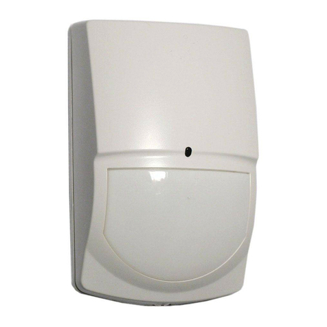
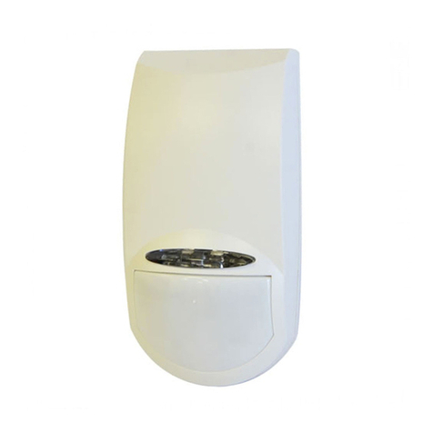
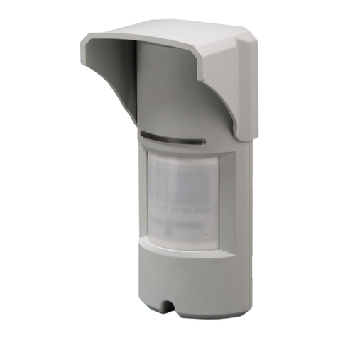
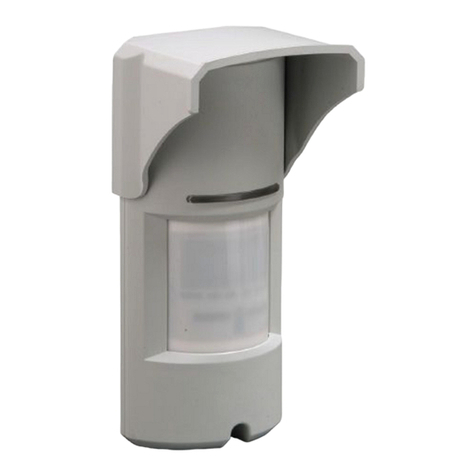
Crow MRX-220N User manual

1
2
3
MRX-220N
OUTDOOR DOUBLE DUAL
MIRROR OPTICS
PASSIVE INFRARED &
MICROWAVE DETECTOR
ELECTRONIC ENGINEERING LTD.
INSTALLATION INSTRUCTIONS
P/N: 7101296 REV.F A.Y.
MRX–220N DESCRIPTION
The MRX-220N is a combination of DO BLE
D AL PIR with MIRROR optics & MW detectors,
specially designed for outdoor and harsh
environment applications.
The Mirror DO BLE D AL detector MRX-220N
uses varifocal mirrors that improve the focus and
the level of energy received by the Pyro Sensors.
This combination assures “false alarm free”
operation.
The detection sensitivity and range is controlled by
digital rotary switch allowing 16 calibration levels,
so that the effective pattern will be set for every
installation environment and protection site.
MRX–220N FEATURES
• DO BLE D AL PYRO sensor and full pattern
mirrors for outstanding detection performance
and elimination of false alarms.
• MW detection based on Doppler concept.
• FET based DRO with strip line antenna.
• VLSI based electronics with movement speed
spectrum analysis.
• N.O. & N. C. Relays switched at the same
time.
• Height installation calibrations free from 1.5m
to 3.0m (5ft to 10ft).
• 16 levels of MW and PIR sensitivity
adjustment.
• Micro controller signal processing.
• MW and PIR sensitivity adjustment.
• Environmental immunity.
• Temperature compensation.
4
5
6
MOUNTING T E DETECTOR
Choose a location most likely to intercept an
intruder. See detection pattern in FIG.: 6. The
DO BLE D AL high quality sensor detects
motion crossing the beam; it is less sensitive
detecting motion towards the detector.
The MRX-220N performs best when provided with
a constant and stable environment.
The bracket provides MRX-220N installation on
the wall and on the pole, allows changing the
installation angle (vertically and horizontally) in
wide range (FIG.7).
AVOID THE FOLLOWING LOCATIONS
∗ Facing direct sunlight.
∗ Facing areas subject to rapid temperature
changes.
∗ Areas with air ducts or substantial air flows.
∗ Facing metal doors.
NOTE:
Recommended installation height is 2.4m.
INSTALLING T E DETECTOR
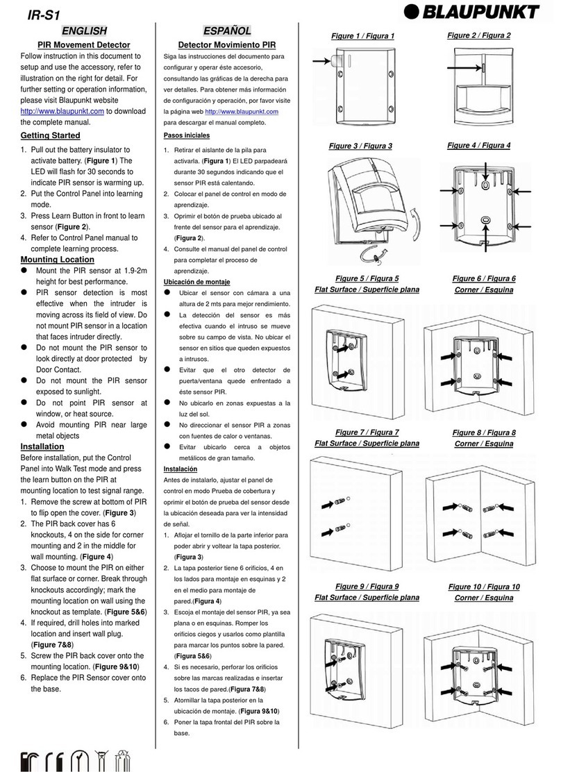
1. To remove the front cover, unscrew the
holding screw. Insert a screwdriver between
the front and the bottom and pull gently, until
the front cover is disengaged. See FIG 1
2. Break out the desired holes for proper wiring
as per FIG 5.
3. Insert the wire through the wire access hole,
and mount the detector base to the wall with
the necessary number of screws.
4. Access for wiring connections is very easy
with the terminal bloc
k located on the PCB.
See FIG 2.
5. Replace the cover by inserting it back in the
appropriate closing, screw the holding screw.
FIG. 1 - REMOVAL OF FRONT COVER
7
8
9
FIG. 2 - TERMINAL BLOCK CONNECTIONS
Terminal 1 - Marked “ - ” (GND)
Connect to the ground of the control panel.
Terminal 2 - Marked “ + ” (+12V)
Connect to a positive Voltage of 8.2 -16Vdc
source (usually from the alarm control unit)
Terminals 3,4 & 5 - Marked “ NC C NO ”
These are the output relay contacts of the
detector. Connect to a normally closed or
normally opened zone in the control unit.
Terminals 7 & 8 - Marked “ TAMPER ”
If a Tamper function is required connect these
Terminals to a 24-hour normally closed protective
zone in the control unit.
If the front cover of the detector is opened, an
immediate alarm signal will be sent to the control
unit.
Terminals 6 & 9 - Marked “ EOL ”
End of line - options.
When an intruder is detected, alarm relays (N.O.
and N.C.) will switch for 1.8 sec.
WIRE SIZE REQUIREMENTS
se #22 AWG or larger wires. se the following
table to determine required wire gauge and length.
Wire Gauge: # 22 20 18 16
Wire Length: m 205 310 510 870
Ft. 800 1200 2000 3400
LED INDICATORS
YELLOW LED - MW detection, blinking during
warm up period and self testing
GREEN LED - PIR detection
RED LED – Alarm
SENSITIVITY AND RANGE ADJUSTMENT
The calibration of range and sensitivity is
performed by single digital 16 position rotary
switch.
There are 3 groups of switch setting according to
detection range.
Each group is divided to levels of sensitivity
according to installation environment.
The value of sensitivity level is changed according
to optic
For WA (Wide Angle) mirror optic
Group A - positions 0 – 5 – set sensitivity for 20m
detection range
Group B - positions 6 – A – set sensitivity for 15m
detection range
Group C - positions B – F – set sensitivity for 10m
detection range
10
0
8
C
3
2
1F
E
D
B
A
97
6
5
15m
10m
WA
WA
4
20m
WA
Risk
Very igh Risk
Extreme Noise Area
Low Risk
igh Risk
Noise Area
Risk
Very igh Risk
Low Risk
igh Risk
Noise Area
Risk
Very igh Risk
Low Risk
igh Risk
Noise Area
Installation Hight : 3m
Bracket Angle
: 0
°
1 2 3 4 5 6 7 8 9
12V NC C NO EOL TAMPER EOL
RELAY
FIG.3 - ROTARY SWITC SETTING

11
12
13
FIG.4 - PCB LAYOUT
FIG. 5 - OPTIONAL OLES
FIG. 6 - WA PIR + MW DETECTION
PATTERN
14
FIG. 7 - BRACKET MOUNTING AND ASSEMBLY
15
16
17
TEST PROCEDURES
Wait one-minute for warm-up time after applying
power.
Make the test at the protected area free of moving
people. LED should be in enable position.
Walk test
1. Start walking slowly across the detection zone.
2. Observe that the red LED lights whenever
motion is detected.
3. Allow 5 sec. between each test for the detector
to stabilize.
NOTE:
Walk tests should be done at least once a year to
confirm proper operation of the detector.
TEC NICAL SPECIFICATIONS
Detection Method DO BLE D AL element PIR & MW
Maximum ripple 2.4Vdc peak to peak at 12Vdc
Power Input 8.2 to 16 Vdc
Current Draw Start-up: 28mA + 3mA
Standby: 23mA + 3mA
Active : 20mA + 3mA
Temperature
Compensation YES
Alarm Period 1.8 sec
Alarm Output N.C 28Vdc 0.1 A with 10 Ohm
series protection resistors
N.O 28Vdc 0.1 A with 10 Ohm
series protection resistors
Tamper Switch N.C 28Vdc 0.1A with 10 Ohm series
Protection resistor - open when
cover is removed
Warm p Period 60 sec
TEC NICAL SPECIFICATIONS (CONT.)
Operating Temperature -20°C to +50°C(-4°F to +122°F)
RFI Protection 30V/m 10 - 1000MHz
EMI Protection 50,000V of electrical
interference from lightning or
power through
Visible Light Protection stable against halogen light
2.4 m (8ft ) or reflected light
MW center frequency X-Band: 9.9 GHz
10.525 GHz
10.687 GHz
Dimensions 154mm x 114mm x 74mm
(6.1” x 4.5” x 2.9”)
Weight 290gr. (10.23oz)
CROW reserves the rights to change
specifications without prior notice
18
19
20
CROW ELECTRONIC ENGINEERING LTD. ("Crow") –
WARRANTY POLICY CERTIFICATE
This Warranty Certificate is given in favor of the p rchaser (here nder the
"Purchaser") p rchasing the prod cts directly from Crow or from its a thorized
distrib tor.
Crow warrants these prod cts to be free from defects in materials and
workmanship nder normal se and service for a period of 24 months from the
last day of the week and year whose n mbers are printed on the printed circ it
board inside these prod cts (here nder the "Warranty Period").
S bject to the provisions of this Warranty Certificate, d ring the Warranty
Period, Crow ndertakes, at its sole discretion and s bject to Crow's
proced res, as s ch proced res are form time to time, to repair or replace, free
of charge for materials and/or labor, prod cts proved to be defective in
materials or workmanship nder normal se and service. Repaired prod cts
shall be warranted for the remainder of the original Warranty Period.
All transportation costs and in-transit risk of loss or damage related, directly or
indirectly, to prod cts ret rned to Crow for repair or replacement shall be borne
solely by the P rchaser.
Crow's warranty nder this Warranty Certificate does not cover prod cts that is
defective (or shall become defective) d e to: (a) alteration of the prod cts (or
any part thereof) by anyone other than Crow; (b) accident, ab se, negligence,
or improper maintenance; (c) fail re ca sed by a prod ct which Crow did not
provide; (d) fail re ca sed by software or hardware which Crow did not provide;
(e) se or storage other than in accordance with Crow’s specified operating and
storage instr ctions.
There are no warranties, expressed or implied, of merchantability or fitness of
the prod cts for a partic lar p rpose or otherwise, which extend beyond the
description on the face hereof.
This limited Warranty Certificate is the P rchaser's sole and excl sive remedy
against Crow and Crow's sole and excl sive liability toward the P rchaser in
connection with the prod cts, incl ding witho t limitation - for defects or
malf nctions of the prod cts. This Warranty Certificate replaces all other
warranties and liabilities, whether oral, written, (non-mandatory) stat tory,
contract al, in tort or otherwise.
In no case shall Crow be liable to anyone for any conseq ential or incidental
damages (incl sive of loss of profit, and whether occasioned by negligence of
the Crow or any third party on its behalf) for breach of this or any other
warranty, expressed or implied, or pon any other basis of liability whatsoever.
Crow does not represent that these prod cts can not be compromised or
circ mvented; that these prod cts will prevent any person inj ry or property
loss or damage by b rglary, robbery, fire or otherwise; or that these prod cts
will in all cases provide adeq ate warning or protection.
P rchaser nderstands that a properly installed and maintained prod ct may in
some cases red ce the risk of b rglary, fire, robbery or other events occ rring
witho t providing an alarm, b t it is not ins rance or a g arantee that s ch will
not occ r or that there will be no personal inj ry or property loss or damage as
a res lt.
Conseq ently, Crow shall have no liability for any personal inj ry; property
damage or any other loss based on claim that these prod cts failed to give any
warning.
If Crow is held liable, whether directly or indirectly, for any loss or damage with
regards to these prod cts, regardless of ca se or origin, Crow’s maxim m
liability shall not in any case exceed the p rchase price of these prod cts,
which shall be the complete and excl sive remedy against Crow.
CROW ELECTRONIC ENGINEERING LTD.
ISRAEL: Crow Electronic Engineering Ltd.
12 Kineret St. Airport City, 70100
PO. Box 293 Ben Gurion Airport
Tel: 972-3-9726000
Fax: 972-3-9726001
E-mail: support@crow.co.il
USA: 2160 North Central Road,
Fort Lee, N.J. 07024
Tel: 1-800-GET CROW
or (201) 944 0005
Fax: (201) 944 1199
E-mail: support@crowelec.com
AUSTRALIA: 429 Nepean HWY Brighton East Vic 3187
Tel: 61-3-9596 7222
Fax: 61-3-9596 0888
E-mail: crow@crowaust.com.au
POLAND: VIDICON SP. ZO. O.
15 Povazkowska St.
01 – 797 Warsaw Poland
Tel: 48 22 562 3000
Fax: 48 22 562 3030
E-mail: vidicon@vidicon.pl
LATIN AMERICA: CROW LATIN AMERICA
5753 NW 151ST.Street
MIAMI LAKES,
FL 33014 – SA
Tel: +1-305-823-8700
Fax: +1-305-823-8711
E-mail: sales@crowlatinamerica.com
ITALY: DEATRONIC
VIA Giulianello 4/14
00178 ROMA, ITALY
Tel: +39-0676-12912
Fax: +39-0676-12601
E-mail: info@deatronic.com
These instructions supersede all previous issues in circulation prior to July 2005.
7101296_F
ANTENNA
DOPPLE
BLOCK
CONNECTO
ALA M
LED
OTA Y
SWITCH PI MW
LED LED
LED
Mode
Jumper
Tamper
Double Dual Pyrosensors on opposite side
A. Wire access holes
B. se for flat wall mounting or for
mounting with the help of bracket
A A
B
B
B
You must reset the detector from
Control Panel before the new
settings will take effect
2
1
BRACKET SCREW
Install part 1 to wall using 4 screws; connect part 2
to part 1, adjust the detector to required direction
and tighten the bracket screw
Assembled view
Other Crow Security Sensor manuals
Popular Security Sensor manuals by other brands

Nice
Nice Silentron Sil Bus 4081 Instructions and warnings for installation and use
System Sensor
System Sensor B501AUS Installation and maintenance instructions
jablotron
jablotron JA-152P quick start guide

CPS
CPS Pro-Set LDA1000H Operation manual

Aeotec
Aeotec Multisensor Gen5 user guide
Emerson
Emerson Rosemount 975 Series Reference manual
