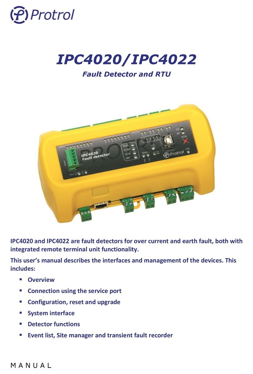
Protrol IPC4020 User manual

M A N U A L
IPC4020/IPC4022
Fault Detector and RTU
IPC4020 and IPC4022 are fault detectors for over current and earth fault, both with
integrated remote terminal unit functionality.
This user’s manual describes the interfaces and management of the devices. This
includes:
▪Overview
▪Connection using the service port
▪Configuration, reset and upgrade
▪System interface
▪Detector functions
▪Event list, Site manager and transient fault recorder
▪Commissioning and testing

IPC402x-UM-2209-1-2.x.x (en)
Ensto Protrol AB Phone: +46 31 45 82 00
Alfagatan 3 internet: www.protrol.se
431 49 Mölndal, SWEDEN 2e-mail: info@protrol.se
Table of Contents
1Safety Information ___________________________________________________________ 4
2Abbreviations _______________________________________________________________ 5
3Firmware ___________________________________________________________________ 5
4Overview ___________________________________________________________________ 6
4.1 Front Panel –HMI _______________________________________________________________ 7
LED Indicators ________________________________________________________________________________ 7
4.1.1 Push-button for Local Acknowledge ______________________________________________________ 8
4.2 Startup ________________________________________________________________________ 8
4.3 Internal Supervision _____________________________________________________________ 9
4.4 Interfaces______________________________________________________________________ 9
4.4.1 RS485/RS422 port for IEC 60870-5-101 Slave and PDCIO ______________________________________ 9
4.4.2 RS485-port för IEC 60870-5-101 Master (option) ___________________________________________ 10
4.4.3 Ethernet Interface for IEC 60870-5-104 and Service Port _____________________________________ 10
4.4.4 USB Port ___________________________________________________________________________ 10
4.4.5 Secondary Current Inputs ______________________________________________________________ 10
4.4.6 Power Supply________________________________________________________________________ 10
5Service Interface ____________________________________________________________ 11
5.1 Connecting using Ethernet _______________________________________________________ 11
5.2 Connecting using USB ___________________________________________________________ 12
5.3 Login_________________________________________________________________________ 13
5.4 Start Tab and Device Information__________________________________________________ 13
6Configuration and Settings____________________________________________________ 14
6.1 Device Settings –Unit ___________________________________________________________ 18
6.2 Time synchronisation –NTP ______________________________________________________ 18
7Remote Control Interface _____________________________________________________ 20
7.1 Events, Queues and Interrogation _________________________________________________ 21
7.2 General Settings –Communication ________________________________________________ 22
7.2.1 Communication –Ethernet_____________________________________________________________ 22
7.2.2 Communication –IEC 60870-5-101/104 __________________________________________________ 22
7.2.3 IEC 60870-5-101 master - OPTIONAL _____________________________________________________ 25
7.3 Binary inputs –I/O-addressing –Binary Inputs _______________________________________ 28
7.3.1 Binary Inputs –Input 1-16/22/37________________________________________________________ 29
7.3.2 Binary Inputs –Detector m_____________________________________________________________ 30
7.3.3 Binary Inputs –IEC 60870-5-101/-104 Master______________________________________________ 32
7.3.4 Binary Inputs –PDCIO and PBI __________________________________________________________ 32
7.4 Binary outputs –I/O-addressing –Binary Outputs ____________________________________ 33
7.4.1 Binary Outputs –Output 1-8/13/22______________________________________________________ 34
7.4.2 Binary Outputs –Detector m___________________________________________________________ 35
7.4.3 Binary Outputs –PDCIO and PBO________________________________________________________ 35

IPC402x-UM-2209-1-2.x.x (en)
Ensto Protrol AB Phone: +46 31 45 82 00
Alfagatan 3 internet: www.protrol.se
431 49 Mölndal, SWEDEN 3e-mail: info@protrol.se
7.5 Analog Inputs (I/O-addressing –Analog Inputs) ______________________________________ 36
7.5.1 Analog Inputs –Internal _______________________________________________________________ 37
7.5.2 Analog Inputs –Detector m____________________________________________________________ 38
7.5.3 Analog Inputs –PDCIO and PAI _________________________________________________________ 40
8Detector Functions __________________________________________________________ 41
8.1 General ______________________________________________________________________ 41
8.2 Detection states _______________________________________________________________ 41
8.2.1 Evaluation of Earth Faults______________________________________________________________ 42
8.2.2 Evaluation of Transient and Arcing Faults _________________________________________________ 43
8.3 Settings - Common _____________________________________________________________ 44
8.4 Settings - I/O Settings ___________________________________________________________ 45
8.5 Detector Settings –Detector n ____________________________________________________ 46
8.5.1 Overcurrent_________________________________________________________________________ 46
8.5.2 Earth Fault, General __________________________________________________________________ 47
8.5.3 Earth Fault Protrol____________________________________________________________________ 47
8.5.4 Non-Directional Earth Fault ____________________________________________________________ 48
8.6 Phase Break ___________________________________________________________________ 49
8.6.1 Auto reclosing –OPTION ______________________________________________________________ 50
9Event log and Site Manager ___________________________________________________ 51
9.1 Event log –Event log ____________________________________________________________ 51
9.2 Site Manager __________________________________________________________________ 52
10 Transient Fault Recorders –TFR________________________________________________ 55
11 Upgrade of Firmware ________________________________________________________ 59
11.1 PDCIO ______________________________________________________________________ 59
12 Checklist for Commissioning and Testing ________________________________________ 60
13 References_________________________________________________________________ 63

IPC402x-UM-2209-1-2.x.x (en)
Ensto Protrol AB Phone: +46 31 45 82 00
Alfagatan 3 internet: www.protrol.se
431 49 Mölndal, SWEDEN 4e-mail: info@protrol.se
1 Safety Information
Only certified electricians are allowed to perform installation work.
National and local security guidelines must be followed.
Always short circuit the secondary conductors of the current transformers during maintenance or
testing.
If the secondary circuit of the CT’s are opened or if their earthing point is missing or removed
while the primary side is energized, high voltages can be generated. In worst case these voltages
can be deadly and damage isolation material. Energization of the CT’s primary side is not
permitted as long as the secondary side is open or not earthed.
Dangerous voltages can be present on the terminals, also when power is removed from
the device.
Violation against the security guidelines can lead to fatalities, personal injury or considerable
damage to equipment.
Avoid removing the cover of the IPC402x devices. If it is removed, ensure that all electronic
components are protected against electrostatic discharge, ESD, by proper earthing of both
the device and the personnel performing maintenance.
The device should be connected to protective earth at terminal X4.2.

IPC402x-UM-2209-1-2.x.x (en)
Ensto Protrol AB Phone: +46 31 45 82 00
Alfagatan 3 internet: www.protrol.se
431 49 Mölndal, SWEDEN 5e-mail: info@protrol.se
2 Abbreviations
IPC401x Previous generation fault detectors –IPC4010, -11 and -12
IPC402x IPC4020, IPC4020exp3, IPC4020exp6 or IPC4022
ASDU Application Service Data Unit
COMTRADE Common Transient Data Exchange
DHCP Dynamic Host Configuration Protocol
EF Earth Fault
ESD Electro Static Discharge
OC Overcurrent
RTU Remote Terminal Unit
NTP Network Time Protocol
TFR Transient Fault Record(-er)
3 Firmware
Some of the functions described in this document were introduced in firmware version 1-2.1.0.

IPC402x-UM-2209-1-2.x.x (en)
Ensto Protrol AB Phone: +46 31 45 82 00
Alfagatan 3 internet: www.protrol.se
431 49 Mölndal, SWEDEN 6e-mail: info@protrol.se
4 Overview
IPC402x consists of two or three printed circuit boards; base board, front board and, if applicable, an
expansion board. Overview pictures of IPC4020/IPC4020exp3 and IPC4022 are shown in Figure 1 and
Figure 2. More detailed descriptions of the devices can be found in the datasheets for the devices [1][2].
IA1
2
X21
1
IB1
X22
2
1
IC2
X33
IB2
X32
IA2
X31
1 1 12 22
Expansion
Expansion module, 2 x 3 currents
IC1
X23
1 2
Link
Act.
Ethernet
RJ45
IA
2
X1
1
IB
X2
2
1
IC
X3
1 2 PWR
PWR
+-
GND321
X4
Binary inputs Binary outputs
867 5 4 2
31
C
65432 1
X6
9 8 7 X10
2 1
C
321
X9
3
C
321
X5 2 1
Option W
9
X12
RS232
X11
RS485
1
2
4
5
3
TERM ACN
OC
EF
1 2 3 4
EX USB
Type B
Rx/Tx
RxTx
RUN
EVNT IRF
AUX
IPC4022
t°
Figure 1. Overview IPC4020 with expansion for two extra detector functions (to the left). The outputs of contacts
X8 and X10 are routed to more powerful relays.
Link
Act.
Ethernet
RJ45
IA
2
X1
1
IB
X2
2
1
IC
X3
1 2 PWR
PWR
+-
GND321
X4
Binary inputs Binary outputs
867 5 4 2
31
C
6 5 4 32 1
X6
98 7 X10
2 1
C
321
X9
3
C
3 2 1
X5 2 1
Option W
9
X12
RS232
X11
RS485
1
2
4
5
3
TERM ACN
OC
EF
1 2 3 4
EX USB
Type B
Rx/Tx
RxTx
RUN
EVNT IRF
AUX
IPC4022
t°
Figure 2. Overview IPC4022. The outputs on contact X10 are routed to more powerful relays.
The only normal reason to remove the front cover of the devices is to check the identification stickers that
are located on the printed circuit boards, if requested. Each circuit board has a unique identity with the
following format, see example beneath.
Manufacturing year and week: 1906
Batch identity: 46539
Sequence number: P0098

IPC402x-UM-2209-1-2.x.x (en)
Ensto Protrol AB Phone: +46 31 45 82 00
Alfagatan 3 internet: www.protrol.se
431 49 Mölndal, SWEDEN 7e-mail: info@protrol.se
The sticker of the front board is located on the rear side of the board. It is not necessary to remove the
front board to be able to see the identity number when needed during support cases or reclaims.
Figure 3. Example board identity.
4.1 Front Panel –HMI
LED Indicators
There are various LED indicators on the front panel for inputs, outputs, communication ports and status
purposes.
Figure 4. Front panel of IPC4020.
Each binary input and output have a LED above its screw terminal and reflects the position of the
input/output. Voltage on an input activates the LED. Closed relay output activates the LED.

IPC402x-UM-2209-1-2.x.x (en)
Ensto Protrol AB Phone: +46 31 45 82 00
Alfagatan 3 internet: www.protrol.se
431 49 Mölndal, SWEDEN 8e-mail: info@protrol.se
The table beneath describes the other LED indicators on the front panel.
LED
Description
PWR
Green diode indicating that the device is powered up
RUN
Green diode normally flashing at 0.5 Hz frequency
EVNT
Yellow diode indicating that there is an unsent telegram in the queue for slave transmission
on the system interface
AUX
Yellow diode that normally indicates that the device is handling a frequency deviation
IRF
Red diode that indicates internal fault
USB
Yellow diode indicating a connected USB port
OC
Red diode indicating that an overcurrent has been detected
EF
Red diode indicating that an earth fault has been detected
Tx Master
Yellow diode indicating that a telegram is being sent on the serial master interface
Rx Master
Yellow diode indicating that a telegram is being received on the serial master interface
Tx Slave
Yellow diode indicating that a telegram is being sent on the serial slave interface
Rx Slave
Yellow diode indicating that a telegram is being received on the serial slave interface
Tx/Rx (USB)
Dual-coloured green-red diode which alternates when there is traffic on the USB port.
EX1
Yellow diode indicating that Detector 1 has identified a fault
EX2
Yellow diode indicating that Detector 2 has identified a fault –applies to expanded device
EX3
Yellow diode indicating that Detector 3 has identified a fault –applies to expanded device
EX4
Yellow diode that in normal configuration indicates start fault detection, detector 1-3
Some LEDs, such as AUX and EX1-4, can have other functionality for certain option choices.
4.1.1 Push-button for Local Acknowledge
There is a push-button, ACN, on the far right of the front panel for local acknowledge of the overcurrent
and earth fault indications, and factory reset. Remote acknowledge from the dispatch center and automatic
self-acknowledge after a configurable time delay are described in a separate chapter of this text manual.
4.2 Startup
After a restart of the device, i.e., if there has been a disturbance in DC supply or a restart has been ordered
from remote, inputs and outputs are updated with the current status. Any outputs that were activated
before the restart, return to inactive position unless the conditions for activation are valid.

IPC402x-UM-2209-1-2.x.x (en)
Ensto Protrol AB Phone: +46 31 45 82 00
Alfagatan 3 internet: www.protrol.se
431 49 Mölndal, SWEDEN 9e-mail: info@protrol.se
4.3 Internal Supervision
Internal check of CPU-near hardware and software modules is performed at startup.
▪Memory check –activates IRF
▪Flash memory check –activates IRF
▪Expansion board check –activates IRF
▪Execution of software modules –activates IRF
▪Supervision of external interfaces –rapported in Event Log
Supervision of expansion boards and execution of software modules are performed continuously.
4.4 Interfaces
4.4.1 RS485/RS422 port for IEC 60870-5-101 Slave and PDCIO
IPC402x has a signal interface on the left of the front panel for connection to the remote control center
using the communication protocol IEC 60870-5-101.
This port supports 2-wire (half duplex) communication. It is factory set to 8-E-1, i.e., 8 data bits, even parity
and 1 stop bit. With options where the front panel is modified, it is possible to handle both 4-wire (full
duplex) or RS232 communication.
There is built-in protection for surge voltages. However, cables for communication that may be subjected
to overvoltage must have a primary protection, for example Protrol OVP. As a rule of thumb, one can say
that cables that leave the building / station must be supplemented with a primary protection.
Terminals
Terminal/pin
Short name
Description
X11:1
TX+
Sender (plus)
X11:2
TX-
Sender (minus)
X11:3
RX(TX)+
Receiver (plus), (also sender when 2-wire)
X11:4
RX(TX)-
Receiver (minus), (also sender when 2-wire)
X11:5
TERM
Termination for receiver. Connect to X11:4 for activation
Terminering
The first (master) and last device (last slave) on the communication line should be terminated. This is
done on IPC402x by short-circuiting X11:4 and X11:5.
The terminals X11:3 and X11:4 are used for 2-wire communication. Configuration according to Chapter 7.2.
The terminal X11 is also used as the physical interface when the expansion device PDCIO is used. PDCIO is
connected to the terminals X11:3 and X11:4 in the same manner as when 2-wire-communication is
employed for communication with the remote control centre using IEC 60870-5-101.
Observe that PDCIO can only be used if IEC 60870-5-104 is used for communication with the remote control
centre.

IPC402x-UM-2209-1-2.x.x (en)
Ensto Protrol AB Phone: +46 31 45 82 00
Alfagatan 3 internet: www.protrol.se
431 49 Mölndal, SWEDEN 10 e-mail: info@protrol.se
4.4.2 RS485-port för IEC 60870-5-101 Master (option)
IPC4020 has another terminal X13 on the left lower side, where additional units that communicate with IEC
60870-5-101 can be connected. The port only supports 2-wire communication (half duplex). It is factory set
to 8-E-1, i.e., 8 data bits, even parity and 1 stop bit. This function and port are not available on IPC4022.
Note that the IEC 60870-5-101 Master function is an option and is ordered separately, see datasheet [1].
There is built-in protection for surge voltages. However, cables for communication that may be subjected
to overvoltage must have a primary protection, for example Protrol OVP. As a rule of thumb, one can say
that cables that leave the building / station must be supplemented with a primary protection.
Terminals
Terminal/pin
Short name
Description
X13:1
RX/TX+
Sender/Receiver (plus)
X13:2
RX/TX-
Sender/Receiver (minus)
X13:3
TERM
Line termination. Connect to X13:2 for activation.
Terminering
The first (master) and last device (last slave) on the communication line should be terminated. This is
done on IPC402x by short-circuiting X13:2 and X13:3.
4.4.3 Ethernet Interface for IEC 60870-5-104 and Service Port
There is an Ethernet interface, RJ45 10/100Base - TX Full Duplex, for communication via IEC 60870-5-104
and the remote control centre.
This interface is also used as a service port, i.e., for connecting a service computer using TCP / IP and
accessing the built-in web interface of IPC402x.
4.4.4 USB Port
IPC402x is equipped with a service port for USB Type B. The port is located on the right of the front panel
next to the local acknowledge push-button, ACN.
4.4.5 Secondary Current Inputs
Current terminals for phase current transformers are found in the following locations:
▪Detector 1: Terminals X1-X3 between the RJ45 connector for Ethernet and the terminal for power
supply.
▪Detector 2: Terminals X21-X23, lower side of the expansion module (left side of IPC4020exp3).
▪Detector 3: Terminals X31-X33, upper side of the expansion module (left side of IPC4020exp3).
4.4.6 Power Supply
IPC402x requires an external power supply of 24-48 VDC which is connected to terminal block X4. The
connection is not polarity sensitive.
The unit must be connected to protective ground via X4.2.

IPC402x-UM-2209-1-2.x.x (en)
Ensto Protrol AB Phone: +46 31 45 82 00
Alfagatan 3 internet: www.protrol.se
431 49 Mölndal, SWEDEN 11 e-mail: info@protrol.se
5 Service Interface
The built-in web server in IPC402x gives authorized access to all settings, status information, file transfer
and event lists, either via Ethernet RJ45 or USB type B. Protrol recommends using Chrome or Firefox web
browsers.
5.1 Connecting using Ethernet
The prerequisite for connecting via Ethernet is that the service computer has IP settings that match, i.e.,
the same subnet and subnet mask, with those of the IPC device that you want to connect to.
An IPC402x is supplied either with factory settings or with order-specific settings. The factory settings are as
follows:
Parameter
Value
IP address
192.168.0.31
Net mask
255.255.255.0
Standard gateway
192.168.0.1
The above settings mean that the IPC is accessible via computers with addresses within the 192.168.0.x
range, or redirected addresses via the gateway/router.

IPC402x-UM-2209-1-2.x.x (en)
Ensto Protrol AB Phone: +46 31 45 82 00
Alfagatan 3 internet: www.protrol.se
431 49 Mölndal, SWEDEN 12 e-mail: info@protrol.se
5.2 Connecting using USB
It is also possible to connect using USB type B. to do so, a separate software, Protrol USB Bridge for
Windows 7/10, is needed. This is available on Ensto Protrol's website, together with a link to download
necessary drivers. Below is a brief description of how to connect using this software.
1. Start Protrol USB Bridge.
a. If an IPC402x is found by the program, the current COM port is displayed.
See the left image in Figure 5.
2. Click on Open serial port.
a. If the connected, the other buttons will light up.
See the right image in Figure 5.
3. Open the default browser by clicking Open web browser.
a. To start the web browser manually, please enter
127.0.0.1:20080/ in the address bar.
Figure 5. When starting Protrol USB Bridge, the left picture is displayed. Select the proposed COM port and click
Open serial port. After this, it is possible to open the default browser by pressing Open web browser
(right image).

IPC402x-UM-2209-1-2.x.x (en)
Ensto Protrol AB Phone: +46 31 45 82 00
Alfagatan 3 internet: www.protrol.se
431 49 Mölndal, SWEDEN 13 e-mail: info@protrol.se
5.3 Login
After connecting to the IPC402x device, a login screen is displayed. This includes information about the
connected Protrol device and the input field for logging in.
Figure 6. The login field of the web server.
The following standard users can be selected:
User
Password
User properties
status
status
Displaying settings
Download of disturbance files
config
config
Display / change of normal settings
Download of disturbance files
Firmware upgrade
admin
availability
Same as config, and in addition user administration and password
Display / change of special settings
Please observe that special characters cannot be used for passwords.
5.4 Start Tab and Device Information
After logging in, the Start tab is displayed. This includes status and information about the connected device,
as well as tabs for other functions.
At the bottom of all web pages, even on the login page, there is the unit's unique ID number and version on
software, see Figure 6. Copy the information field and attach it to the support case or complaint.
The service interface has a built-in timeout, which means that automatic logout is done after a period of
inactivity.

IPC402x-UM-2209-1-2.x.x (en)
Ensto Protrol AB Phone: +46 31 45 82 00
Alfagatan 3 internet: www.protrol.se
431 49 Mölndal, SWEDEN 14 e-mail: info@protrol.se
6 Configuration and Settings
Configuration is done using the web interface. See chapter 4 for details on connection to the device and its
web interface. The majority of the PDCIO parameters are configured in IPC4020.
All settings can be found on the Config tab:
Write/Save settings:
•When new settings are to be saved and activated in the IPC unit, press the Write to unit button.
•The settings are then transferred to the device and it then restarts automatically. If PDCIO is
connected, its parameters will be transferred at startup of the IP device and PDCIO will
subsequently be restarted. Note! It is important that the PDCIO device is connected and functions
normally when pressing the Write to unit button, otherwise new settings will not be transferred to
the device.
•You need to login again after the restart.
•The settings can also be saved to a local file using the Save as…. button.
Read/Open settings:
•If settings are to be read from the device, press the Read from unit button.
•Settings saved on file are loaded using the Open…. button.

IPC402x-UM-2209-1-2.x.x (en)
Ensto Protrol AB Phone: +46 31 45 82 00
Alfagatan 3 internet: www.protrol.se
431 49 Mölndal, SWEDEN 15 e-mail: info@protrol.se
Reset settings:
•IPC402x is delivered either with Protrol's factory defaults or with specific customer settings
(delivery defaults) according to agreement between Ensto Protrol and the customer.
•Reset to factory / customer settings is made on the System tab.
Note that passwords for the different login levels are also reset.
Internet settings, the device's IP address, etc., are not reset.
This also applies to IP addresses for IEC 60870-5-104.
•Complete reset to factory / customer settings:
A complete reset, including all Internet settings, can be done in two different ways:
1. From web interface.
Note that there is a great risk of losing the ability to remotely connect to the device after
the reset, depending on the changed IP address and other internet settings!
In order to be able to make a complete reset via the web interface, the user must log in as
the administrator admin.
On the System tab you first activate specialist mode, by pressing the button Display
specialist settings. After that the button for full reset is displayed, Reset settings to
delivery / factory defaults.

IPC402x-UM-2209-1-2.x.x (en)
Ensto Protrol AB Phone: +46 31 45 82 00
Alfagatan 3 internet: www.protrol.se
431 49 Mölndal, SWEDEN 16 e-mail: info@protrol.se
2. Using ACN button.
A full reset can also be done using the acknowledge button (ACN) on the front card by
following these steps:
▪Restart the device by power cycling it.
▪Press and hold the ACN button when the first LEDs light up (IRF etc.).
▪After a while the EX LEDs are lit. Release the ACN button before they have counted
down entirely.
- Avoid a reset by pressing the ACN button until the device is in normal operation.
▪The unit now resets the settings and then restarts.
1
2

IPC402x-UM-2209-1-2.x.x (en)
Ensto Protrol AB Phone: +46 31 45 82 00
Alfagatan 3 internet: www.protrol.se
431 49 Mölndal, SWEDEN 17 e-mail: info@protrol.se
User administration:
Activation/deactivation of users and replacement of passwords are made on the Config/Accounts tab.
Figur 1: Administration of accounts can be done when the user is logged in as admin.
The administrator can activate/deactivate all accounts except for the admin account. Please observe that
the passwords can only to consist of capital letters, lower case letters and the numbers 0-9. Special
characters and other national characters are not allowed.

IPC402x-UM-2209-1-2.x.x (en)
Ensto Protrol AB Phone: +46 31 45 82 00
Alfagatan 3 internet: www.protrol.se
431 49 Mölndal, SWEDEN 18 e-mail: info@protrol.se
6.1 Device Settings –Unit
The IPC device has general settings on the Unit subtab, listed in the table beneath. The Watchdog relay
closes when all is normal. If there is an internal fault, the relay opens. If power supply is missing, the relay
will remain open.
Parameter
Description
Range
Factory value
Unit
Unit information:
Site
Site reference1
-
Default
-
FreeText
Free text for extra information
-
-
-
Wathdog output:
Enable
Activation of the Wathdog feature
Yes or No
No
-
Watchdog relay
Choice of relay output
1..8
1
-
PDCIO:2
Enable
Activation of external I/O-module PDCIO
Yes or No
No
-
6.2 Time synchronisation –NTP
IPC402x has support for time synchronization using NTP. Settings can be found on the Config/NTP tab.
Figure 7. Configuration of NTP.
1
If the disturbance recording files shall be visualized using Protrol-Tool, the station name is not allowed to have
spaces. Alternatively, the files must be edited before they can be loaded by the tool.
2
PDCIO is described in details in its own user’s manual [4].

IPC402x-UM-2209-1-2.x.x (en)
Ensto Protrol AB Phone: +46 31 45 82 00
Alfagatan 3 internet: www.protrol.se
431 49 Mölndal, SWEDEN 19 e-mail: info@protrol.se
Parameter
Description
Range
Factory value
Unit
Enable NTP
Activation of NTP
Yes or No
No
-
UTC offset
Adjustment, offset, of time
-60..60
0
min
IP address primary NTP
Primary NTP server
-
0.0.0.0
-
IP address secondary NTP
Secondary NTP server
-
0.0.0.0
-
IPC402x time is used for time stamping of indications, events, and disturbance recordings. The time
resolution is 1 ms.
When NTP is activated, time synchronisation using IEC 60870-101/-104 is disabled.

IPC402x-UM-2209-1-2.x.x (en)
Ensto Protrol AB Phone: +46 31 45 82 00
Alfagatan 3 internet: www.protrol.se
431 49 Mölndal, SWEDEN 20 e-mail: info@protrol.se
7 Remote Control Interface
IPC402x includes an integrated RTU (Remote Terminal Unit) function.
All physical binary and analog inputs can be configured to communicate values to a remote control system.
Physical outputs can be set up to be controlled from remote.
Also events from detector functions as well as various objects for activation (e.g. Autoreclosure) and objects
for acknowledgment can be assigned to the remote control system.
IPC402x supports the communication protocols IEC 60870-5-101 and IEC 60870-5-104.
In addition, there is an option which makes it possible to use IPC4020 as a local -101 Master. With this
option it is possible to connect several -101 slaves to IPC4020 and access them in the remote control
center. This option is not available for IPC4022.
Please observe that IEC 60870-5-101 Master is optional and must be ordered separately, refer to the
datasheet [1].
IEC 60870-5-101:
•Physical interface for IEC 60870-5-101 is RS485 (X11) or RS232 (X12 DSUB9, optional).
•Both 2 and 4 wire communication is supported for RS485 communication.
•Terminate RS485 by short-circuiting inputs 4 and 5 on the X11 terminal. Only the last device should
be terminated if there additional IPC402x on the same RS485 loop.
IEC 60870-5-104:
•Physical interface for IEC 60870-5-104 is RJ45 10/100Base –TX Full Duplex.
IEC 60870-5-101 Master - OPTIONAL:
•Physical interface for IEC 60870-5-101 Master is 2 wire communication via RS485 (X13).
•Refer to kapitel 4.4.2 for detailed information regarding the physical connection.
•Please observe that IEC 60870-5-101 Master is optional, refer to the datasheet [1].
For more information regarding settings for communication, objects and more, see the following chapters.
A general description on how to configure IPC402x can be found in Chapter 6.
Other manuals for IPC4020
1
This manual suits for next models
1
Table of contents
Other Protrol Security Sensor manuals
Popular Security Sensor manuals by other brands
Siemens
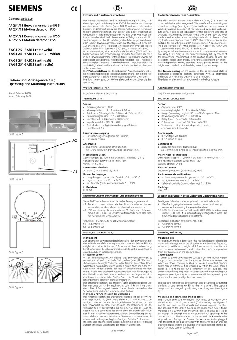
Siemens AP 251/11 Operating and mounting instructions
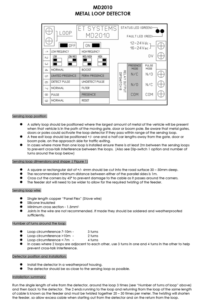
Et system
Et system MD2010 manual
Powerfix Profi
Powerfix Profi 4-IN-1 MULTI-DETECTOR Operation and safety notes

PCB Piezotronics
PCB Piezotronics TORKDISC 5302D-02A/012AC080AT Installation and operating manual
jablotron
jablotron JA-150P PET manual
Halma
Halma Apollo XP95 I.S. manual
