Protrol IPC4020 User manual

M A N U A L
IPC4020/IPC4022
Fault Detector and RTU
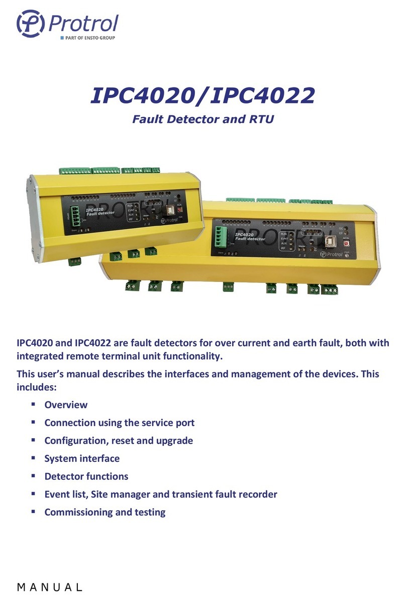
IPC4020 and IPC4022 are fault detectors for over current and earth fault, both with
integrated remote terminal unit functionality.
This user’s manual describes the interfaces and management of the devices. This
includes:
▪Overview
▪Connection using the service port
▪Configuration, reset and upgrade
▪System interface
▪Detector functions
▪Event list, Site manager and transient fault recorder

Ver 1909
Protrol AB Phone: +46 31 45 82 00
Alfagatan 3 internet: www.protrol.se
431 49 Mölndal, SWEDEN 2e-mail: info@protrol.se
▪Commissioning and testing
Table of Contents
Safety Information ___________________________________________________________ 4
Abbreviations _______________________________________________________________ 4
Overview ___________________________________________________________________ 5
3.1 Front Panel –HMI _______________________________________________________________ 6
LED Indicators ________________________________________________________________________________ 6
Push-button for Local Acknowledge (ACN) _________________________________________________________ 7
3.2 Interfaces______________________________________________________________________ 7
RS485/RS422 port for IEC 60870-5-101 Slave _______________________________________________ 7
RS485-port för IEC 60870-5-101 Master (option) ____________________________________________ 8
Ethernet Interface for IEC 60870-5-104 and Service Port ______________________________________ 9
USB Port ____________________________________________________________________________ 9
Secondary Current Inputs _______________________________________________________________ 9
Power Supply_________________________________________________________________________ 9
Service Interface ____________________________________________________________ 10
4.1 Connecting using Ethernet _______________________________________________________ 10
4.2 Connecting using USB ___________________________________________________________ 11
4.3 Login_________________________________________________________________________ 12
4.4 Startup page and device information_______________________________________________ 12
Configuration and Settings____________________________________________________ 13
5.1 Settings –Unit _________________________________________________________________ 15
5.2 Settings –SNTP ________________________________________________________________ 15
Remote Control Interface _____________________________________________________ 16
6.1 General Settings –Communication ________________________________________________ 16
Communication –Ethernet_____________________________________________________________ 16
Communication –IEC 60870-5-101/104 __________________________________________________ 17
6.2 Binary inputs (I/O-addressing –Binary Inputs) _______________________________________ 19
Binary Inputs –Input 1-16 _____________________________________________________________ 20
Binary Inputs –Detector x _____________________________________________________________ 21
6.3 Binary outputs (I/O-addressing –Binary Outputs) ____________________________________ 22
Binary Outputs –Output 1-8 ___________________________________________________________ 22
Binary Outputs –Detector x ____________________________________________________________ 23
6.4 Analog Inputs (I/O-addressing –Analog Inputs) ______________________________________ 24
Analog Inputs –Internal _______________________________________________________________ 25
Analog Inputs –Detector x _____________________________________________________________ 26
Detector Functions __________________________________________________________ 28
7.1 General ______________________________________________________________________ 28

Ver 1909
Protrol AB Phone: +46 31 45 82 00
Alfagatan 3 internet: www.protrol.se
431 49 Mölndal, SWEDEN 3e-mail: info@protrol.se
7.2 Detection states _______________________________________________________________ 28
Evaluation of Earth Faults ______________________________________________________________________ 29
Evaluation of Transient and Arcing Faults _________________________________________________________ 30
7.3 Settings - Common _____________________________________________________________ 31
7.4 Settings –Detector n ____________________________________________________________ 32
Current Transformer__________________________________________________________________ 32
Overcurrent_________________________________________________________________________ 32
Earth Fault, General __________________________________________________________________ 32
Earth Fault Protrol____________________________________________________________________ 33
Non-Directional Earth Fault ____________________________________________________________ 33
7.5 Phase Break ___________________________________________________________________ 34
Event log and Site Manager ___________________________________________________ 36
8.1 Event log –Event log ____________________________________________________________ 36
8.2 Site Manager __________________________________________________________________ 37
Transient Fault Recorders –TFR________________________________________________ 39
Upgrade of Firmware ________________________________________________________ 43
Checklist for Commissioning and Testing ________________________________________ 44
References_________________________________________________________________ 46

Ver 1909
Protrol AB Phone: +46 31 45 82 00
Alfagatan 3 internet: www.protrol.se
431 49 Mölndal, SWEDEN 4e-mail: info@protrol.se
Safety Information
Avoid removing the cover of the IPC402x devices. If it is removed, ensure that all electronic
components are protected against electrostatic discharge, ESD, by proper grounding of both the
device and the person performing maintenance.
Always short circuit the secondary conductors of the current transformers during maintenance or
testing.
The device should be connected to protective grounding through contact X4.2.
Abbreviations
IPC401x Previous generation fault detectors –IPC4010, -11 and -12
IPC402x IPC4020, IPC4020exp or IPC4022
ASDU Application Service Data Unit
COMTRADE Common Transient Data Exchange
DHCP Dynamic Host Configuration Protocol
EF Earth Fault
OC Overcurrent
RTU Remote Terminal Unit
SNTP Simple Network Time Protocol
TFR Transient Fault Record(-er)

Ver 1909
Protrol AB Phone: +46 31 45 82 00
Alfagatan 3 internet: www.protrol.se
431 49 Mölndal, SWEDEN 5e-mail: info@protrol.se
Overview
IPC402x consists of two or three printed circuit boards; base board, front board and, if applicable, an
expansion board. Overview pictures of IPC4020/IPC4020exp and IPC4022 are shown in Figure 1 and
Figure 2. Overview IPC4022. The output 3 is routed to a power relay.
More detailed descriptions of the devices can be found in the datasheet for each device [1][2].
IA1
2
X21
1
IB1
X22
2
1
IC1
X23
1 2
EXPANSION
IC2
X33
IB2
X32
IA2
X31
1 1 12 22
IPCEXP
Binary inputs
9
Link
Act.
Ethernet
RJ45
IA
C1A
2
X1
1
IB
X2
C1A
2
1
IC
X3
C1A
1 2 PWR
PWR
+-
GND321
X4
Binary inputs Binary outputs
7
16 1415 13 12 10
11C
12 3 45678 9
X5
867 5 4 2
31
C
45678 9
X6
12 3 X7
8
C
123 X8
6 5
C
1 2 3 X9
4 3
C
123 X10
2 1
C
1 2 3
TxL
RxL
1 2
X13
RS485 3
EXPANSION
ACN
q
USB
Typ B
Rx/Tx
X11
RS485
TxL
RxL
1
2
4
5
31 2 3 4
EX
TERM
Expansion module
RUN
EVNT IRF
AUX
IPC4020
OC
EF
X12
RS232
Figure 1. Overview IPC4020 with expansion for two extra detector functions (to the left). The outputs 1, 2, 5 and 6
are routed to power relays.
ACN
Link
Act.
Ethernet
RJ45
IA
2
X1
1
IB
X2
2
1
IC
X3
1 2 PWR
PWR
+-
GND321
X4
Binary inputs
q
Binary outputs
867 5 4 2
31
C
6 5 4 32 1
X6
98 7 X10
2 1
C
321
USB
Type B
Rx/Tx
X11
RS485
TxL
RxL
1
2
4
5
3
RUN
EVNT IRF
AUX
IPC4022
OC
EF 1 2 3 4
EX
TERM
X9
3
C
3 2 1
X5 2 1
Option W
9
X12
RS232
Figure 2. Overview IPC4022. The output 3 is routed to a power relay.
The only normal reason to remove the front cover of the devices is to check the identification stickers that
are located on the printed circuit boards. Each circuit board has a unique identity with the following format,
see example beneath.
Manufacturing year and week: 1906
Batch identity: 46539
Sequence number: P0098

Ver 1909
Protrol AB Phone: +46 31 45 82 00
Alfagatan 3 internet: www.protrol.se
431 49 Mölndal, SWEDEN 6e-mail: info@protrol.se
The sticker of the front board is located on the rear side of the board. It is not necessary to remove the
front board to be able to see the identity number when needed during support cases or reclaims.
Figure 3. Example board identity.
3.1 Front Panel –HMI
LED Indicators
There are various LED indicators on the front panel for inputs, outputs, communication ports and status
purposes.
Figure 4. Front panel of IPC4020.
Each binary input and output have a LED above its screw terminal and reflects the position of the
input/output. Voltage on an input activates the LED. Closed relay output activates the LED.

Ver 1909
Protrol AB Phone: +46 31 45 82 00
Alfagatan 3 internet: www.protrol.se
431 49 Mölndal, SWEDEN 7e-mail: info@protrol.se
The table beneath describes the other LED indicators on the front panel.
LED
Description
PWR
Green diode indicating that the device is powered up
RUN
Green diode normally flashing at 0.5 Hz frequency
EVNT
Yellow diode indicating that there is an unsent telegram in the queue for slave transmission
on the system interface
AUX
Yellow diode that normally indicates that the device is handling a frequency deviation
IRF
Red diod that indicates internal fault
USB
Yellow diode indicating a connected USB port
OC
Red diode indicating that an overcurrent has been occurred
EF
Red diode indicating that an earth fault has occurred
TX2
Yellow diode indicating that a telegram is being sent on the serial master interface
RX2
Yellow diode indicating that a telegram is being received on the serial master interface
TX3
Yellow diode indicating that a telegram is being sent on the serial slave interface
RX3
Yellow diode indicating that a telegram is being received on the serial slave interface
Tx/Rx
Dual-coloured green-red diode which alternates when there is traffic on the USB port.
EX1
Yellow diode indicating that Detector 1 has identified a fault –applies to expanded device
EX2
Yellow diode indicating that Detector 2 has identified a fault –applies to expanded device
EX3
Yellow diode indicating that Detector 3 has identified a fault –applies to expanded device
EX4
Yellow diode that in normal configuration indicates start earth fault detection
Some LEDs, such as AUX and EX1-4, can have other functionality for certain options.
Push-button for Local Acknowledge (ACN)
There is a push-button on the far right of the front panel for local acknowledge of the overcurrent and
earth fault indications. Remote acknowledge from the dispatch center and automatic self-acknowledge
after a configurable time delay are described in a separate chapter of this text manual.
3.2 Interfaces
RS485/RS422 port for IEC 60870-5-101 Slave
IPC402x has a signal interface on the left of the front panel for connection to the remote control center
using the communication protocol IEC 60870-5-101.
This port supports both 4-wire (full-duplex) and 2-wire (half-duplex) communication.
It is factory set to 8-E-1, i.e., 8 data bits, even parity and 1 stop bit.
There is built-in protection for surge voltages. However, cables for communication that may be subjected
to overvoltage must have a primary protection, for example Protrol OVP. As a rule of thumb, one can say
that cables that leave the building / station must be supplemented with a primary protection.

Ver 1909
Protrol AB Phone: +46 31 45 82 00
Alfagatan 3 internet: www.protrol.se
431 49 Mölndal, SWEDEN 8e-mail: info@protrol.se
Termination:
The first (master) and last device (last slave) on the communication line should be terminated. This is
done on IPC402x by short-circuiting X11:4 and X11:5.
The port has built-in bias adjustment which means that there are no need for any ”pull-up/down”
configuration.
Terminals:
Terminal/pin
Short name
Description
X11:1
TX+
Sender (plus)
X11:2
TX-
Sender (minus)
X11:3
RX(TX)+
Receiver (plus), (also sender when 2-wire)
X11:4
RX(TX)-
Receiver (minus), (also sender when 2-wire)
X11:5
TERM
Termination for receiver. Connect to X11:4 for activation
The terminals X11:3 and X11:4 are used for 2-wire communication. Configuration according to Chapter 6.1.
RS485-port för IEC 60870-5-101 Master (option)
Det finns ett visst inbyggt skydd för överspänningar. Dock skall kablage för kommunikation som kan
utsättas för överspänning ha ett primärt skydd, till exempel Protrol OVP. Som tumregel kan man säga att
kablage som går ut ur byggnad/station skall kompletteras med ett primärt skydd.
IPC4020 has another terminal X13 on the left lower side, where additional units that communicate with IEC
60870-5-101 can be connected. This function and port are not available on IPC4022.
Note that the IEC 60870-5-101 Master function is an option and is ordered separately, see datasheet [1].
The port only supports 2-wire communication (half duplex).
It is factory set to 8-E-1, i.e., 8 data bits, even parity and 1 stop bit.
There is built-in protection for surge voltages. However, cables for communication that may be subjected
to overvoltage must have a primary protection, for example Protrol OVP. As a rule of thumb, one can say
that cables that leave the building / station must be supplemented with a primary protection.
Termination:
The first (master) and last device (last slave) on the communication line should be terminated. This is
done on IPC4020 by short-circuiting X13:2 and X13:3.
The port has built-in bias adjustment which means that there are no need for any ”pull-up/down”
configuration.

Ver 1909
Protrol AB Phone: +46 31 45 82 00
Alfagatan 3 internet: www.protrol.se
431 49 Mölndal, SWEDEN 9e-mail: info@protrol.se
Terminals:
Terminal/pin
Short name
Description
X13:1
RX/TX+
Sender/Receiver (plus)
X13:2
RX/TX-
Sender/Receiver (minus)
X13:3
TERM
Line termination. Connect to X13:2 for activation.
Ethernet Interface for IEC 60870-5-104 and Service Port
There is an Ethernet interface, RJ45 10 / 100Base - TX Full Duplex, for communication via IEC 60870-5-104
and the remote control center.
This interface is also used as a service port, i.e., for connecting a service computer via TCP / IP and accessing
the built-in web interface of IPC402x.
USB Port
IPC402x is equipped with a service port for USB Type B. The port is located on the right of the front panel
next to the local acknowledge push-button.
Secondary Current Inputs
Current terminals for phase current transformers are found in the following locations:
▪Detector 1: Terminals X1-X3 between the RJ45 connector for Ethernet and the terminal for power
supply.
▪Detector 2: Terminals X21-X23, located at the lower side of the expansion module (left).
▪Detector 3: Terminals X31-X33, located at the upper side of the expansion module (left).
Power Supply
IPC402x requires an external power supply of 24-48 VDC which is connected to terminal block X4. The
connection is not polarity sensitive.
The unit must be connected to protective ground via X4.2.

Ver 1909
Protrol AB Phone: +46 31 45 82 00
Alfagatan 3 internet: www.protrol.se
431 49 Mölndal, SWEDEN 10 e-mail: info@protrol.se
Service Interface
The built-in web server in IPC402x gives authorized access to all settings, status information, file transfer
etc., either via Ethernet RJ45 or USB type B. Protrol recommends using Chrome or Firefox web browsers.
4.1 Connecting using Ethernet
The prerequisite for connecting via Ethernet is that the service computer has IP settings that match, i.e.,
the same subnet and subnet mask, with those of the IPC device that you want to connect to.
An IPC402x is supplied either with factory settings or with order-specific settings. The factory settings are as
follows:
Parameter
Value
IP address
192.168.0.31
Net mask
255.255.255.0
Standard gateway
192.168.0.1
The above settings mean that the IPC is accessible via computers with addresses within the 192.168.0.x
range, or redirected addresses via the gateway / router.

Ver 1909
Protrol AB Phone: +46 31 45 82 00
Alfagatan 3 internet: www.protrol.se
431 49 Mölndal, SWEDEN 11 e-mail: info@protrol.se
4.2 Connecting using USB
It is also possible to connect using USB type B. to do so, a separate software, Protrol USB Bridge for
Windows 7/10, is needed. This is available on Protrol's website. Below is a brief description of how to
connect via the program.
1. Start Protrol USB Bridge.
a. If an IPC402x is found by the program, the current COM port is displayed.
See the left image in Figure 5.
2. Click on Open serial port.
a. If the connected, the other buttons will light up.
See the right image in Figure 5.
3. Open the default browser by clicking Open web browser.
a. To start the web browser manually, please enter
127.0.0.1:20080/ in the address bar.
Figure 5. When starting Protrol USB Bridge, the left picture is displayed. Select the proposed COM port and click
Open serial port. After this, it is possible to open the default browser by pressing Open web browser
(right image).

Ver 1909
Protrol AB Phone: +46 31 45 82 00
Alfagatan 3 internet: www.protrol.se
431 49 Mölndal, SWEDEN 12 e-mail: info@protrol.se
4.3 Login
After connecting to the Protrol device, a login screen is displayed. This includes information about the
connected Protrol device and the input field for logging in.
Figure 6. The login field of the web server.
The following standard users can be selected:
User
Password
User properties
status
status
Displaying settings
Download of disturbance files
config
config
Display / change of normal settings
Download of disturbance files
Firmware upgrade
admin
availability
Same as config, and in addition user administration and password
Display / change of special settings
4.4 Startup page and device information
After logging in, the home page is displayed. This includes status and information about the connected
device, as well as tabs for other functions.
At the bottom of all web pages, even on the login page, there is the unit's unique ID number and version on
software, see Figure 6. Copy the information field and attach it to the support case or complaint.

Ver 1909
Protrol AB Phone: +46 31 45 82 00
Alfagatan 3 internet: www.protrol.se
431 49 Mölndal, SWEDEN 13 e-mail: info@protrol.se
Configuration and Settings
Configuration is done using the web interface. See chapter 4 for details on connection to the device and its
web interface.
All settings can be found on the Config tab:
Save settings:
•When new settings are to be saved and activated in the IPC unit, press the Write to unit button.
•The settings are then transferred to the device and it then restarts automatically.
•You may need to reconnect and login after the restart.
•The settings can also be saved to a local file using the Save as…. button.
Read settings:
•If settings are to be reread from the unit, press the Read from unit button.
•Settings saved on file are loaded using the Open…. button.
Reset settings:
•IPC402x is delivered either with Protrol's factory defaults or with specific customer settings
(delivery defaults) according to agreement between Protrol and the customer.
•Reset to factory / customer settings is made on the System tab.
Note that passwords for the different login levels are also reset.
Internet settings, the device's IP address, etc., are not reset.

Ver 1909
Protrol AB Phone: +46 31 45 82 00
Alfagatan 3 internet: www.protrol.se
431 49 Mölndal, SWEDEN 14 e-mail: info@protrol.se
This also applies to IP addresses for IEC 60870-5-104.
•Complete reset to factory / customer settings:
A complete reset, including all Internet settings, can be done in two different ways:
1. From web interface.
Note that there is a great risk of losing the ability to remotely connect to the device after
the reset, depending on the changed IP address and other internet settings!
In order to be able to make a complete reset via the web interface, the user must log in as
the administrator admin.
On the System tab you first activate specialist mode, by pressing the button Display
specialist settings. After that the button for full reset is displayed, Reset settings to
delivery / factory defaults.
2. Using ACN button.
A full reset can also be done using the acknowledge button (ACN) on the front card by
following these steps:
▪Restart the device by turning power off and then on again.
▪Press and hold the acknowledge button when the first LEDs light up (IRF etc.).
▪Tiden While the EX LEDs are "counting down", release them before "clearing".
- It is possible to repent by just keeping the acknowledge button pressed until the
device is in normal operation.
▪The unit now resets the settings and then restarts.
1
2

Ver 1909
Protrol AB Phone: +46 31 45 82 00
Alfagatan 3 internet: www.protrol.se
431 49 Mölndal, SWEDEN 15 e-mail: info@protrol.se
5.1 Settings –Unit
The IPC device has general settings on the Unit subtab, listed in the table beneath. The Watchdog relay
closes when all is normal. If there is an internal fault, the relay opens. If power supply is missing, the relay
will remain open.
Parameter
Description
Range
Factory value
Unit
Unit information:
Site
Site reference
-
Default
-
FreeText
Free text for extra information
-
-
-
Wathdog output:
Enable
Activation of the Wathdog feature
Yes or No
No
-
Watchdog relay
Choice of relay output
0..8
0 (non)
-
5.2 Settings –SNTP
IPC402x has support for SNTP. These settings can be found on the Config/SNTP subtab.
Figure 7. Configuration of SNTP.
Parameter
Description
Range
Factory value
Unit
Enable SNTP
Activation of SNTP
Yes or No
Nej
-
UTC offset
Adjustment, offset, of time
-60..60
0
min
IP address primary NTP
Primary NTP server
-
0.0.0.0
-
IP address secondary NTP
Secondary NTP server
-
0.0.0.0
-

Ver 1909
Protrol AB Phone: +46 31 45 82 00
Alfagatan 3 internet: www.protrol.se
431 49 Mölndal, SWEDEN 16 e-mail: info@protrol.se
Remote Control Interface
IPC402x includes an integrated RTU (Remote Terminal Unit) function.
All physical binary and analog inputs can be configured to communicate values to a remote control system.
Physical outputs can be set up to be controlled from remote.
Also events from detector functions as well as various objects for activation (e.g. Autoreclosure) and objects
for acknowledgment can be assigned to a remote control system.
IPC402x supports the communication protocols IEC 60870-5-101 and IEC 60870-5-104.
IEC 60870-5-101:
•Physical interface for IEC 60870-5-101 is RS485 (X11) or RS232 (X12 DSUB9, optional).
•Both 2 and 4 wire communication is supported for RS485 communication.
•Terminate RS485 by short-circuiting inputs 4 and 5 on the X11 terminal. Only the last device should
be terminated if there additional IPC402x on the same RS485 loop.
IEC 60870-5-104:
•Physical interface for IEC 60870-5-104 is RJ45 10/100Base –TX Full Duplex.
For more and detailed information regarding settings for communication, objects etc, refer to the following
chapters.
A general description on how to configure IPC402x is found in Chapter 5.
6.1 General Settings –Communication
This section describes the configuration settings for remote communication; IP addresses, settings for IEC
60870-5-101 and IEC 60870-5-104, and more.
Communication –Ethernet
The settings for Ethernet are found in the Config/Communication/Ethernet tab:

Ver 1909
Protrol AB Phone: +46 31 45 82 00
Alfagatan 3 internet: www.protrol.se
431 49 Mölndal, SWEDEN 17 e-mail: info@protrol.se
Settings - Ethernet:
Parameter
Description
Range
Factory value
Unit
Settings for unit:
Enable static IP
Fixed or dynamic IP address (via DHCP).
Yes or No
Yes
-
IP address
Fixed IP address for the device.
1)
192.168.0.31
-
Netmask
Netmask
1)
255.255.255.0
-
Gateway
IP address for network gateway
1)
192.168.0.1
-
Trusted IP addresses for IEC 60870-5-104:
IP address n
Address for n IEC 60870-5-104 master
1)
192.168.0.10n
-
Enable n
Accept connection from this address.
If no address is specified, connection is accepted
from all addresses.
Yes or No
No
-
1) Range according to common notation (4 bytes in decimal form, 0..255).
Observe that the address 0.0.0.0 is not allowed.
Communication –IEC 60870-5-101/104
There are three sub-tabs under the IEC 60870-5-101/104 tab.
Each tab and its settings are described in the following chapter.
6.1.2.1 IEC 60870-5-101/104 –Common
Settings –Common:
Parameter
Description
Range
Factory value
Unit
Common address
(CA)
Common ASDU address.
Can have range 1 octet or 2 octets.
1..254
1..65534
1
-
Use end of init
(M_EI)
The device shall send a startup message.
Yes or No
Yes
-
Interface to use
Choice of remote control interface
Non, -101, -104
-104
-
Select timeout
Specifies how long to wait for the Execute
command after an object has been Selected. If no
Execute command arrives within the set time, the
order will be interrupted.
1..3600
30
s

Ver 1909
Protrol AB Phone: +46 31 45 82 00
Alfagatan 3 internet: www.protrol.se
431 49 Mölndal, SWEDEN 18 e-mail: info@protrol.se
6.1.2.2 IEC 60870-5-101/104 –-101 slave
Settings - 101 slave:
Parameter
Description
Range
Factory value
Unit
Protocol settings:
Link address (LA)
Link address (RTU address).
Can have range 1 octet or 2 octets.
1..254
1..65534
1
-
Common address (CA)
RTU address.
Configured on the tab Common.
-
-
-
Time tag type
Specifies what type of time format
IPC402x uses.
- 1)
CP56
-
Link address
(LA) size
Size of link address.
0..2
1
octets
Common address
(CA) size
Size of RTU address.
1..2
2
octets
Object address
(OA) size
Size of Object address
1..3
3
octets
Cause of transmission
(COT) size
Size of ”COT”.
1..2
2
octets
Port settings:2
Port type
Choice of physical interface:
1. 2 wire RS-485
2. 4 wire RS-422
3. RS-232 (without hand shake)
4. RS-232 (with hand shake)
1..4
1
-
Baudrate
Kommunikationshastighet
1200, 2400,
4800, 9600
9600
Bit/s
1) This is for information only and cannot be changed by the user
2) The port is set to 8-E-1, i.e., 8 data bits, even parity and 1 stop bit.

Ver 1909
Protrol AB Phone: +46 31 45 82 00
Alfagatan 3 internet: www.protrol.se
431 49 Mölndal, SWEDEN 19 e-mail: info@protrol.se
6.1.2.3 IEC 60870-5-101/104 –-104 slave
Settings - 104 slave:
Parameter
Description
Range
Factory value
Unit
APDU timeout (t1)
Time limit for sent unconfirmed message.
If the time has expired, communication is closed.
1..3600
15
s
ACKN timeout (t2)
Deadline for received unconfirmed messages.
Confirmation (ackn) is sent no later than this time.
1..3600
10
s
TEST timeout (t3)
Test message timeout. Test message is sent no
later than this time.
1..3600
30
s
k unackn I format
ASDU
Maximum number of unconfirmed messages (I
format). If exceeded, communication is closed.
1..255
12
-
w ackn I format ASDU
Maximum number of unconfirmed received
messages (I format). Confirmation (ackn) will be
sent no later than this number.
1..255
8
-
Command timetag
timeout
Maximum difference between local time in the unit
and time marking on an order. If the telegram
does not arrive in time, the order is not allowed.
1..3600
30
s
Time tag type
Specifies the type of time format IPC402x uses.
- 1)
CP56
-
Common address
(CA) size
Size of the RTU address, number of octets.
- 1)
2
Octet
Object address
(OA) size
Size of the object address, number of octets.
- 1)
3
Octet
Cause of transmission
(COT) size
Size of ”COT”, number of octets.
- 1)
2
Octet
1) Detta är endast för information och kan inte ändras av användaren.
6.2 Binary inputs (I/O-addressing –Binary Inputs)
Communication settings for all binary inputs are found under Config –I/O-addressing –Binary Inputs.
On the tab Input 1-16 all physical and system signals are listed.
The Detector x tab contains binary objects for the detector functions. Up to three detectors can be found,
the settings are identical.

Ver 1909
Protrol AB Phone: +46 31 45 82 00
Alfagatan 3 internet: www.protrol.se
431 49 Mölndal, SWEDEN 20 e-mail: info@protrol.se
All binary inputs can be setup in the same manner. Beneath is a general description.
For more information on each specific object, please refer to the chapter that describes it.
Parameter
Description
Range
Unit
Description
Brief descriptive name for the object.
-
-
Type
Type of indication; Simple or Double.
Single point,
Double point
-
Settings –Blocked
The signal is blocked, i.e. no value / status is sent to the
remote end.
Also applies to "interrogation" (status request).
Yes or No
-
Settings –Negative
The signal is inverted, i.e. a high signal is transmitted with
status low to remote end.
Yes or No
-
Settings –Time tagged
The signal is timestamped upon change. The time is also
sent to the remote end.
Yes or No
-
Delay
Number of milliseconds that the signal should be changed
before a message is sent to the remote end. Applies to a
positive change state change (0 -> 1). When Settings –
Negative has been chosen, the opposite applies.
0 … 65 535
ms
Address 8
Upper octet of the address. Decimal.
0 … 255
-
Address 16
Lower octets of the address. Decimal.
0 … 65 535
-
Binary Inputs –Input 1-16
Settings for binary objects connected to physical inputs on the device, as well as IRF.
Only specific settings and differences to the normal are described below. See chapter 6.2 for a general
description of the various configuration options.
All objects have Delay set to 0 ms from the factory.
Settings –Input 1-16:
Parameter
Description
Factory value
address
Ack button
Object linked to the ACN button on the front panel.
Can only have the type single indication.
100
Input n
Object connected to physical input n.
10n
Input 16
Objects connected to physical input 16.
Can only have the type single indication.
116
IRF
Indication for internal error.
Can only have the type single indication.
117
Other manuals for IPC4020
1
This manual suits for next models
1
Table of contents
Other Protrol Security Sensor manuals
