Berthold GAMMAcast LB 6739 User manual

GAMMAcast Detectors
LB 6739, LB 6752, LB 6760
Operating Manual
Embedded Software as of Vers. 1.3.0 (LB 6739, LB 6752)
and Vers. 1.0.4 (LB 6760)
48452BA2 · Rev.06 · 04/2023


BERTHOLD TECHNOLOGIES GmbH & Co. KG
P.O. Box 100 163
75312 Bad Wildbad, Germany
www.berthold.com
Phone +49 7081 177-0
Fax +49 7081 177-100


Table of Contents
GAMMAcast Detectors
48452BA2 Rev.06, 04/2023
Operating Manual
1About this Document........................................................................................ 1
Some Prior Remarks ..................................................................................................... 1
Storage Place ................................................................................................................ 1
Target Group ................................................................................................................ 1
Validity of the Operating Manual............................................................................... 1
Copyright ...................................................................................................................... 1
Structure of the Manual .............................................................................................. 2
Notation ........................................................................................................................ 2
Warning Notes.............................................................................................................. 3
Symbols Used on the Device........................................................................................ 4
Conformity .................................................................................................................... 4
2Safety ................................................................................................................5
Dangers and Safety Measures ..................................................................................... 5
Proper Use..................................................................................................................... 5
Improper Use ................................................................................................................ 6
Qualification of the Personnel .................................................................................... 6
Operator's Obligations................................................................................................. 7
3Product Description...........................................................................................8
Overview ....................................................................................................................... 8
3.1.1 Scintillator ..................................................................................................................... 9
3.1.2 Connection Cable ......................................................................................................... 9
3.1.3 Water Cooling System.................................................................................................. 9
Storage .......................................................................................................................... 9
4Commissioning ................................................................................................ 10
Initial Operation ......................................................................................................... 10
Terminal Box............................................................................................................... 11
4.2.1 Mounting the Terminal Box ...................................................................................... 11
4.2.2 Connect Terminal Box ................................................................................................ 12
Water Cooling System Connection............................................................................ 13
Minimum Cooling Water Requirement .................................................................... 15
4.4.1 GAMMAcast Detector LB 6739 / LB 6760 .................................................................. 15
4.4.1 GAMMAcast Detector LB 6752 .................................................................................. 15
5Software.......................................................................................................... 16
Operation via Detector Service Modem ................................................................... 17
5.1.1 Establish Connection .................................................................................................. 19
5.1.2 Software Update ........................................................................................................ 21
Operation via EVU LB 452.......................................................................................... 24
5.2.1 Installation of the GAMMAcast Detector ................................................................. 24
6Menu Detector ................................................................................................ 25
Plateau ........................................................................................................................ 26
6.1.1 Plateau Settings.......................................................................................................... 28
6.1.2 Record a Plateau......................................................................................................... 29
6.1.3 Plateau Curves ............................................................................................................ 31
Detector Settings........................................................................................................ 33
6.2.1 Setting the Control Code ........................................................................................... 34
6.2.2 Detector Code............................................................................................................. 35
6.2.3 Setting High Voltage.................................................................................................. 35
Temperature ............................................................................................................... 36
6.3.1 Exceedings................................................................................................................... 38

GAMMAcast Detectors
Table of Contents
48452BA2 Rev.06, 04/2023
Detector Error............................................................................................................. 39
6.4.1 Overview ..................................................................................................................... 40
Detector Service.......................................................................................................... 41
6.5.1 Exporting Service Data............................................................................................... 42
Detector Factory Reset ............................................................................................... 43
6.6.1 Rebooting the Detector ............................................................................................. 43
Error Codes.................................................................................................................. 44
6.7.1 GAMMAcast Detectors............................................................................................... 44
6.7.2 Mainboard .................................................................................................................. 45
6.7.3 Detector Control......................................................................................................... 46
6.7.4 Process Connection..................................................................................................... 48
7Maintenance ................................................................................................... 49
Visual inspection of Crystal and Photomultiplier (not LB 6760) ............................. 49
7.1.1 Replacing the PMT or the PMT Crystal Combination (only LB 6739)...................... 50
Replace SiPM-crystal Combination (only LB6760) .................................................... 55
8Decommissioning ............................................................................................ 57
Disposal of GAMMAcast Detectors ........................................................................... 57

1 About this Document
GAMMAcast Detectors
48452BA2 Rev.06, 04/2023
1
1About this Document
Some Prior Remarks
The GAMMAcast detectors were produced by the manufacturing company
BERTHOLD TECHNOLOGIES GmbH & Co. KG (designated as Berthold in the follow-
ing) and supplied to you in a complete and functionally reliable condition.
It is essential that you have read this operating manual prior to operation. We have
tried to compile for you all information for safe and proper operation. However, if
you should still have questions which are not answered in this operating manual,
please refer to Berthold.
Storage Place
This operating manual as well as all product-related documentation relevant to the
respective application must be always accessible near the device.
Target Group
The GAMMAcast detectors may only be installed, operated, maintained and re-
paired by trained personnel.
Validity of the Operating Manual
Before commissioning and using the GAMMAcast detectors in connection with a
suitable evaluation unit provided by Berthold, it is required to carefully read the
present operating manual as well as the operating manual of the corresponding
evaluation unit.
The operating manual is valid from the delivery of the GAMMAcast detectors to
the user until their disposal. Modification services are not carried out by the man-
ufacturer Berthold.
Copyright
This operating manual contains copyright-protected information. None of the
chapters may be copied or reproduced in any other form without prior authorisa-
tion from Berthold.

GAMMAcast Detectors
1 About this Document
2
48452BA2 Rev.06, 04/2023
Structure of the Manual
This manual has been divided into chapters. The order of the chapters should help
you to familiarise yourself quickly and properly with the operation of the GAM-
MAcast detectors.
Notation
In this manual, the following notations are used to state the software interface
and the operation:
Identifier
Meaning
Example
Quotation mark
Field in the software user interface
"Calibrate"
Vertical line
Path specification
Settings | Selection
Pointed brackets
Keys and buttons
<Update>
Round brackets
Image reference
Connect the plug (fig.
1, item 1)
In the software description, the term "clicking" is used if a process is to be acti-
vated.
This also refers to the pressing of a button (key) or an area on the touch display if
a mouse is not used for controlling.

1 About this Document
GAMMAcast Detectors
48452BA2 Rev.06, 04/2023
3
Warning Notes
Warning notes are designed as follows:
Signal Word
Source and consequence
Explanation, if required
Prevention
In case of emergency
Warning symbols: (warning triangle) draws attention to the hazard.
Signal word: Indicates the severity of danger.
Source: Specifies the type or source of danger.
Consequence: Describes the consequences of non-compliance.
Prevention: Specifies how the hazard can be avoided.
In case of emergency: Specifies which actions are required in the event of
the occurrence of risk.
Symbols Used in the Operating Manual
In this manual, warning instructions before instructions for action refer to risks of
injury or damage to property. The hazard-prevention measures described must be
observed.
DANGER
Indicates an imminent, major hazard, which will certainly result in serious inju-
ries or even death if the hazard is not avoided.
WARNING
Indicates a potential hazard, which can result in serious injuries or even death
if the hazard is not avoided.
CAUTION
Refers to a potentially dangerous situation, which can result in medium or mi-
nor physical injuries or damages to property, if it is not avoided.
NOTICE
If this information is not observed, deterioration in the operation and/or prop-
erty damage may occur.
IMPORTANT
Sections marked with this symbol point out important information on the pro-
duct or on handling the product.
Tip
Provides tips on application and other useful information
GAMMAcast Detectors
1 About this Document
4
48452BA2 Rev.06, 04/2023
Symbols Used on the Device
Read the operating manual
Please
observe the instructions in this operating manual.
No domestic waste
The electric product must not be disposed of in domestic waste.
Conformity
The company Berthold hereby declares in its sole responsibility that the design of
this product, which is brought to the market by Berthold, complies with relevant
EU directives stated in the original declaration of conformity.
This statement shall become void in the case of changes not authorised by Berthold
or improper use.
For the original declaration of conformity, please refer to the document “Technical
Information”.

2 Safety
GAMMAcast Detectors
48452BA2 Rev.06, 04/2023
5
2Safety
Dangers and Safety Measures
•Read these instructions thoroughly and completely before working with the
product.
•Store the instructions where they are accessible for all users at all times.
Proper Use
The GAMMAcast detectors are used in connection with a suitable evaluation unit
(EVU) provided by Berthold and a corresponding source of radiation in order to
measure the radiation intensity occurring during a radiometric measurement.
The following constitutes proper use:
•Adhering strictly to the instructions and operation sequences and not under-
taking any different, unauthorised practices which could put your safety and
the operational reliability of the GAMMAcast detectors at risk.
•Observing the provided safety instructions.
•Carrying out the prescribed maintenance measures or having them carried out
for you.

GAMMAcast Detectors
2 Safety
6
48452BA2 Rev.06, 04/2023
Improper Use
•If the GAMMAcast detectors are used in a way which is not described in the
present operating manual, the warranty will be void.
•Berthold only accepts liability for and/or guarantees the compliance of the
GAMMAcast detectors with their published specifications.
Avoid the following circumstances:
•Using the GAMMAcast detectors in systems in which explosive gases may es-
cape to the surroundings. The GAMMAcast detectors and the EVU are not ex-
plosion-proof.
•Non-compliance with the sections in the operating manual on the EVU used
and on the GAMMAcast detectors.
•Applying conditions and requirements which do not conform to those stated
in the technical documents, datasheets, operating and assembly instructions
and other specific guidelines of the manufacturer.
•Using the GAMMAcast detectors in a damaged or corroded condition.
•Restructuring or changing the system components.
NOTICE
The device is not approved according to IEC 61508 “Functional safety of
safety-related electric/electronic/programmable electronic systems”.
If the product is used in a way which is not described in the present manual, the
device's protection is compromised, and the warranty claim becomes invalid.
Qualification of the Personnel
NOTICE
A minimum requirement for all work on or with the product would be employ-
ees with general knowledge who are instructed by an expert or authorised
person.
In different parts of this operating manual, reference is made to personnel with
certain qualifications who can be entrusted with different tasks during installation
and maintenance.
The personnel is divided into three groups:
•Persons with general knowledge
•Experts
•Authorised persons
The meaning of these terms and the requirements applicable to the respective
group of people are described in the following sections.

2 Safety
GAMMAcast Detectors
48452BA2 Rev.06, 04/2023
7
Persons with General Knowledge
NOTICE
Employees with general knowledge must always be guided by an expert at the
very least. When dealing with radioactive substances, a radiation safety officer
must also be consulted.
Those with a general knowledge must always be guided by an expert at the very
least.
When dealing with radioactive substances, a radiation safety officer must also be
consulted.
Those with a general knowledge are e.g. technicians who can undertake different
tasks during the transportation, assembly and installation of the shielding under
the guidance of an authorised person. This can also refer to construction site per-
sonnel. The persons in question must have experience in the transportation and
assembly of heavy component parts.
Experts
Experts are persons who have sufficient knowledge in the required area due to
their specialist training and who are familiar with the relevant national health and
safety regulations, accident prevention regulations, guidelines and recognised
technical rules.
Expert personnel must be capable of safely assessing the results of their work and
they must be familiar with the content of this manual.
Authorised Persons
Authorised persons are those who are either designated for the corresponding task
due to legal regulations or have been approved by Berthold for certain activities.
Operator's Obligations
The operator of the product must regularly train his personnel in the following
topics:
•Observation and use of the operating manual and the legal provisions.
•Intended operation of the product.
•Observation of the plant security instructions and the operating instructions of
the operator.
•Regular monitoring/maintenance of the product
GAMMAcast Detectors
3 Product Description
8
48452BA2 Rev.06, 04/2023
3Product Description
The GAMMAcast detectors convert the Gamma-rays emitted by a source of radia-
tion into electrical impulses. The pulse rate emitted at the output of the GAM-
MAcast detectors to the evaluation unit is proportional to the impinging radiation
intensity.
The GAMMAcast detectors described herein are scintillation counters that, in con-
nection with a suitable evaluation unit, determine the radiation intensity occurring
during a radiometric measurement.
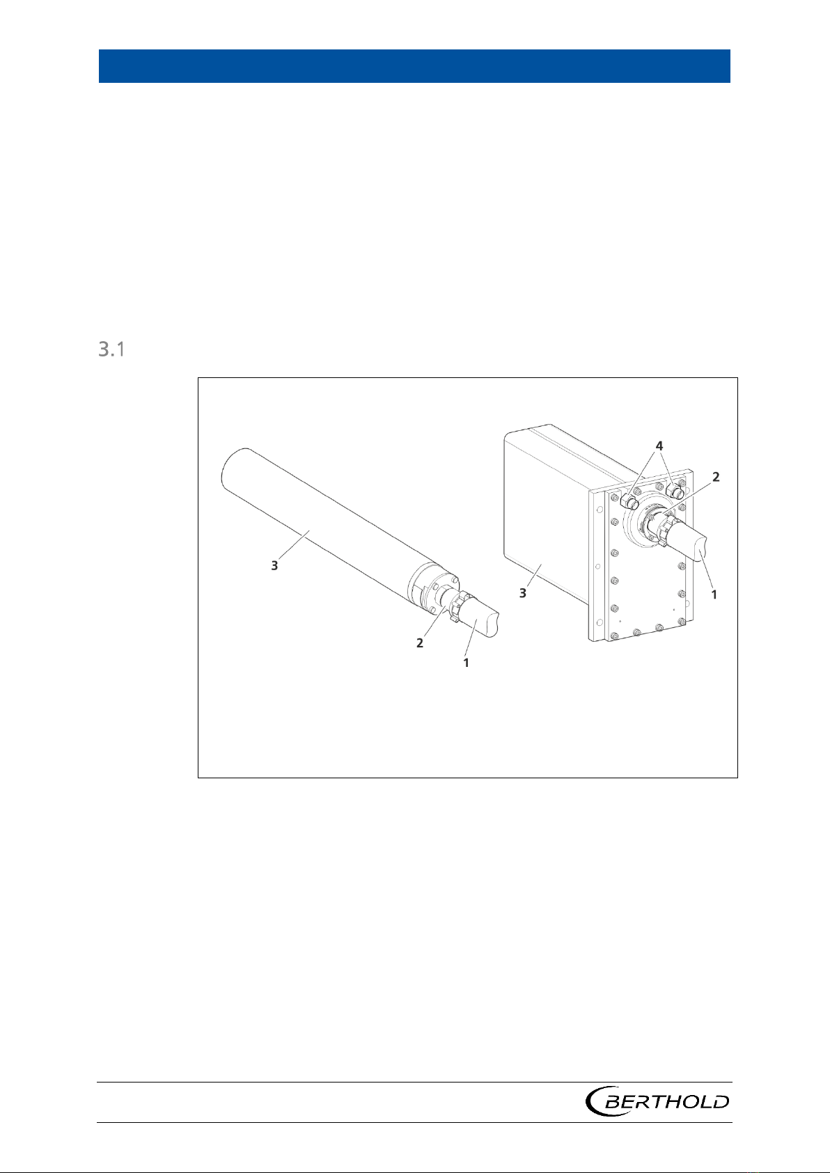
Overview
1
2
3
4
Heat protection hose
PlugProtect plug-in connection
Stainless steel housing
Connections for the water cooling
Fig.1 View of the GAMMAcast detectors,
Left: LB 6739 / LB 6760; Right: LB 6752
The GAMMAcast detectors consist of the following components:
•Stainless steel housing
•Electronics with integrated CPU
•Scintillator (crystal - LB 6739 / LB 6760 or PVT - LB 6752)
•Water cooling system (optional for LB 6739 / LB 6760)
•Connection cable with heat protection hose and PlugProtect plug-in connec-
tion.

3 Product Description
GAMMAcast Detectors
48452BA2 Rev.06, 04/2023
9
3.1.1 Scintillator
The GAMMAcast detectors are distinguished by means of the external dimensions
and the scintillators used.
•GAMMAcast detector LB 6739:
Scintillation counter with crystal and photomultiplier (see technical infor-
mation, chapter 1)
•GAMMAcast detector LB 6752:
Polymer scintillation counter with photomultiplier (see technical information,
chapter 1)
•GAMMAcast detector LB 6760:
Scintillation counter with crystal and silicon photomultiplier (see technical in-
formation, chapter 2)
3.1.2 Connection Cable
The plug-in connection "PlugProtect" protects the transition between the GAM-
MAcast detector and the connection cable against moisture penetration. The heat
protection hose covering the connection cable protects it against too high temper-
atures.
The connection cables are commonly connected to a terminal box. For this purpose,
a variant with HeavyCon plug or open ends can be used. The terminal box is con-
nected to the EVU.
3.1.3 Water Cooling System
A version of the GAMMAcast detectors with water cooling is available to protect
the scintillators against too high temperatures. The GAMMAcast detector LB 6752
has already been provided with a water cooling system integrated into the hous-
ing.
Storage
Keep devices in a dry (no condensation), dark (no direct sunlight), clean and lock-
able room. Stay within the temperature range for storage (see document “Tech-
nical Information”).

GAMMAcast Detectors
4 Commissioning
10
48452BA2 Rev.06, 04/2023
4Commissioning
Initial Operation
DANGER
Danger to life from electric shock!
Installation may only be carried out by a qualified electrician.
Installation may only be carried out if all components has been de-ener-
gised.
Only open the housings when there is no voltage.
NOTICE
Danger due to inadmissible place of use!
The GAMMAcast detectors must not be used in systems in which explosive
gases or vapours may form. They are not explosion-proof.
NOTICE
Risk of breaking!
The GAMMAcast detector contains a PMT with glass housing and/or a fragile
scintillation crystal. The glass housing of the PMT can break. The crystal can
break or splinter.
Handle the GAMMAcast detector with care.
Mount the GAMMAcast detector to the outside or inside of the mould. If required,
connect the water cooling system. Additional information is provided in chap. 4.3.
The GAMMAcast detector is connected either via a terminal box (Fig.3) or directly
to the EVU. The connection diagram of the respective evaluation unit is to be taken
into account. For the connection to the EVU, please also refer to the connection
diagram provided in the operating manual of the EVU.

4 Commissioning
GAMMAcast Detectors
48452BA2 Rev.06, 04/2023
11
Terminal Box
The detectors and the EVU are to be connected via the terminal box. This connec-
tion is to be made with a standard 6–wire shielded cable (6 x 0.5 mm²) with a max-
imum length of up to 1000 m. As required, the terminal box can be ordered for
open ends (Mat. No. 07005, Fig.2, item 1) or with an industrial connector (Mat.
No. 34787, Fig.2, item 2).
1 Terminal box for open ends
2 Terminal box for industrial connector
Fig.2 Terminal box for detectors
4.2.1 Mounting the Terminal Box
Fig.3 Mounting the terminal box (variant with industrial connector)
Install the terminal box near the mould in a protected but easily accessible place.
The terminal box can be installed in different ways and manners depending on:
•the general physical conditions at the site.
•the temperature conditions around the casting floor.
•the distance from the mold.
The terminal box must be secured to a wall or to a pillar so that the sturdy cable
(connection lines inside the hose) will not move the terminal box.

GAMMAcast Detectors
4 Commissioning
12
48452BA2 Rev.06, 04/2023
4.2.2 Connect Terminal Box
1
2
3
4
Cover
Connector socket
Connection cable
Terminal strip
Fig.4 Connect terminal box (variant with industrial connector)
Cables coming from the GAM-
MAcast detector
Terminal strip of the EVU or of the termi-
nal box
Yellow
1
Black
2
White
3
Brown
4
Red
5
Gray1
61
Violett
7
1If connecting to the EVU LB 452 castXpert grey may also be connected to pin 6, please also refer
to the connection diagram in the technical information of the EVU LB 452.

4 Commissioning
GAMMAcast Detectors
48452BA2 Rev.06, 04/2023
13
Water Cooling System Connection
The GAMMAcast detector LB 6752 is already provided with a water cooling system
upon delivery. The GAMMAcast detectors LB 6739 and LB 6760 can be purchased
with an optional water cooling system.
NOTICE
Please make sure that the water is drained at the highest point, as shown in
(Fig.5, item 3 and Fig.6, item 4).
1
2
3
4
Water cooling inlet
Plug-in connection "PlugProtect"
Water cooling outlet
Water cooling system
Fig.5 GAMMAcast detector LB 6739 or LB 6760 with water cooling system

GAMMAcast Detectors
4 Commissioning
14
48452BA2 Rev.06, 04/2023
1
2
3
4
Connection cable with heat protection hose
Plug-in connection "PlugProtect"
Water cooling inlet
Water cooling outlet
Fig.6 GAMMAcast detector LB 6752 with integrated water cooling system
Insert the GAMMAcast detector with water cooling system into the bore in the
mould that corresponds to the GAMMAcast detector. When using a water cooling
system (with GAMMAcast detector LB 6739 or LB 6760), please note that the bore
must be accordingly bigger.
When fixing the GAMMAcast detector to the water cooling system, please make
sure that the discharge nozzle on the mould is at the highest point (Fig.5, item 3
and Fig.6, item 4.) This will ensure that there is always enough water in the water
cooling system and that no air bubbles can form.
NOTICE
Damage to the device!
When using water that does not have the same quality as drinking water, the
water cooling system and the GAMMAcast detector may be damaged due to
deposits of dirt particles.
Reduced cooling power!
Only water that has the same purity as drinking water may be used as coolant.
Please observe the minimum cooling water requirement of the GAMMAcast
detectors (chap. 4.4).
Connect the inlet and outlet of the cooling water to the GAMMAcast detector
(LB 6739 / LB 6760: Fig.5, item 1 and 3; LB 6752: Fig.6, item 3 and 4).
This manual suits for next models
2
Table of contents
Other Berthold Security Sensor manuals

Popular Security Sensor manuals by other brands

pdlux
pdlux PD-MV1012-A instructions

Bosch
Bosch DS935 VdS installation instructions

STEINEL
STEINEL professional HPD2 KNX quick start guide

Takex
Takex Quad PB-IN-50HF installation manual

Herth+Buss
Herth+Buss ELPARTS SelectH2 mini operating instructions

ThermoFisher Scientific
ThermoFisher Scientific Vanquish VH-D10 operating manual


iRay Technology
iRay Technology Mars1717V user manual

Erone
Erone SEF2410AV Installation Notice

PCB Piezotronics
PCB Piezotronics TORKDISC 5302D-01A/012AC080AT Installation and operating manual

optrel
optrel weldCap quick start guide

Afriso EURO-INDEX
Afriso EURO-INDEX LAG-14 ER operating instructions

ZooZ
ZooZ ZSE42 800LR user manual