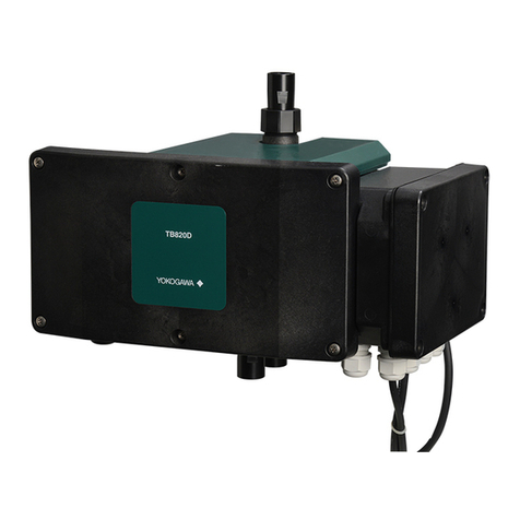
YOKOGAWA TB820D User manual

Technical
Information
FLEXA, FLXA and SENCOM are trademarks or registered trademarks of Yokogawa Electric Corporation.
All other company and product names mentioned in this user’s manual are trademarks or registered trademarks of their respective companies.
We do not use TM or ® mark to indicate those trademarks or registered trademarks in this user’s manual.
TB820D, TB830D
Sampling System Selection
Manual
TI 12E01B30-01EN
TI 12E01B30-01EN
©Copyright Oct. 2022
3rd Edition Mar. 2023
CONTENTS
Introduction .............................................................................................................2
1 Dimensions ...................................................................................................3
1.1 TB820D Dimensions ............................................................................................ 3
1.2 TB830D Dimensions ............................................................................................ 6
2.
Installation .................................................................................................... 16
3. Piping.......................................................................................................... 17
3.1 TB820D (-NN, -A5) Piping .................................................................................. 17
3.1.1 Head tank and Piping Parts ................................................................ 27
3.1.2 System without a Head Tank .............................................................. 31
3.2 TB830D (-NN, -A5) Piping .................................................................................. 32
3.2.1 Piping type .......................................................................................... 33
3.2.2 Head tank............................................................................................ 34
4. Wiring.......................................................................................................... 35
4.1 TB820D wiring .................................................................................................... 35
4.1.1 SENCOM cable for turbidity and chlorine (A) ..................................... 39
4.1.2 Power cable for FLXA402T (B)........................................................... 39
4.1.3 Power supply cable (C)....................................................................... 39
4.1.4 Wiring with PG400 .............................................................................. 40
4.1.5 When Relay box for solenoid valve is included .................................. 40
4.2 TB830D Wiring.................................................................................................... 44
4.2.1 SENCOM cable for Turbidity/Chlorine (A) .......................................... 47
4.2.2 FLXA402T power supply cable (B)..................................................... 47
4.2.3
TB830D power supply cable (C), Relay box power supply cable (D)
........... 47
4.2.4 Power supply cable (E) ....................................................................... 47
4.2.5
Without a sampling system and with a Relay box for solenoid valve
............ 51
5 Zero Turbidity Filter................................................................................... 54
6 Operation.................................................................................................... 55
6.1 TB820D Supplying a Sample and Adjusting the Flow Rate .......................... 55
6.2 TB830D Preparation for Operation .................................................................. 56
7. Automatic cleaning/Automatic zero calibration Sequence.................. 58
7.1 TB820D Sequence ............................................................................................. 58
7.2 TB830D Sequence ............................................................................................. 60
Revision Information ........................................................................................... 62

2
TI 12E01B30-01EN
TB820D and TB830D Sampling System Selection Manual
Introduction
This manual describes how to select a sampling system when the analyzer combined with the
“TB820D Right Angle Scattered Light Turbidity Detector” and “TB830D Surface Scattering Light
Turbidity Detector” does not have an assemble stanchion.
If you specify without a sampling device (Sux code -NN, -A5), you have to select and build
system components such as a head tank, solenoid valve, and manual valve. This document
describes how to select the solenoid valves and head tanks necessary for conguring a sampling
system, as well as piping and wiring diagrams.
Media No. TI 12E01B30-01EN 3rd Edition : Mar. 2023 (YK)
All Rights Reserved Copyright © 2022, Yokogawa Electric Corporation

TB820D and TB830D Sampling System Selection Manual 3
TI 12E01B30-01EN
1 Dimensions
1.1 TB820D Dimensions
Top cover
Detection unit Flow cell
Smart unit
Smart unit cover
Front cover
sample outlet
LED
sample inletDrain
Fuse
Figure 1 TB820D part name
Nov.22,2012-00

TB820D and TB830D Sampling System Selection Manual 4
TI 12E01B30-01EN
sample outlet
Rc1/2 or 1/2NPT
Ultrasonic oscillator
(for oscillator) wiring port
Cleaning controller
sample inlet
Rc1/2 or 1/2NPT
Drain
Rc1/2 or 1/2NPT
For wall mounting
(4-M5 screws)
87
368
45
56
174
200
500
or more
500
or more
Maintenance space
200
or more
250
or more
(368) (261)
(275)
261
Unit: mm
54 100
100
2-R3
2-R3
160
Figure 2 TB820D Dimensions
Nov.22,2012-00

TB820D and TB830D Sampling System Selection Manual 5
TI 12E01B30-01EN
nInstallation Dimensions
Install the TB820D’s detector unit in pipes or walls using their special mounting brackets,
respectively. Note that these mounting brackets are supplied only when specied.
lPipe Mounting (Option Code “/U”)
For information on the converter, read FLXA402T IM.
54 141
128 Unit: mm
Mounting 2-inch pipe
(ø60.5)
Figure 3 Diagram of TB820D Pipe Mounting
lWall Mounting (Install the detector with four M5 screws)
For information on the converter, read FLXA402T IM.
100
2-R3
2-R3
160
Unit: mm
Figure 4 Diagram of TB820D Wall Mounting
nConduit adaptor (/CB3, /CD3, /CF3)
G1/2 (/CB3), 1/2NPT (/CD3), M20x1.5 (/CF3)
Adapter
45
(1.77)
Approx.55
(2.17)
Cable gland
for adapter
Case Unit: mm
(inch)
Figure 5 Diagram of TB820D conduit adopter

TB820D and TB830D Sampling System Selection Manual 6
TI 12E01B30-01EN
1.2 TB830D Dimensions
●Without sampling system (-NN, -A5) Unit: mm
246
208
142
296
50
38
14.5
100
56
(22) 150
4-ø4.2 hole
4-ø6.2 hole
Figure 6 TB830D-NN, -A5 Dimensions
lMaintenance space
250 or more
250 or more
Unit: mm
500 or more
250 or more
Maintenance space
Maintenance space
Maintenance space
Maintenance space
Figure 7 TB830D maintenance space

TB820D and TB830D Sampling System Selection Manual 7
TI 12E01B30-01EN
lPipe mounting hardware (/U) for -NN, -A5 Without sampling system Unit: mm
208 (140)
(215)
150
(22)
56
70
100
38 35
157
203
4-ø10
4-M5
Panel mounting
hardware: /U
Pipe 50A
(or 2B)
U-Bolt
Approx. 372
Figure 8 Pipe mounting hardware (/U) for -NN, -A5
lRack or wall mounting hardware (/R) for -NN, -A5 Without sampling system Unit: mm
166 25(22)
56
190
220
38
105
125
3-ø6.2
ø10
4-M5 18
Approx. 295
Rack or wall mounting
hardware: /R
Figure 9 Rack or wall mounting hardware (/R) for -NN, -A5

TB820D and TB830D Sampling System Selection Manual 8
TI 12E01B30-01EN
nOther Dimensions
lTerminal box A Unit: mm
Terminal box A is supplied when “/ARS” option code is specied.
Terminal box A can be connected to the pipe when “/C□” option code is specied.
275
203
9211
(12)
70
75
17
Figure 10 Terminal box A dimensions
lInstallation of pipe mounting hardware (/U) on the terminal box A
275
203
(24)
(52)
92 1070
(22)
70
100
75 35
142
200
60
17
277
2-ø9
4-M5
Panel mounting
hardware: /U Panel mounting
hardware: /U
Pipe 50A
(or 2B)
U-Bolt
Figure 11 Installation of pipe mounting hardware (/U) on the terminal box A
lInstallation of rack or wall mounting hardware (/R) on the terminal box A
4-ø6.5
275
203
30
92
11
70
110
130
75 10
130
160
17
235
4-M5
Panel mounting
hardware: /R
Figure 12 Installation of rack or wall mounting hardware (/R) on the terminal box A

TB820D and TB830D Sampling System Selection Manual 9
TI 12E01B30-01EN
lTerminal box B Unit: mm
Terminal box B is supplied with the product in the following cases.
• When both Sampling system “-NN” and Option “/C□” (Conduit adapter) are specied, but “/
ARS” (with Arrester) is not specied.
• When Sampling system “-A1” is specied but “/ARS” (with Arrester) is not specied.
• When Sampling system “-A2” or “-A3” is specied and Option “/PH□2” or “/PH□7” or “/FC” is
specied, but “/ARS” (with Arrester) is not specied.
Terminal box B can be conduit wired.
132 66
(31)
144
(31)
114.1
23.3
2-M4
Figure 13 Terminal box B Dimensions
lInstallation of pipe mounting hardware (/U) on the terminal box B
96
27
90 15
100
114
140
56
4 66 (59)
132.5
(28)
2-ø9
2-M4
143.5
216.5
60
73
Panel mounting
hardware: /U
Panel mounting
hardware: /U
Pipe 50A
(or 2B)
U-Bolt
Figure 14 Installation of pipe mounting hardware (/U) on the terminal box B

TB820D and TB830D Sampling System Selection Manual 10
TI 12E01B30-01EN
lInstallation of rack or wall mounting hardware (/R) on the terminal box B Unit: mm
132.5
143.5
4 66
20
216.5
70
60
27
90
90
114
140
2-ø10 2-ø5.5
2-M4
20
30
73
Panel mounting
hardware: /R
Figure 15 Installation of rack or wall mounting hardware (/R) on the terminal box B
lRelay box
A relay box is supplied with the product when “-A2”, “-A3”, or “-A5” is specied. A relay box is
used to drive the solenoid valve for automatic cleaning/automatic zero calibration. Select /C□
(conduit adapter) to provide conduit wiring to the relay box.
165
165
168.5
158.5
40
80
80 4-M6
Figure 16 Relay box Dimensions

TB820D and TB830D Sampling System Selection Manual 11
TI 12E01B30-01EN
lInstallation of pipe mounting hardware (/U) on the relay box Unit: mm
165
165
(22)
(52)
168
70
80
100
80 8
200
60
50
235
2-ø9
4-M6
Panel mounting
hardware: /U Panel mounting
hardware: /U
Pipe 50A
(or 2B)
U-Bolt
Figure 17 Installation of pipe mounting hardware (/U) on the relay box
lInstallation of rack or wall mounting hardware (/R) on the relay box
165
165
4-ø10
13
168
70
80
100
80 8
200
15 35
235
4-M6
Panel mounting
hardware: /R
Figure 18 Installation of rack or wall mounting hardware (/R) on the relay box
lConduit adaptor (/CB, /CD, /CF)
G1/2 (/CB), 1/2NPT (/CD), M20x1.5 (/CF)
Adapter
45
(1.77)
Approx.55
(2.17)
Cable gland
for adapter
Case Unit: mm
(inch)
Figure 19 Diagram of TB830D Conduit adaptor (/CB, /CD, /CF)

TB820D and TB830D Sampling System Selection Manual 12
TI 12E01B30-01EN
lPG400 dimensions and Mounting
PG400 will be attached if you choose TB820D-U1.
165
137
80
165
146 9
80
137
4-M6 depth 8
(not used)
For Oscillator cable
For power supply
Unit: mm
40
Figure 20 Diagram of PG400
● PG400conduitAdapter(Optioncode:/CB,/CD,/CF)
45 Adapter
Cable gland for adapter
G1/2 female thread (/CB)
1/2 NPT female thread (/CD)
M20x1.5 (/CF)
Unit: mm
Plate
Case
Figure 21 Diagram of PG400 conduit adapter

TB820D and TB830D Sampling System Selection Manual 13
TI 12E01B30-01EN
(Note)The universal mounting kit (/UM) contains the pipe and wall mounting hardware (/U) and the panel
mounting hardware (/PM).
● PG400panel mounting hardware (Option code: /PM, /UM)
2-M5 length 35
185
178
100
195
121
Panel thickness
1 to 12
Spacing panel cutout
4-M6 *
138
+1
0
138
+1
0
Unit: mm
*: Tighten the four screws to a torque of 2 N•m.
Figure 22 PG400 panel mounting hardware (/PM, /UM)
● Panelmountinghardwareforreplace(fromPUS400G/TUS400G)(Optioncode:/PM1)
180
180
138
138
173 +1.1
0
156+1.1
0
121
121
Unit: mm
Panel cutout dimensions
Part for
replacement
Figure 23 PG400 panel mounting hardware for replace from PUS400G/TUS400G (/PM1)

TB820D and TB830D Sampling System Selection Manual 14
TI 12E01B30-01EN
Note: The wall on which the analyzer is mounted should be strong enough to bear the weight of
more than 8 kg.
● PG400wall mounting hardware (Option code: /U, /UM)
165 168
13
100
70
165
234.5
200
50
15
For wall mounting
3-ø10 holes
4-M6 * Unit: mm
*: Tighten the four screws to a torque of 2 N•m.
Figure 24 PG400 wall mounting hardware (/U, /UM)
● PG400wall mounting hardware (for replacement from PUS400G/TUS400G) (Option code: /U1)
100
70
185
42
15
4-M6 * Unit: mm
For wall mounting
3-ø10 holes
*: Tighten the four screws to a torque of 2 N•m.
Figure 25 PG400 wall mounting hardware for replacement from PUS400G/TUS400G (/U1)

TB820D and TB830D Sampling System Selection Manual 15
TI 12E01B30-01EN
Note: The wall on which the analyzer is mounted should be strong enough to bear the weight of
more than 8 kg.
● PG400 pipe mounting hardware (Option code: /U, /UM)
155
100
200
50 184.5
165
(209)
Pipe mounting (Horizontal) Pipe mounting (Vertical)
Pipe 50A
(ø60.5)
M8 U-bolt
4-M6 *
Unit: mm
*: Tighten the four screws to a torque of 2 N•m.
Figure 26 PG400 pipe mounting hardware (/U, /UM)
●PG400 stainless steel hood (Option code: /H6, /H7)
184
220
(70)
(100)
9
165
165
72
57
(50)
199
Unit: mm
Figure 27 PG400 stainless steel hood (/H6, H7)

TB820D and TB830D Sampling System Selection Manual 16
TI 12E01B30-01EN
2.
Installation
The TB820 and TB830D should be installed in a location:
• In a building or a cabinet where no direct sunlight or rainwater can get inside.
Direct sunlight may cause an abnormal rise in the temperature inside the instrument and
discoloration or deterioration of resin parts. Also, removing the cover for maintenance during
rain may damage the electrical parts inside the instrument.
Install the instrument in a building or cabinet away from direct sunlight and rainwater.
• With little vibration
Vibration may result in incomplete connections such as external wiring.
• Where corrosive gases are not present.
Corrosive gas can damage electrical component inside the instrument.
• Where humidity of 0 to 90% RH is maintained (No condensation)
No installing in a place with high humidity.
• With little temperature change, close to normal temperature
The ambient temperature must not exceed the range of -5 to 55°C.
If the temperature of the sample is lower than the ambient temperature, it may cause
condensation.
Take protective measures to prevent a sample and the tap water from freezing, if necessary.
• With adequate maintenance space and easy access for maintenance work.
Secure sucient maintenance space for maintenance such as replacement, cleaning, and
calibration.
• Where the drain is provided
The sample needs to be drained during cleaning and calibration, so install it in a place
where drainage is possible.
• Near the place where the converter is installed
Consider the length of the connection cable to the converter when installing.

TB820D and TB830D Sampling System Selection Manual 17
TI 12E01B30-01EN
3. Piping
3.1 TB820D (-NN, -A5) Piping
See Section “3.1.1 Head tank and Piping Parts” for head tank types and selection.
nPressurized head tank (/D1)
● Manualcleaning,manualzerocalibration
In a system using an open head tank, air bubbles may form from air dissolved in a sample under
the reduced pressure in piping and enter into the detector, resulting in an incorrect measurement.
For low turbid waters where the eect of air bubbles is a concern, install a pressurized head
tank to prevent pressure changes in the piping from the head tank to the detector outlet and thus
prevent air bubbles from occurring in the pipe.
Note: Needle valves are required to adjust the small ow rate by changing the valve opening.
Sample
Tap water
Drain
<PIPE>
DG1: Pressurized head tank for low turbidity
F1: Zero turbidity filter 1 μm
F2: Zero turbidity filter 0.2 μm
BV1, 2, 4, 9, 10:
Ball valve
PR1: Pressure regulator
NV1, 2, 3: Needle valve
P1: Pressure gauge
ø8/ø6 Polyethylene tube
ø12/ø9 Polyethylene tube
ø22/ø15 Flexible mesh-reinforced tube
ø26/ø19 Flexible mesh-reinforced tube
ø33/ø25 Flexible mesh-reinforced tube
BV9
BV10
PR1
NV1
BV2
BV7
F2F1
NV2
P1
BV1
DG1 TB820D
NV3
BV4
F2: Use 0.2 μm or 1 μm lter. However, if the sample is more than 2 NTU, only the 1 μm lter may be used.
BV2: Supply Zero water to the detector by operating the ball valve
BV4: Drain dirt and sediment by opening the drain ball valve
NV3: Valve for Flow rate adjustment. Be sure to place it after the detector exit
NV1: Keep a very small amount of water owing at all times to prevent contamination of the zero lter and prevent freezing in
winter.
Atmospheric air open on the outlet side of NV3
Figure 28 Piping diagram for TB820D /D1 without Automatic clean/ Without Automatic zero
calibration

TB820D and TB830D Sampling System Selection Manual 18
TI 12E01B30-01EN
●Automatic cleaning, automatic zero calibration
Note: Needle valves are required to adjust the small ow rate by changing the valve opening.
SV1
SV2
Check valve
SV4
Sample
Tap water
Drain
<PIPE>
DG1: Pressurized head tank for low turbidity
F1: Zero turbidity filter 1 μm
F2: Zero turbidity filter 0.2 μm
BV4, 9, 10:
Ball valve
SV1, 2, 3 Solenoid valve
PR1: Pressure regulator
NV1, 2, 3: Needle valve
P1: Pressure gauge
ø8/ø6 Polyethylene tube
ø12/ø9 Polyethylene tube
ø22/ø15 Flexible mesh-reinforced tube
ø26/ø19 Flexible mesh-reinforced tube
ø33/ø25 Flexible mesh-reinforced tube
BV9
BV10
PR1
NV1
BV7
F2F1
NV2
P1
DG1 TB820D
NV3
BV4
Solenoid valve is installed and set in the cleaning / calibration controller (Relay box)
Atmospheric air open on the outlet side of NV3
F2: Use 0.2 μm or 1 μm lter. However, if the sample is more than 2 NTU, only the 1 μm lter may be used.
NV3: Valve for Flow rate adjustment. Be sure to place it after the detector exit
NV1: Keep a very small amount of water owing at all times to prevent contamination of the zero lter and prevent freezing in
winter.
Figure 29 Piping diagram for TB820D /D1 with Automatic cleaning/ With Automatic zero
calibration
(1) Piping of the Sample Line to the Detector
This piping is for introducing a sample into the measurement cell of the detector. Install a
pressurized head tank (for low turbidity), valves and pipes by referring to the diagram in Figure 28
and Figure 29.
1. For the piping from a sampling point to a sample valve, use a hose/tube with sucient
diameter that provides adequate ow of sample in order to prevent clogging. The hose/tube
also should withstand the sample pressure. The specied sample pressure when using a
pressurized head tank is in the range of 20 to 500 kPa. One example is a rigid PVC tube
with nominal size of 16 (22 mm OD).
2. For the piping between the valve and the pressurized head tank, use a 8 mm OD x 6 mm ID
polyethylene tube and the corresponding tting.
3. To the sample inlet of the detector, attach a 3-way (tee) or appropriate tting corresponding
to the inlet’s connection size (Rc1/2 or 1/2 NPT). This allows switching of the sample ow
and the zero water ow.

TB820D and TB830D Sampling System Selection Manual 19
TI 12E01B30-01EN
4. For the piping between the pressurized head tank and the detector, connect a valve to one
end of the 3-way tee tting and connect a 8 mm OD x 6 mm ID polyethylene tube and the
corresponding tting between the valve and the pressurized head tank.
5. To the tting on the bypass valve (needle valve) at the top of the pressurized head tank,
connect a 8 mm OD x 6 mm ID polyethylene tube.
6. To prevent clogging or stagnation of air bubbles in the pipe line, install the pipes so that no
bends or stagnation occurs.
(2) Piping of the Sample Line from the Detector
This piping is for draining a sample from the measurement cell of the detector during
measurement. As shown in the piping diagram in Figure 28 and Figure 29, connect a needle
valve to the sample outlet of the detector. By adjusting the opening of this valve and the bypass
valve (needle valve) at the top of the pressurized head tank, the pressure change is controlled in
the piping between the head tank and the detector outlet, and thus the generation of air bubbles
is prevented.
1. To the sample outlet of the detector, connect a tting, such as an elbow tting,
corresponding to the connection size (Rc1/2 or 1/2 NPT female) and a needle valve.
2. To the outlet of the needle valve, connect a 8 mm OD x 6 mm ID polyethylene tube using the
corresponding tting to drain the sample to a drain pipe.
3. As shown in Figure 28 and Figure 29, the sample from the detector should be discharged to
the atmosphere at a point higher than the measurement cell of the detector. If not, a siphon
may be created and the measurement cell may not be lled with a sample. In addition, if the
sample inow stops, the sample will be drawn o and the measurement cell will be emptied,
which can cause damage to the Pulse Generator for Clean Unit, if used.
(3) Drain Piping
This piping is for draining a sample from the measurement cell of the detector and a head tank
during cleaning, calibration, or other maintenance.
1. The drain of the detector is Rc1/2 (or 1/2 NPT female) thread. Install a tting corresponding
to the thread and connect a hose/tube with sucient diameter that provides adequate ow
of sample, to route the sample from the detector to a drain pipe. Install the pipe so that no
stagnation occurs.
2. As shown in Figure 28 and Figure 29, install pipe so that the sample can be drained from the
head tank to the drain pipe.
(4) Piping of the Zero Water Line
This piping is for introducing tap water to a zero turbidity lter and then to the detector for zero
calibration or measurement cell cleaning.
1. As shown in Figure 28 and Figure 29, install a tap water valve and a zero water drain valve.
2. Connect a zero water supply valve to one end of the 3-waytee tting attached to the sample
inlet of the detector.
3. Install a tting corresponding to the piping connection of the zero turbidity lter and connect
an hose/tube that can withstand the pressure of tap water, such as a rigid PVC tube. The
ow rate of zero water supply should be in the range of 1 to 3 L/min.
4. For the specications of the zero turbidity lter, see GS 12E01B30-01EN
5. To prevent corrosion of water inside the zero turbidity lter, allow water to ow through
the lter and ow out from the zero water drain valve continuously at a ow rate of
approximately 10 mL/min.

TB820D and TB830D Sampling System Selection Manual 20
TI 12E01B30-01EN
nSimple head tank (/D2)
●Manual cleaning, manual zero calibration
An optional simple head tank with a vent to the atmosphere (option code “/D2”), shown in Figure
38, is available from Yokogawa. The piping diagram of the simple head tank is shown in Figure
30, Figure 31 and Figure 32. The installation of the piping for the simple head tank is described
below.
Note: Needle valves are required to adjust the small ow rate by changing the valve opening.
HT
Sample
Tap water
Drain
<PIPE>
HT: Simple head tank
F1: Zero turbidity filter 1μm
BV1, 2, 4, 5, 7, 9, 10:
Ball valve
PR1: Pressure regulator
NV1: Needle valve
ø8/ø6 Polyethylene tube
ø12/ø9 Polyethylene tube
ø22/ø15 Flexible mesh-reinforced tube
ø26/ø19 Flexible mesh-reinforced tube
ø33/ø25 Flexible mesh-reinforced tube
BV9
BV10
PR1
BV2
NV1
F1
BV7
BV1
TB820D
BV5
BV4
Atmospheric air open on the outlet side of Needle valve
Needle valve Valve for Flow rate adjustment. Be sure to place it after the detector exit
Ball or Needle valve:without cleaning / calibration or Solenoid valve: with cleaning / calibration
Needle valve: Keep a very small amount of water owing at all times to prevent contamination of the zero lter and
prevent freezing in winter.
Figure 30 Piping diagram for TB820D /D2 without automatic cleaning / without automatic zero
calibration
Other manuals for TB820D
2
This manual suits for next models
1
Table of contents
Other YOKOGAWA Security Sensor manuals