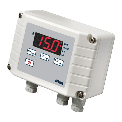
Proxel DTSF3+ User manual

Proxel Engineering Ltd ------------------------www.proxel-bg.com----------------- -DTSF3+ v2.4 /2 17
„DTSF3+” Temperature Controller For Solar Thermal And Heating
Application With 8 Schemes
B IEF DESC IPTION
The unit is a programmable digital temperatute controller for solar thermal and
heating plants. It manages the interaction between the solar collector, hot water tank,
storage tank, boiler, pumps, valves and electric heater. The unit helps to improve
thermal comfort by combining high efficiency with autonomy of the system. The
joint functional work of differential temperature, built-in clock and a flexible treshold temperatures
further helps to increase energy savings. It has 8 pre-programmed functional diagrams which cover
vast range of prooved by practice application. The application of the device extends from thermo-
syphonic solar water heaters to more complex solar systems with a combination of hot water tank
and storage tank, boiler and heating. It also can control one HF pump with PWM input.
Functional diagrams, schemes, sensors and outputs arrangement:
1
Scheme 0 – Thermosyphonic panel with integrated tank and trace heating
Sensors
Schm=0; “TSyphTrH”
• TS1 – trace temperature
• TS2 – solar tank temperature
• TS3 – not used;
• Level sensor - Terminals 3 and 4
Outputs
• R1 – trace heater
• R2 – electric heater of solar operated tank
•
R3 – refill valve (N.C.)
Level sensor: Controls electric valve for proper boiler fill up while monitoring the water level with submerged
electrode.
2
Scheme 1- Thermosyphonic panel with integrated tank and recirculation;
Sensors
Schm=1; “TSyph eC”
• TS1 – temperature of suplimentary tank/recirculation point
• TS2 – solar tank temperature
• TS3 – trace temperature
Outputs
• R1 – recirculation pump
• R2 – electric heater of solar operated tank
• R3 – * valve – not used
3
Scheme 2- Solar panel with one storage tank and electric heater (standard)
Sensors
Schm=2; „dT.EL+T1”
• TS1 – temperature of solar panel
• TS2 – tank temperature at bottom (at coil position)
• TS3 – tank temperature at top (for heater control)
Outputs
• R1 – solar pump
• R2 – electric heater of tank
• R3 – emergency draining valve
4
Scheme 2а - Solar panel with two storage tanks – Ta-with electric heater, Tb-with solar heating,
Sensors
Schm=2; „dT.EL+T1”
• TS1 – temperature of solar panel
• TS2 – temperature of electric heater operated tank
• TS3 – temperature of solar operated tank
Outputs
• R1 – solar pump
• R2 – electric heater of tank
• R3 – emergency draining valve
2
5
Scheme 3 - Solar panel with two storage tanks – main and suplimentary with priority
Sensors
Schm=3;“dTETa/Tb”
• TS1 – temperature of solar panel
• TS2 – temperature of tank („A”) - main
• TS3 – temperature of tank („B”) -suplimentary
Outputs
• R1 – solar pump
• R2 – electric heater of tank („A”)
• R3 – 3-way valve main/suplimentary tank
6
Scheme 3а - Solar panel with one tank with two solar coils and electric heater
Sensors
Schm=3;“dTETa/Tb”
• TS1 – temperature of solar panel
• TS2 – temperature of tank – top („A”)
• TS3 – temperature of tank – bottom („B”)
Outputs
• R1 – solar pump
• R2 – electric heater of tank
• R3 – 3-way valve top/bottom
7
Scheme 4 - Solar panel with one tank with two coils, electric heater and suplimentary heater
Sensors
Schm=4; “1B+2C+EL”
• TS1 – temperature of solar panel
• TS2 – tank temperature
• TS3 – suplimentary heating source temperature
Outputs
• R1 – solar pump
• R2 – electric heater of tank
• R3 – DHW suplimentary heating valve/pump
8
Scheme 5 - Solar panel with one tank with two coils, suplimentary heater and heating pump
Sensors
Schm=5; “SolDhwCh”
• TS1 – temperature of solar panel
• TS2 – tank temperature
• TS3 – suplimentary heating source temperature
Outputs
• R1 – solar pump
• R2 – circulation pump for domestic heating
• R3 – DHW suplimentary heating valve/pump
9 Scheme 6 – Solar/supplementary heater with two tanks and two pumps, no priority
Sensors
Schm=6; “SOL+2P2T”
• TS1 – temperature of heat source
• TS2 – temperature of tank – “A”
• TS3 – temperature of tank – “B”
Outputs
• R1 – pump for tank “А“
• R2 – electric heater of tank “А”
• R3 – pump for tank “B”
1 Scheme 7 – Unpreasurized solar panel (open to air system) with el. heater and refill function
Sensors
Schm=7; “dT.EL.T1+ ”
• TS1 – temperature of solar panel
• TS2 – temperature of solar tank
• TS3 – not used
• Level sensor - Terminals 3 and 4; reads level of liquid
Outputs
• R1 – solar pump
• R2 – electric heater of tank
• R3 – refill valve (N.C.)
Level sensor: Controls electric valve for proper solar panel fill up while monitoring the water level with
submerged electrode.

3
TABLE OF AVAILABLE PARAMETERS:
Shceme participation:
Name
Range
Защита
с
Парола
Parameter description
1 2 3 4 5 6 7
1
Clock
h:m:s
Clock
*
*
*
*
*
*
*
2
ОN
24h/15min
Beginning of time zone (El. Heater)
*
*
*
*
*
*
*
3
Off
24h/15min
End of time zone (El. Heater)
*
*
*
*
*
*
*
4
GoodTnk
min÷max
Comfort t
°
°°
°C
in main tank
*
*
*
*
*
*
*
*
5
dT1-Sol
3÷35°C
*
Temperature difference – solar/ tank
*
*
*
*
*
*
*
5а
dT1-hst
2 or 5°C
*
Hysteresis of dT1-Sol
*
*
*
*
*
*
*
6
dT2-Kot
3÷15°C
*
Temperature difference supplementary heater / tank
*
*
*
6а
dT2-hst
2 or 5°C
*
Hysteresis of dT2-Kot
*
*
*
7
MinTank
5÷75°C
*
Minimal tank t
°
°°
°C
maintained by El. heater
*
*
*
*
*
*
*
8
CH Pump
5÷75°C
*
Suplimentary source t
°
°°
°C
to start CH pump
*
9
Ma Tank
1 ÷95°C
*
Maximal t
°
°°
°C
in tank
*
*
*
*
*
*
*
*
1
Min Sol
5÷8 °C
*
Temperature in solar source to enable solar pump
*
*
*
*
*
*
1 а
Min Sol
-hst
2 or 5°C
*
Hysteresis of Min Sol
*
*
*
*
*
*
11
DefrSol
-4 ÷1 °C
*
Defrost t
°
°°
°C
of solar (to starts solar pump)
*
*
*
*
*
*
12
MinKot
5÷9 °C
*
Minimal t
°
°°
°C
of supplementary heating to enable
DHW valve/pump
*
*
*
13
TankA/B
5÷9 °C
*
Tank switching t
°
°°
°C
Main/Storage or (coil 1 / 2)
*
14
PumpSec
2÷128sec
*
Pump operation hold time
*
*
*
*
*
*
15
Act Sol
÷24 min
*
Delay of electric heater activation
*
*
*
*
*
16
AutCool
Y / N
*
Automatic cooling of tank to „GoodTnk” t
°
°°
°c
*
*
*
*
*
*
17
Passwrd
Password for majour parameter access
*
*
*
*
*
*
*
*
18
Schm
÷ 5
*
Application select scheme 0
1
2
3
4
5
6
7
19
Lt./Min
. ÷5.
*
Expected flow of solar pump
(for statistics purpouse)
*
*
*
*
*
*
2
dTLoss
÷1 °C
*
Expected t
°
°°
°C
losses of trace
(for statistics purpouse)
*
*
*
*
*
*
21
Pump%Lo
25÷1 %
*
Minimal opperation speed of HF pump
*
*
*
*
*
*
*
22
PumpºcdT
÷25°C
*
Sets upper t
°
°°
°C
margine obove dT1-Sol for HF
pump to operate at 1 % (speed vs t
°
°°
°c
distributuion)
*
*
*
*
*
*
*
23
SolOvrh
N
*
Solar panel overheating counter
- can be cleared
*
*
*
*
*
*
*
24
TnkOvrh
N
*
Tank overheating counter
- can be cleared
*
*
*
*
*
*
*
*
25
AutoVac
Y / N
*
Automatic activation of “Vacancy” mode
*
*
*
*
*
*
*
*
26
LimTnkА
Y / N
Limiting of Main tank t
°
°°
°C
to “GoodTnk”, excess
energy is transferred to storage tank
*
MEANS FOR PREVENTION AND PROTECTION:
Type Action
1
Anti frost of Solar Forced circulation of solar pump
2
Overheat of solar Forced circulation of solar pump
3
Thermal shock of solar “Slow” solar pump activation
4
Thermal shock of pipeline “Slow” solar pump activation
5
Anti frost of pipeline Trace heating/ Forced circulation of solar pump
6
Tank overheat “Vacancy” mode
Operation with “maximal thermal losses”
Auto cooling to “TBGood”
*Heat transfer to supplementary heating system
*Activation of emergency drainig valve
7
Pumps blockage Forced activation on certain period of inactivity
8
Current time lost (time not being set after power
failure with longer duration)
Blinking display
* Available only for certain operational schemes
4
OTHERS:
„Vacancy” mode - forced cooling of tank (during night time) to have full heat storage for next day.
Selectable hysteresis 2 or 5 ºC Fault notification - entire screen blinking
Displays sensor failure message: „no” – no sensor; “sc” – sensor short circuited
Displays state of R1, R2 and R3 Manual activation/test of pumps
Important parameter change is password protected
Automatical switching to “Vacancy” mode if unit is left unattended and possible tank overheating is sensed
PWM output for HF pump speed control ; PWM – 1kHz
TECHNICAL DATA
Power supply: 23 V±1 % /5 Hz. ≤ 2VА Instalation on DIN rail 35mm; to be incorporated
Enviroment: -5T45, RH8 %
Storage and transportation-2 /+6 º C
Overall dimentions 68x85x58 mm.
Protection casing IP2
Sensors: durability 2 ºC
Measurment and display: -4 ºC÷15 ºC;
Accuracy ±1ºC in range (-5ºC ÷ +1 ºC);
±4ºC not in range
Outputs:
-Relay R1(SPST)- 23 V - 5A or 18 W/AC3 (motor)
-Relay R2(SPDT)- 23 V -16А or 15 W/AC3 (motor)
-Relay R3(SPDT)- 23 V - 5A or 18 W/AC3 (motor
)
Real time clock authonomy up to 2h
MAIN CHA ACTE ISTICS:
1. Supplies directly power for electrical heater (up to3kW) and two circulation pumps / trace heater or
directional valve.
2. Reads three temperatures.
3. Build in conductivity sensor - terminals 3 and 4 – (TS3 not used) for water level monitor and filling
4. Fully programmable by 29 parameters
5. Fast and direct selection of heater operation mode by separate button among „Auto” /On./ Off./Vacancy
6. Build in real time clock with programmable time zone for additional electric heater activation.
7. Relay outputs 3 (separate) for:
- R1 n.o. SPST, supplies phase for pump/trace heating (HFпомпа)
- R2 n.o./n.c SPDT, voltage free contact for electric heater
- R3 n.o./n.c SPDT, supplies phase for pump/direction valves
8. Backup power supply for real time clock
9. Alphanumeric LCD display 8х2 rows.
1 . Navigation – 3 push buttons. One button for elecric heater activation
11. Statistics (solar energy accumulated, alarm events)
12. Diagnostic information for sensor failure.
13. A set of functional means for independatnt action at critical events.
WI ING DIAG AM
Attention!:
Junction for heater’s neutral “N” should be made on external terminal block (not provided)!
All conections to PE should be made to external terminal block (not provided)!
- Power supply 23 V AC – (internal and R1) – #17 (Live “La”); #16 („N”);
- R1: Pump/trace heating – #18 (switches Live); #15 („N”); – 5А max.
- R2: Electric heater – #2 (separate Live ”Lb”); #22 output – 16А max.
- R3: Pump2/Valve(Open/Close) – (switches Live) #13 (n.o); #14 (n.c. ) – 5А max.
Terminals 3 and 4 – level sensor input (measures conductivity of water)
Terminals 1 and 2 – PWM output for HF pumps
Attention!
Power supply should be applied via fuses:
- La – Circuit Breaker max 6А for trm. 17
- Lb - Circuit Breaker max 20А for trm. 20
- If UPS is used, tem. 17/16 should be
supplied by UPS while trm.20 and heater
“N” should be connected before UPS
(directly to mains).

5
S:XX°cAUT
B:YYºcA:ZZ
Instalation and commusioning
This device is dedicated to be incorporated in apartment electrical box with size of 4 or more poles or a cabinet and
can be attached on 35mm DIN rail.
USAGE
Front pannel
Description
- LCD display, alphanumeric type with two rows and back light [5]
- 3x push buttons: [1] for Down „Dn↓”, [2] for Up „Up↑”, to select „Set” [3]
- Push button for selection of operation mode (of heater): [4] „-^v^v-”
- Indicaton of alarm event – blinking of backlight (if a sensor is defective or
current time is lost).
Usage of buttons:
- buttons [1]„Dn-↓”/ [2] „Up- ↑”: navigates among list of parameter screens previous/next;
increase / decrease selected value wih 1;
- button [3] „Set” toggles buttons [1] and [2] usage, to select parameters or change value of selected parameter
-
button [4] „-^v^v-” – selects the operational mode of the unit (heater) AUTO/ ON/ OFF/ VACANCY
Available windows and usage
Window #1 - Main window
Displays temperature reading of sensors and operational mode of outputs.
- ow 1: temperature reading of solar sensor ”XX” / % of HF pump (if password is set),
Operational mode of the unit (electric heater): AUTO/OFF/ON/VAC.
Each one second the mode and state of the R2 output’s state is displayed alternatively
if R2 is switched on (activated) and if R2 is switched off (not active).
Modes:
- “AUTO” – auto mode, El. heater operates according to preset temperature setpoint and selected time zones.
- “OFF” – El. heater is de-activated, automatically switches on as frost protection of tank if temperature is
<1 ºC
- “ON” – El. heater is automatically activated/de-activated to continiouslly keep TBGOOD temperature in
tank, it is de-activated if temperature is >TBGOOD.
- “VAK” - vacancy mode of the system, the El. Heater is shut off (can be activated for defrost of tank). Cools
down the tank by tranfering back the available heat energy from tank to solar (if possible).
Mode of R1: if active – (solar pump), the symbol „S” blinks
ow 2: reading ”YY” - temperature of main tank, reading “ZZ” – temperature of storage tank/boiler
Mode of R2: if active – (valve/pump), the symbol „A” blinks
- If selected scheme of unit is # - „TSyphTrH ” on Row2 currnet time as HH:MM:SS is displayed while
during defrost “DeIce” is displayed.
- If level sensor is “open” or terminals 9 & 1 are open, also displays „Fill-up”
- If selected scheme of unit is #1 -„TSyph eC” on Row2 currnet time as HH:MM:SS is displayed while if re-
circulation is activated - displays „ eCirc.”.
- If selected scheme of unit is #7 -„dT.EL.T1+ ” after ZZ : -level is reached - low level
* If there is no sensor „no” is displayed, if sensor is shor circuit or resistance is <6 Ohm “
sc”
is displayed
.
Manual activation of outputs:
1 – solar pump 3 – valve/pump
Press and hold [2]„Up- ↑” button.
Press and hold [1] „Dn-↓” button Press and hold [3] „Set” button
* As long as the buttons are keeped pressed, the output is activated
.
Attention!
Keep all protections and comutation devices required by tank manufacturer to operate
the electric heater (circuit breakers, temperature regulator, safety temperature switch)!
DTSF
3
+
is not safety device as by means of
EN
60730
-
1
-
Annex
H
Attention!
Danger of electric shock!
All activities involving installation and commissioning should be done while electric power is off
6
ParamXX
1
15ºC 3
ParamXX
1
[15ºC ]
Parameter Visualization:
-
row 1 - name of the selected parameter "ParamXX" and screen number (of tenths-"1 .. 2")
- row 2 - value of the selected parameter and screen number (of small numbers "3")
Change of parameters:
Navigate to the required parameter "ParamXX" using the buttons [1] „Dn-↓”and [2]„Up- ↑”
Press the [3] "Set" button and the selected value is displayed in square brackets “[“ „]”.
Adjust the value using the buttons [1] „Dn-↓”и [2]„Up- ↑”
Confirm with the button [3] “Set”
* To correct the basic parameters, it is necessary first to enter a correct password in the "Password" field!
LEVEL CONT OL
– applicable in schmemes and 7, for systems with valve for automatic filling up of fluid:
Connect terminal no.3 tank’s body, terminal no.4 connect to the electrode. The electrode must be electrically
insulated from tanks body and needs to be partially submerged in the water.
If the reguired level of the fluid is reached (the conductivity between tank’s boady and electrode is enough - the
electrode is partially submerged ) the filling is stopped (R3=Off)
If the level is decreased (there is no water between the electrode and tank body - no conductivity is senced) the
filling process is activated (R3=ON), if scheme is used, the text “Fill-up” is displayed, if scheme 7 is used, the
icons and are blinking alternatively.
Забележка: 1. If the level sensor function is used, the sensor TS3 can not be used and have to be left free.
2. If the level sensor is not necessary, place bridge connection on TS3
Connection to HF pumps:
Connect pump’s power supply to terminals no.18 and no.15. Connect pump speed input to terminals no.1 and no.2.
Initially the pump is activated on 1 % for 1 sec. and this time the preset speed by parameter Pump%Lo and the
remaining temperature related conditions are followed.
LOGICS OF OPE ATION
Scheme :
Output
General Condition Additional condition Device’s Mode
R1 TS1< 8’C All modes
R2 TS2< MinTank Auto
R2 TS2< GoodTnk During preset time interval (time zone) Auto
R2 TS2< GoodTnk On
R2 TS2< 5’C Off/Vakc
R3 Level sensor TS2<7 ’С All modes
Scheme 1:
R1 TS2>TS1+dTSol TS1<Max Tank All modes
R1 TS3<5’C TS2>1 ’C All modes
R2 TS2< MinTank Auto
R2 TS2< GoodTnk During preset time interval (time zone) Auto
R2 TS2< GoodTnk On
R2 TS2< 5’C Off/Vakc
R3 TS2> MaxTank All modes
Scheme 2:
R1 TS1>TS2+dTSol TS2<Max Tank; TS3<Max Tank; TS1> MinSol All modes
R1 TS1< DefrSol TS2>1 ’C All modes
R2 TS2/TS3< MinTank R1 was not activated longer than ActSolar value Auto
R2 TS2/TS3< GoodTnk During preset time interval (time zone) Auto
R2 TS2/TS3< GoodTnk On
R2 TS2/TS3< 5’C Off/Vakc
R3 TS2> MaxTank All modes

7
Scheme 2а:
R1 TS1>TS3+dTSol TS3<Max Tank; TS2<Max Tank; TS1> MinSol All modes
R1 TS1< DefrSol TS3>1 ’C All modes
R2 TS2< MinTank R1 was not activated longer than ActSolar value Auto
R2 TS2< GoodTnk During preset time interval (time zone) Auto
R2 TS2< GoodTnk On
R2 TS2< 5’C Off/Vakc
R3 TS2> MaxTank All modes
Scheme 3; 3а:
R1 TS1>TS2+dTSol TS2< TankA/B; TS1> MinSol All modes
R1 TS1< DefrSol TS2>1 ’C All modes
R1 TS1>TS3+dTSol TS2> TankA/B; TS1> MinSol; TS3< Max Tank All modes
R2 TS2< MinTank R1 was not activated longer than ActSolar value Auto
R2 TS2< GoodTnk During preset time interval (time zone) Auto
R2 TS2< GoodTnk On
R2 TS2< 5’C Off/Vakc
R3 TS2> TankA/B TS2> TankA/B; TS3> TankA/B; TS3<TS2
TS2 < GoodTnk & LimTnkB=ON
All modes
Scheme 4:
R1 TS1>TS2+dTSol TS2< Max Tank; TS1> MinSol All modes
R1 TS1< DefrSol TS2>1 ’C All modes
R2 TS2< MinTank R1 was not activated longer than ActSolar value Auto
R2 TS2< GoodTnk During preset time interval (time zone) Auto
R2 TS2< GoodTnk On
R2 TS2< 5’C Off/Vakc
R3 TS3> TS2+dTKot TS3> MinKot; TS2< GoodTnk All modes
R3 TS2> Max Tank TS3<9 ’C All modes
Scheme 5:
R1 TS1>TS2+dTSol TS2< Max Tank; TS1> MinSol All modes
R1 TS1< DefrSol TS2>1 ’C All modes
R2 TS3> CH Pump All modes
R2 TS2> Max Tank TS3<9 ’C All modes
R3 TS3> TS2+dTKot TS3> MinKot; TS2< GoodTnk All modes
R3 TS2> Max Tank TS3<9 ’C All modes
Scheme 6:
R1 TS1>TS2+dTSol TS2< Max Tank; TS1> MinSol All modes
R1 TS1< DefrSol TS2>1 ’C All modes
R2 TS2 или TS3 < MinTank R1 was not activated longer than ActSolar value Auto
R2 TS2&TS3< GoodTnk During preset time interval (time zone) Auto
R2 TS2&TS3< GoodTnk On
R2 TS2&TS3< 5’C Off/Vakc
R3 TS3> TS2+dTКot TS2> Max Tank; TS1>MinSol All modes
R3 TS1< DefrSol TS3>1 ’C All modes
Scheme 7:
R1 TS1>TS3+dTSol TS2<Max Tank; TS1> MinSol All modes
R1 TS1< DefrSol TS2>1 ’C All modes
R2 TS2< MinTank R1 was not activated longer than ActSolar value Auto
R2 TS2< GoodTnk During preset time interval (time zone) Auto
R2 TS2< GoodTnk On
R2 TS2< 5’C Off/Vakc
R3 Level sensor TS2<7 ’С All modes
8
WA ANTY THE MS AND CONDITIONS:
The warranty period of the product is 24 months from the day of sale or installation by the installer but no more
than 3 months from the date of manufacture. The warranty covers defects attributable to the manufacturer
(manufacturing defects or defective materials). They are not subject to warranty defects in the product or damage to
other equipment as a result of improper or unskilled installation, improper workflow selection and / or adjustment,
unauthorized change of the product, natural disasters, non-standard power supply, improper storage or
transportation.
Warranty card
Please completely fill this card for valid guarantee
Manufacturer: Proxel Engineering Ltd Type: Temperature controller DTSF 3+
Plovdiv, Bulgaria, [email protected]
Serial number: Data of manufacture:
............................. .................................
Seller/Installer:.............................................................................................................................
.
Address: ........................................................................................................................................
Date of (sale) Instalation: .........................................................................................
Installer/ seller :.........................................................................................................
(name and signature )
Instalation is made by
Installer
Client
(please mark the true one)
2004/108/EC
2006/95/EC
Popular Controllers manuals by other brands
easydriver
easydriver Pro Installation and instruction manual
Schalk
Schalk UMS 5 manual
Helios
Helios 90 770 Installation and operating instructions
HomeMatic
HomeMatic HM-LC-Sw4-SM-2 Installation and operating manual
GE
GE PACSystems RX7i CPU Programmer's Reference Manual
ABB
ABB AC500 Series installation instructions

Data Technology
Data Technology 5160X installation guide
Eurotherm
Eurotherm Invensys Mini8 Engineering manual
GESTRA
GESTRA LRR 1-50 Original Installation & Operating Manual
DirectConnect
DirectConnect VCIR70DSW instructions
Curtiss-Wright
Curtiss-Wright Tritex EVA080 Installation & service instructions

YASKAWA
YASKAWA SI-EP3 Technical manual
