4LRR 1-50, LRR 1-51 - Installation & Operating Manual - 819224-05
Important notes
Usage for the intended purpose
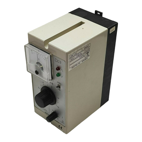
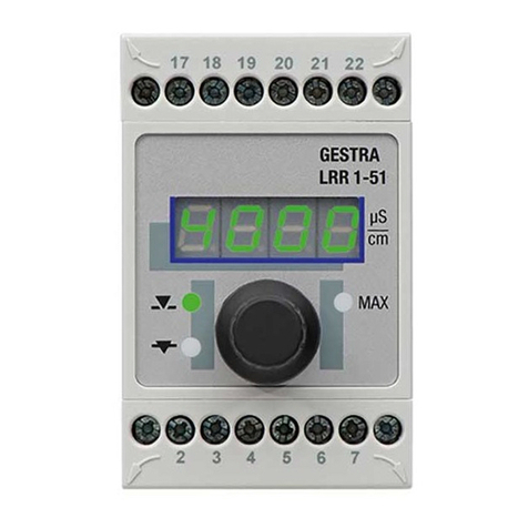
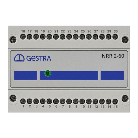
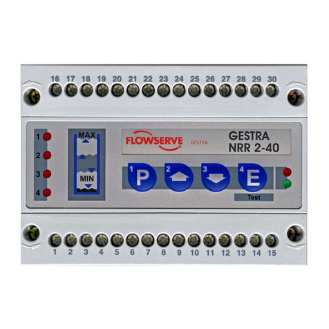
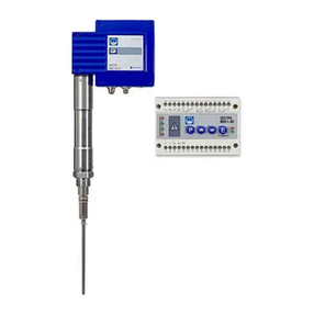
The LRR 1-50, LRR 1-51 conductivity controller is used in combination with the LRG 1.-.. conductivity
electrodes and the LRGT 1.-.. conductivity transmitter as a conductivity controller and limit switch, e.g. in
steam boilers and hot water installations and in condensate and feedwater tanks. The conductivity con-
troller indicates when MAX conductivity is reached and opens or closes a continuous blowdown valve.
Conductivity controllers can be combined in a circuit with conductivity electrodes or transmitters as
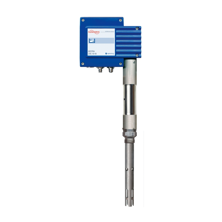
follows: LRR 1-50 conductivity controller with LRG 12-2, LRG 16-4, LRG 16-9, LRG 17-1 and LRG 19-1
conductivity electrodes; LRR 1-51 conductivity controller with LRGT 16-1, LRGT 16-2, LRGT 16-3,
LRGT 16-4, LRGT 17-3 and LRGT 17-1 conductivity transmitters.
Continuous blowdown
As the boiler water begins to evaporate, the concentration of non-volatile total dissolved solids (TDS)
left behind in the boiler increases over time as a function of steam consumption. If the TDS concentra-
tion exceeds the limit defined by the boiler manufacturer, foaming and priming occurs as the density of
the boiler water increases, resulting in a carry-over of solids with vapour into steam lines and super-
heaters. The consequences are adverse effects on reliability and severe damage to steam generating
units and pipes. To keep the TDS concentration within admissible limits, a certain portion of boiler
water must be removed continuously or periodically (by means of a continuous blowdown valve) and
fresh feedwater must be added to the boiler feed to compensate for the water lost through blowdown.
To determine the TDS in the boiler water, its electrical conductivity is measured in μS/cm, although
some countries also use ppm (parts per million) as the unit of measurement.
Conversion 1 µS/cm = 0.5 ppm.
Operating position of the continuous blowdown valve
It is common practice to use the continuous blowdown valve to remove a certain amount of water from
the boiler to keep the TDS within the desired limits. This means that the valve must be slightly open
during operation, so that this water can be discharged (valve in OPERATING position). This operating
position can be set on the continuous blowdown valve, and the amount of boiler blowdown can be
established with the aid of the valve capacity charts.
Switching hysteresis
The controller works as a 2-position controller, which means that the continuous blowdown valve is
moved into OPEN position when the set point is reached. The conductivity must then decrease. Once it
has fallen to a level that is lower than the set point minus the defined hysteresis, the valve is moved into
OPERATING position.
Temperature compensation
The electrical conductivity of water changes as the temperature falls or rises. To obtain meaningful
readings, it is therefore necessary to base the measurements on the reference temperature of 25 °C,
and to correct the measured conductivity using the temperature coefficient tC.
Cell constant and correction factor
The geometric variable (cell constant) of the conductivity electrode is taken into account when calculating
the conductivity. However, this constant may change during operation, e.g. due to dirt deposits on the
measuring electrode. Deviations can be compensated by changing the correction factor CF.
Flushing the continuous blowdown valve
The continuous blowdown valve can be flushed automatically to prevent it from sticking. In this case,
the continuous blowdown valve is actuated at intervals (flushing interval Si) and opened for a certain
time (flushing time Sd). After the flushing time, the valve is moved into the OPERATING position or into
the required control position.
Glossary
