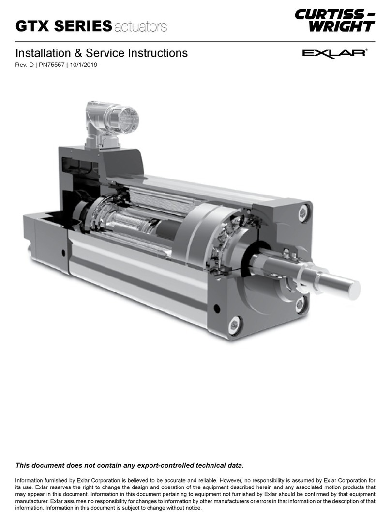
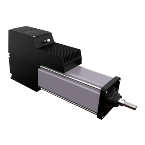
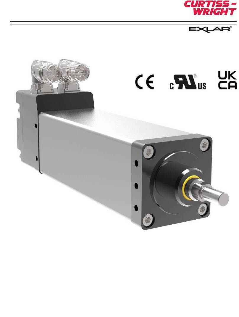
Curtiss-Wright Tritex EVA080 Installation and maintenance instructions

This document does not contain any export-controlled technical data.
Information furnished by Exlar Corporation is believed to be accurate and reliable. However, no responsibility is assumed by Exlar Corporation for
its use. Exlar reserves the right to change the design and operation of the equipment described herein and any associated motion products that
may appear in this document. Information in this document pertaining to equipment not furnished by Exlar should be conrmed by that equipment
manufacturer. Exlar assumes no responsibility for changes to information by other manufacturers or errors in that information or the description of that
information. Information in this document is subject to change without notice.
Installation & Service Instructions
Rev. A | PN84148 | 10/15/23
Tritex®EVA
Intelligent Linear Valve Actuator
Class 1, Division 2, Groups A, B, C, D
Hazardous Environment Rating

2| Tritex EVA Actuator Installation & Maintenance Instructions Curtiss-Wright | Rev A | PN84148 | 10/15/23
CONTENTS
CONTENTS
1. INTRODUCTION .................................................................................................................. 3
2. HEALTH & SAFETY CONSIDERATIONS.......................................................................... 4
3. PRODUCT INFORMATION ................................................................................................ 5
3.1. PRODUCT FEATURES ........................................................................................................................... 5
3.2. PRODUCT SPECIFICATIONS................................................................................................................ 6
3.3. LABEL & ORDERING INFORMATION ................................................................................................... 7
4. INSTALLATION.................................................................................................................... 8
4.1. PRODUCT DIMENSIONS ....................................................................................................................... 8
4.2. MECHANICAL INSTALLATION............................................................................................................... 9
4.2.1. Mounting & Mechanical Considerations ........................................................................................... 9
4.2.2. Lubrication Requirements................................................................................................................. 9
4.2.3. Actuator Cover Removal................................................................................................................... 9
4.2.4. Actuator Mounting Bolts.................................................................................................................... 9
4.2.5. Conduit Entry.................................................................................................................................... 9
4.3 ELECTRICAL INSTALLATION................................................................................................................ 10
4.3.1. Electrical Installation....................................................................................................................... 10
4.3.2. Power Source ................................................................................................................................. 10
4.3.2.1. Grid Power Supply...................................................................................................................................11
4.3.2.2. Battery and Charging Supply Systems ................................................................................................... 12
4.3.3. Conecting to Terminals ................................................................................................................... 14
4.3.3.1. Ground Connections............................................................................................................................... 15
4.3.3.2. Power Supply Wiring & Fusing ............................................................................................................... 16
4.3.3.3. Control Wiring ......................................................................................................................................... 17
4.3.3.3.1. Analog Input Connections (4-20 mA)............................................................................................. 17
4.3.3.3.2. Analog Output Connections (4-20 mA) .......................................................................................... 18
4.3.3.3.3. Digital Input (DI) & Digital Outpiut (DO) Connections.................................................................... 18
4.3.3.3.4. Digital Input Specications ........................................................................................................... 19
4.3.3.3.5. Digital Output Specications.......................................................................................................... 19
4.4. COMMUNICATIONS .............................................................................................................................. 19
4.4.1. Modbus RTU (RS-485).................................................................................................................... 19
4.4.2. PC Communication (Connecting to the Actuator)............................................................................ 20
4.4.2.1. CBL-T2USB485-M8-xxx Communication Cable...................................................................................... 21
4.5. POSITION TRACKING ON POWER LOSS .......................................................................................... 22
4.6. EXPERT PC TOOL QUICK START........................................................................................................ 23
4.6.1. Quick Start Guide – Generic Lite..................................................................................................... 23
4.7. PRODUCT MAINTENANCE................................................................................................................... 39
4.7.1. Lubrication Renewal Procedure ...................................................................................................... 39
4.7.2. Seal Maintenance............................................................................................................................ 40
4.8. TRANSPORTATION & STORAGE INSTRUCTIONS ........................................................................... 41
4.9. PRODUCT RETURNS ............................................................................................................................ 41

4.10. CERTIFICATIONS & COMPLIANCE ................................................................................................... 41

Tritex EVA Actuator Installation & Maintenance Instructions | 3www.exlar.com | 952.500.6200
1. INTRODUCTION
The Tritex EVA actuator includes the patented and proven Exlar inverted roller screw with integrated brushless motor plus
electronics to provide a complete valve actuator solution, all housed in an environmentally sealed enclosure with hazardous
area certication.
This manual is for use with Tritex EVA080 actuators only. Installation and service instructions for other Tritex actuators can be
found at www.Exlar.com.
The following instructions must be followed when installing Curtiss-Wright, Exlar products:
• Read all instructions before installing, operating or maintaining this product
• Contact Curtiss-Wright, Exlar for any questions
• Follow all warnings, cautions, and noted instructions on, and with the product
• Qualied personnel should install, operate, update and service the product Tritex EVA Product Page

4| Tritex EVA Actuator Installation & Maintenance Instructions Curtiss-Wright | Rev A | PN84148 | 10/15/23
2. HEALTH & SAFETY CONSIDERATIONS
Safety is of paramount importance during the installation and operation of your Tritex EVA actuator. Throughout this manual,
content agged with the cautionary symbols shown below should be read carefully by installers and operators to help avoid
property damage, personal injury or death.
WARNING!
Indicates a potentially hazardous situation which could result in serious injury or death if precautions are not taken.
CAUTION!
Indicates the information following is necessary for avoiding a risk of damage to the product or other equipment.
Several general warnings and cautions follow. In addition, refer to the AGENCY APPROVALS section for Conditions of Use for
additional limits and requirements to ensure safe installation and operation
WARNING! General
Failure to follow safe installation guidelines can cause death or serious injury. Voltages and currents in the product can cause
electric shock or burns and could be lethal. Extreme care is always necessary when working with or adjacent to the product.
The installation must comply with all relevant safety legislation in the country of use. The forces created by the actuator could
be lethal or cause severe injury if proper protection is not provided to keep personnel away from moving components. Before
installing the actuator ensure that it is suitable for the intended application. Consult with Curtiss-Wright, Exlar if there are
questions prior to installation.
WARNING! System Design & Safety for Personnel
System Design and safety for personnel The actuator is intended as a component for professional incorporation into complete
equipment or a system.
WARNING! Hot Surface – Risk of Burn
Exposed surfaces of the actuator may exceed 70 °C under normal operation and can take a long time to cool, resulting in a
risk of burns when touched.
WARNING! Hazardous Area
Ensure the actuator cover is tight and properly installed before applying power to the actuator. Property damage or personal
injury may result from re or explosion if power is applied to the actuator with the cover removed in a hazardous area.
WARNING! Crush/Pinch Point
Keep hands clear of stem when power applied to actuator.

Tritex EVA Actuator Installation & Maintenance Instructions | 5www.exlar.com | 952.500.6200
3. PRODUCT INFORMATION
The Tritex EVA actuator includes the patented and proven Exlar inverted roller screw with integrated brushless motor plus
electronics to provide a complete valve actuator solution, all housed in an environmentally sealed enclosure with hazardous
area certication.
3.1. PRODUCT FEATURES
Wiring access cover
Two ¾ NPT entry points
Electronics housing
Grounding (PE) point
Modbus RTU (RS-485) programming port
Motor & roller screw housing
Valve adapter faceplate
Actuator stem

6| Tritex EVA Actuator Installation & Maintenance Instructions Curtiss-Wright | Rev A | PN84148 | 10/15/23
3.2. PRODUCT SPECIFICATIONS
Power & Control
Rated Thrust 1000 lbf (4.4 kN)
Seating Thrust
ISO Rated Thrust
1500 lbf (6.67 kN)
Rated Speed 1 in/s (24.4 mm/s) @ 24 Vdc
Stroke 4 in (101.6 mm)
Input Voltage 12-24 Vdc ±10% nominal, 9-32 Vdc max range
Input Current 12 A max
Idle Current 0.065 A enabled
Endurance & Life
Endurance Exceeds 10,000 starts, 3600+ starts per hour
Duty Class D continuous modulating, 100% duty cycle
Life Exceeds 10,000,000 cycles over 10 years
Communication & Commissioning
Serial Interface Isolated Modbus RTU (RS-485), max baud rate 38.4 k
Software Tool Free-to-download Expert PC commissioning tool
Inputs & Outputs
Digital Inputs 3 - Isolated, 9-30 Vdc
Digital Outputs 2 - Isolated, 9-30 Vdc
Analog Input 1 - Isolated, 4-20 mA, position / thrust demand
0.1% resolution, 0.5% linearity over temperature range
Analog Output 1- Isolated, 4-20 mA, position / thrust feedback
0.1% resolution, 0.5% linearity over temperature range
Environment & Mounting
Enclosure NEMA 4X, IP66
Operating temperature -40 to 149 °F (-40 to 65 °C)
Ambient storage temperature -58 to 185 °F (-50 to 85 °C)
Mounting Face mount, any orientation, with valve adapter
Noise Less than 70 dB operation
Weight 17.2 lbs. (7.8 kg)
Standards
Approvals cCSAus Class 1, Division 2, Group A, B, C, D, T5
Product standards ISO 22153, RoHS

Tritex EVA Actuator Installation & Maintenance Instructions | 7www.exlar.com | 952.500.6200
3.3. LABEL & ORDERING INFORMATION
A product label is attached to each actuator under the conduit entry points.
Figure 1 - Typical Label Specications
Position Sensing
Sample Product Number: EVA080-100-01-B-AA-H-R-XXXX
Stroke Length
BBB D F
Rod End Thread
Actuator Series &
Frame Size
(EVA) AAA
Motor | Drive
Screw Lead
CC EE G
Communication
HIJK
Options
Ordering Info
Actuator Series
EVA = Electric Valve Actuator,
Linear
AAA = Actuator Frame Size
080 = 3.1 in (80 mm)
BBB = Stroke Length
100 = 4 in (100 mm)
CC = Screw Lead
01 = 0.1 in (2.54 mm), Roller
Screw lead
D = Rod End Thread
B = Female Metric, M12x1.25
EE = Motor | Drive
AA = Standard Motor (A),
Standard Servo Drive (A),
12-24 Vdc Input
F = Position Sensing
H = Absolute Position Sensing
A = Absolute Position Sensing
on Powerloss (Battery Backup)
G = Communication
R = Standard Modbus RTU
(RS485)
HIJK = Options
NNNN = None

8| Tritex EVA Actuator Installation & Maintenance Instructions Curtiss-Wright | Rev A | PN84148 | 10/15/23
4. INSTALLATION
The Tritex EVA actuator is a complete motion system that combines a linear actuator, servo motor, and servo drive. The
electrical to mechanical power conversion and control device are contained in the actuator.
4.1. PRODUCT DIMENSIONS
Tritex EVA080
08.9 TPN41-4/3
)x2(
82.1
82.1
05.11
69.
23.1
831.
000.2
+
-
000.
300.
035.3
056.2
018.8
.C.B635.3
°03
035.3
060.7
B2-CNU02-4/1
.niMpeeD365.0x
decapS )x4(
584SR

Tritex EVA Actuator Installation & Maintenance Instructions | 9www.exlar.com | 952.500.6200
2X 3/4 NPT
Conduit
Entry Points
4.2. MECHANICAL INSTALLATION
4.2.1. Mounting & Mechanical Considerations
Every eort should be made to properly align the actuator main rod to the valve stem. Any misalignment will decrease the life
of the components within the actuator and may create problems within the application associated with misalignment such as
rod seal leakage.
The Tritex EVA080 can be mounted in any orientation without consideration of performance, but typically the actuator is
mounted vertically, rod end down.
4.2.2. Lubrication Requirements
The actuator is shipped from the factory fully greased and ready for installation. Typical applications will not require
relubrication during the life of the actuator. Exlar recommends using Tribolube 12T, a high performance, extreme-pressure
grease. The unique physical properties of the synthetic base oil provide outstanding protection against wear, rust, corrosion
and high or low-temperature degradation. Tribolube 12T allows for very low starting and running torque values.
4.2.3. Actuator Cover Removal
There are 8 captured bolts on the cover, M8x 1.25, must be tightened to 108 in-lbs., (12.2 Nm). Add 1 in (2.54 mm) clearance
for cover removal and wiring. Always replace cover before applying power in a hazardous location. The clearance distance is
only for cover removal. It is recommended to leave enough room for electrical installation and applicable guidelines followed.
4.2.4. Actuator Mounting Bolts
The actuator is mounted to the valve adapter using 4 bolts, ¼-20 UNC-2B, equally spaced and must be engaged at a minimum
of 0.5 in (12.7 mm) and must be tightened to 62 in-lbs. (7 Nm).
4.2.5. Conduit Entry
The actuator includes 2 conduit entry ports threaded ¾” NPT. Conduit or cable glands should be tightened to 2-3 turns past
nger tight or to 54 in-lbs. (6.1 Nm) of torque. Remove any transit plugs and seal unused entry points with threaded plugs.
NOTE: Power and signal wiring should be routed through dierent conduit entry points. If power and signal wires are routed
through the same conduit entry point the plastic cap lug should be discarded and replaced with an approved plug and a
minimum of ve threads of engagement.
If the actuator is installed in a hazardous area only appropriately certied conduit, seals, and cable glands should be used. Any
unused entry points must be sealed with certied threaded plugs without the use of an adapter.

10 | Tritex EVA Actuator Installation & Maintenance Instructions Curtiss-Wright | Rev A | PN84148 | 10/15/23
CAUTION!
Excessive side load on the actuator output rod will dramatically reduce the life of the actuator and should be avoided. Side
load can result from misalignment or loading that is not in line with the actuator output rod.
CAUTION!
Care should be taken not to exceed the physical travel limits of actuators. Doing so will cause the actuator to end-crash
internally. End crashes can physically damage the roller screw and the internal components of the actuator.
CAUTION!
If the actuator is mounted with the rod end facing up, it must be external protected from exposure to rain. The actuator is
provided with a rod seal which has been tested to NEMA 4X enclosure ratings however long-term wear or misalignment can
cause degradation of the seal and eventually lead to moisture.
4.3 ELECTRICAL INSTALLATION
4.3.1. Electrical Installation
Connections to the actuator are made using the two ¾” NPT entry ports dened in the mechanical installation section (Conduit
Entry 4.2.7). Typically, one port is used for input power wiring while the other entry port is used for control wiring. The terminal
blocks can be accessed by removing the cover (procedure dened in mechanical installation section (Actuator Cover Removal
4.2.5).
WARNING!
For hazardous locations, install wiring and/or cable glands
that are suitable for the environment. Environment examples
include hazardous locations, ingress protection, and
temperature. Failure to use suitable components may results
in personal injury or property damage from re or explosion.
Wiring connections must be made in accordance with the
local, regional, and national codes that apply to the hazardous
area approval. Failure to use suitable components may results in
personal injury or property damage from re or explosion.
4.3.2. Power Source
The power source nominal voltage is 12-24 Vdc. The maximum operating range is 9-32 Vdc. The power source can be a
battery or a DC power supply. If a power supply is used either a regulated or non-regulated supply can be used, if the above
ranges are always maintained. Regulated power supplies typically have built in protections such as over current or overvoltage
and are recommended.
2X 3/4 NPT
Conduit
Entry Points

Tritex EVA Actuator Installation & Maintenance Instructions | 11www.exlar.com | 952.500.6200
4.3.2.1. Grid Power Supply
The maximum current required from the power supply is dependent on three factors: supply voltage, thrust required to
operate the valve and the operating speed. Speed limit is a setup parameter within the actuator. The charts below show the
maximum (peak) power supply current draw for various force and speed combinations for 12 Vdc and 24 Vdc supplies. Since
the maximum speeds only occur for a short period of time which is dependent on speed and stroke distance, the peak input
current draw is also for a short time, it is not a continuous value. When selecting a power supply, assure that it can supply 150
-200% of the maximum current needed for the required time to be sure abnormal conditions do not cause the power supply to
fault.
Power Supply Sizing Example
The example below can be used as a conservative estimate of power draw used for power supply sizing. Often in the real
world the power draw is much lower which is covered in a later section.
The example valve requires no more than 500 lbf (2.22 kN) seating thrust and the desired close speed is 0.5 in/s (12.7
mm/s). The ISO 22153 standard for a linear valve load prole states that the seating thrust should account for the last 10%
of the travel and the average thrust should be 30% of seating thrust. So, in this example using 500 lbf seating thrust, the
average thrust will be 250 lbf. The seating thrust amps should be used to ensure the power supply has a peak available amp
but ill not represent total amp draw. Using the graph below a 500 lbf seating thrust requires a power supply with 2.6 Amps
available. Some power supplies provide overload Amps. The typical power supply overload Amps can be used for seating
thrust purposes. The 250 lbf average load thrust should be used to select a power supplies rated Amps. In this case that is
approximately 1.24 amps. The power supply must be rated above 1.24 amps and provide and current overload or rated current
above 2.6 amps.
Figure 2 - Input Current Requirements at 24 Vdc
0
2
4
6
8
10
12
14
16
18
0 100 200 300 400 500 600 700 800 900 1000 1100 1200 1300 1400 1500
Input Current (A)
Output Thrust (lbf)
24 Vdc Input Current vs Output Thrust at Various Speeds
Enabled Hold at 24 Vdc Modulate (0.1 in/s) at 24 Vdc 0.25 in/s at 24 Vdc 0.5 in/s at 24 Vdc 0.75 in/s at 24 Vdc 1 in/s at 24 Vdc

12 | Tritex EVA Actuator Installation & Maintenance Instructions Curtiss-Wright | Rev A | PN84148 | 10/15/23
Valve Application Typical Current Requirements
The example above provides guidance for selecting a power supply. Additional current draw testing has been conducted using
the ISO 22153 valve thrust load provide where 10% of the stroke is at seating thrust and 90% of the stroke is at 30% of seating
thrust. The chart below shows the measured current draw for dierent seating thrusts at dierent valve closing speeds. Using
the example above of 500 lbf seating thrust a 3 in stroke move at 0.5 in/s valve closing speed would require 1.08 amps total to
close / open the valve.
Figure 3 - Input current requirements at 12 V
0
5
10
15
20
25
0 100 200 300 400 500 600 700 800 900 1000 1100 1200 1300 1400 1500
Input Current (A)
Output Thrust (lbf)
12 Vdc Input Current vs Output Thrust at Various Speeds
Enabled Hold at 12 Vdc Modulate (0.05 in/s) at 12 Vdc 0.1 in/s at 12 Vdc 0.2 in/s at 12 Vdc 0.3 in/s at 12 Vdc
4.3.2.2. Battery and Charging Supply Systems
The Tritex EVA080 is designed to work with a battery and charging system. With a battery system there is typically less
concern about the maximum (peak) current drawn, as batteries can supply high current, but more concern about the average
current draw. The peaks from the chart below only occur during valve seating or unseating. The current required for holding
a given thrust is about 30% of the zero speed or modulating current shown in the chart. To keep the input current as low as
possible on battery systems with solar charging set the actuator speed to the maximum allowed by the available voltage.
Ripple Voltage from battery charging system is a factor that needs to be considered. The maximum peak ripple voltage
allowed is 36 Vdc peak. Any instantaneous voltage above 38 Vdc will cause the Tritex EVA080 to fault out on High Voltage
Fault.

Tritex EVA Actuator Installation & Maintenance Instructions | 13www.exlar.com | 952.500.6200
0
0.5
1
1.5
2
2.5
3
3.5
4
4.5
0 100 200 300 400 500 600 700 800 900 1000 1100 1200 1300 1400 1500
Average Input Current (A)
Rated Output Thrust (lbf)
12 Vdc ISO 22153 Move, 3 inch stroke, extend and retract, 10% of stroke @ 100% thrust, 90% of stroke @ 30% thrust, 8.3
in/s² accelera�on.
Average Input Current vs Thrust.
0.1 in/s at 12 Vdc 0.2 in/s at 12 Vdc 0.3 in/s at 12 Vdc
1100 1200 1300 1400 1500
1 in/s at 24 Vdc
0
1
2
3
4
5
6
0 100 200 300 400 500 600 700 800 900 1000 1100 1200 1300 1400 1500
Average Input Current (A)
Rated Output Thrust (lbf)
24 Vdc ISO 22153 Move, 3 inch stroke, extend and retract, 10% of stroke @ 100% thrust, 90% of stroke @ 30% thrust, 8.3
in/s² accelera�on.
Average Input Current vs Thrust.
0.25 in/s at 24 Vdc 0.5 in/s at 24 Vdc 0.75 in/s at 24 Vdc 1 in/s at 24 Vdc
Figure 4 - 12 Vdc Average Inut Current vs Thrust
Figure 5 - 24 Vdc Average Inut Current vs Thrust

14 | Tritex EVA Actuator Installation & Maintenance Instructions Curtiss-Wright | Rev A | PN84148 | 10/15/23
Figure 6 - Tritex EVA080 Wiring Overview
Internal Power
Supplies and
Motor Drivers
24 V Power
24 V Common
Output 1
Output 2
Input 1
Input 3
Input 2
Control Electronics
and Other Low
Voltage Circuits
DC Power -
IO-
RS485 +
RS485 -
IO+
PE PE
4-20 mA OUT +
4-20 mA IN +
4-20 mA IN -
4-20 mA OUT -
RS485Common
PE
DC Power +
RS485 +
RS485 -
PE
PE
PE
J3
J2
J1
J5
J6
1
1
2
2
3
3
4
4
5
5
6
6
1
2
7
8
7
10 kOhm
10 kOhm
Screw Terminal
Output Load
Output Load
RS485+*
RS485-*
M8 RS485
Tritex EVA080
4.3.3. Connecting to Terminals
Connections made to the Tritex EVA are made with tool-free lever-lock terminals. To make a connection, with your nger
actuator the lever of the desired terminal. The lever will lock open. Insert the conductor into the terminal (conductors should
have an anti-splaying method applied such as ferrules, crimples or other methods). Once inserted, with a nger, actuate the
terminal to the close position to clamp the conductor in place. One conductor per clamping unit is recommended.

Tritex EVA Actuator Installation & Maintenance Instructions | 15www.exlar.com | 952.500.6200
Internal Ground Connection
External Ground Connection
Figure 7 - Ground wire size should be a minimum of 14 AWG and not smaller than the DC +/- power wires.
Description Location Terminal #
DC Power - J1 1
DC Power + J1 2
PE Screw Terminal
4-20 mA OUT - J2 1
4-20 mA OUT + J2 2
PE J2 3
4-20 mA IN - J2 4
4-20 mA IN + J2 5
PE J2 6
RS485- J2 7
RS485+ J2 8
IO- J3 1
IO+ J3 2
Output 2 J3 3
Output 1 J3 4
Input 3 J3 5
Input 2 J3 6
Input 1 J3 7
4.3.3.1. Ground Connections
Internal and external grounding terminals are provided. For the internal connection the ground wire is intended to be run
through the conduit and connected to ground near the power source or in the power panel. The second ground connection is
External and is intended to provide a local ground connection.

16 | Tritex EVA Actuator Installation & Maintenance Instructions Curtiss-Wright | Rev A | PN84148 | 10/15/23
CAUTION!
Ground conductors must be installed before power is applied.
4.3.3.2. Power Supply Wiring & Fusing
CAUTION!
Reversing polarity of the Power (+) and Power Common (-) will cause a short circuit, which must be protected by the external
fuse. See fusing details below. If the proper fuse is not installed the actuator could be permanently damaged.
If the application does not require maximum power, and the power source is a UL Recognized power supply with current
limiting protection the wire gauge can be reduced with a corresponding reduction in fuse rating. The power supply connections
are a tool-free lever-actuated connection. Use ngers to open the terminal connection. Insert power wires and closing levers
with securing the wires.
WARNING!
If the wire gauge for power wiring is reduced the fuse Amp rating must also be reduced in accordance with wire size and local
regulations.
Power Input Fuse Conductor
12-24 Vdc 15 Amp Bussmann KTK
R Class CC or equivalent
14 AWG (2.5 mm²) 105 °C min.
DC Power -
PE
PE
DC Power +
J1
1
2
Screw Terminal
12-24 Vd c
Source
Grounding
power source
negative is
optional
PE
Internal Power
Supplies and
Motor Drivers
Figure 8 - Power Supply Wiring Figure 9 - Power supply wiring example
WARNING!
All installations should provide a method of removing the power source during an emergency shutdown condition.

Tritex EVA Actuator Installation & Maintenance Instructions | 17www.exlar.com | 952.500.6200
Figure 11 - Connection to the low side controller
Control Electronics
and Other Low
Voltage Circuits
4-20mA OUT +
4-20mA IN +
4-20mA IN -
4-20mA OUT -
RS485+
RS485-
PE
PE
J2
1
2
3
4
5
6
7
8
RS485+*
Low-Side
4-20 mAController
12-24V Com
+12-24Vdc
Description Specication
Input Range 2 - 22.5 mA, Loss of Signal Condition <2.0 mA
Voltage Drop @ 20 mA 9 V typical
Input Resolution >14 bits over 4-20 mA range (1.6 Amps DC value / uA
Update Rate 0.5 ms
Analog Input Specication (4-20 mA)
4.3.3.3. Control Wiring
The I/O on the Tritex EVA080 includes one 4-20 mA input, one 4-20 mA output, three digital inputs, and two digital outputs.
All I/O circuits are isolated from each other as well as all other actuator I/O, ground, and commons. Analog and digital input
/ output connections use tool-free terminal blocks, which can be easily manipulated by hand. Control terminal blocks accept
26-14 AWG wires.
4.3.3.3.1. Analog Input Connections (4-20 mA)
The 4-20 mA input is a two-wire circuit. A small amount of power from the 4-20 mA signal is used to generate the internal
power supplies needed for the isolation of the input section. This allows the input to oat with the transmitter or loop power
supply without inference from the other actuator grounds or commons. The power supply starts up when the input reaches 2
mA. When the 4-20 mA loop is unpowered, the software reads an o-scale value that should be congured to indicate a “Loss
of Signal” condition.
Control Electronics
and Other Low
Voltage Circuits4-20mA OUT +
4-20mA IN +
4-20mA IN -
4-20mA OUT -
RS485+
RS485-
PE
PE
J2
1
2
3
4
5
6
7
8
RS485+*
+12-24Vdc
High-Side
12-24V Com
4-20 mAController
Figure 10 - Connection to the high side controller

18 | Tritex EVA Actuator Installation & Maintenance Instructions Curtiss-Wright | Rev A | PN84148 | 10/15/23
4.3.3.3.2. Analog Output Connections (4-20 mA)
The 4-20 mA output is a two-wire circuit; it requires an external loop supply of 12-30 Vdc to generate the isolated supply
voltages needed. The Tritex EVA circuit requires 8 V to operate; therefore, the max impedance the output can drive
is dependent on the loop supply voltage. If the actuator is powered down, the output goes to an o-scale low output
approximately 2 mA.
10 k
Ohm
10 kOhm
24 V Power
24 V Common
Output 1
Output 2
Input 1
Input 3
Input 2
IO-
IO+
J3
1
2
3
4
5
Output Load
Output Load
6
7
Auxillary/External Power
Supply for Digital IO
PLC Output or Other
Signal Loads
PLC Input or Other
Signal Sources
Loop Supply Voltage Maximum Impedance @ 20 mA Minimum Impedance @ 20 mA
12 V 200 Ω 200 Ω
15 V 350 Ω 200 Ω
24 V 800 Ω 200 Ω
30 V 200 Ω 200 Ω
Figure 12 - Examples of digital IO eld wiring
Control Electronics
and Other Low
Voltage Circuits
4-20mA OUT +
4-20mA IN +
4-20mA IN -
4-20mA OUT -
RS485+
RS485-
PE
PE
J2
1
2
3
4
5
6
7
8
RS485+*
External Controller
Loop Supply +
Loop Supply -
-
12-24V
Loop Supply
+
+
-
Analog Output Specication (4-20 mA)
4.3.3.3.3. Digital Input (DI) & Digital Output (DO) Connections
All the Tritex EVA I/O are optically isolated from the main power supply and each IO section is isolated from each other. All
the digital inputs have a common return connection at the IO- terminal and require a positive voltage on the Input terminals
to turn on. The outputs have a common positive connection at the IO+ terminal and produce a positive voltage on the Output
terminals when they are on.

Tritex EVA Actuator Installation & Maintenance Instructions | 19www.exlar.com | 952.500.6200
Description Specication
Input Voltage 0-30 Vdc
On State Voltage Range 8-30 Vdc
O State Voltage Range 0-7 Vdc
On State Current
10 V (min)
24 V (nominal)
30 V (maximum)
3.5 mA
5.1 mA
5.7 mA
Nominal Impedance (24 V) 4.8 kΩ
O State Current (max) 3.5 mA
Update Rate 1 ms (typical)
Description Specication
Operating Voltage Range 0-30 Vdc
On State Maximum Continuous
Current
100 mA
On state voltage drop @ 50 mA 0.5 V typical
Short Circuit Protection (auto reset) 0.5 A
Update Rate 1 ms (typica)
4.3.3.3.4. Digital Input Specications
4.4. COMMUNICATIONS
Communications with the Tritex EVA are used for setup of the actuator.
4.4.1. Modbus RTU (RS485)
Serial communication to the actuator is provided through RS485 terminals located on the Tritex EVA control board. The serial
interface is two wire opto-isolated Modbus RTU (RS485) network. The actuator supports the Modbus RTU protocol for access
to all drive parameters (see Modbus Parameter Reference). The Default baud rate is 19.2k. The default Modbus address is 1.
13
4
2
Figure 13 - M8 communications Connector
4.3.3.3.5. Digital Output Specications
Connector - Front View
Hazardous Area Explosion
Hazard. Do Not Connect
or Disconnect When
Energized
WARNING
!
WARNING! Cap must be on when ammable gases are present. Used for
Setup only. Cap should be tight during normal operation.
WARNING! Hazardous Area Explosion hazard do not connect or
disconnect when energized

20 | Tritex EVA Actuator Installation & Maintenance Instructions Curtiss-Wright | Rev A | PN84148 | 10/15/23
Figure 14 - Connecting multiple Tritex EVA actuators to Modbus RTU (RS485) master host
4.4.2. PC Communication (Connecting to the Actuator)
When using the Expert software for set-up and diagnostics a Modbus RTU (RS485) converter is required to interface between
one of the PC communication ports and the actuator. This can be a USB to Modbus RTU (RS485) converter, such as the Exlar
CBL-T2USB485-M8-006 (6 ft length) or CBL-T2USB485-M8-015 (15 ft length) any other standard Modbus RTU converter.
Modbus RTU (RS485) is a multi-drop network, so multiple devices, some of which might not be Tritex EVA actuators, may
be connected to a single Modbus master. Devices on any single network need to have unique Modbus Device ID’s before
connecting them to the network. A recommended approach to avoiding multi-drop address collisions is that in normal operation
no units have Modbus Device address 1 and any spares or additions at default address 1 so that a new or replacement unit
can be added and then the address changed to the operational address. Since multiple masters are not supported, it may be
more convenient to congure units using Expert software before nal installation.
Because Modbus RTU (RS485) at speeds supported on Tritex EVA cannot be considered a high-performance link, data
throughput and latency issues will limit the capabilities of Modbus RTU (RS485) as a multi-drop network. Due to biasing
resistors at each node and data throughput limitations, the maximum number of devices on a network should not exceed eight.
A multi-drop network can be useful for reporting status and changing parameters dynamically for dierent valve positions, or
for providing a single access point for Expert software connection.
Function M8 Pin Number Wire Color TTCOM J7 Terminal
RS485+ 1 Brown 6
RS485- 3 Blue 5
RS485 COM 4 Black 4
PE 2 Drain 3
EVA080
# n
(8 max)
EVA080
# 2
EVA080
# 1
Modbus Master
PC, HMI, PLC etc.
485+ 485- Ref
Table of contents
Other Curtiss-Wright Controllers manuals

Curtiss-Wright
Curtiss-Wright Compact CHAMP-AV IV User manual

Curtiss-Wright
Curtiss-Wright EL30 Manual

Curtiss-Wright
Curtiss-Wright EXLAR GTX Series Installation and maintenance instructions

Curtiss-Wright
Curtiss-Wright EXLAR GTX Series Installation and maintenance instructions

Curtiss-Wright
Curtiss-Wright EXLAR Tritex II AC Manual
Popular Controllers manuals by other brands

MSA
MSA ModCon 75 instruction manual

Radio Shack
Radio Shack TRS-80 owner's manual

Thermo Scientific
Thermo Scientific ALPHA COND 560 manual

Konica Minolta
Konica Minolta IC-301 user guide

Advanced Technologies
Advanced Technologies M7000 Series User and technical manual

YASKAWA
YASKAWA AO-A3 User & installation manual