ElectroMaax Marine Watermaker Series Instruction manual

1V2
ElectroMaax Inc.
Marine Watermaker Series
SolarMaax 10
12 or 24 Volt System
INSTALLATION, OPERATION
&
MAINTENANCE MANUAL
Table of Contents
Toll Free: 1-866-945-8801
Fax: 1-905-563-8806
Web: www.electromaax.com
Email: sales@electromaax.com
US Customers
Electromaax
6405 Inducon Drive West
Unit 5
Sanborn NY 14132
Canadian and
International Customer
Electromaax
5552 King Street
Lincoln,
ON, L3J 1N6

2V2
Table of Contents
Introduction __________________________________________________ 3
General Warnings and Notices _____________________________________4
Specifications _________________________________________________ 5
Parts List ______________________________________________________ 7
Configurations _________________________________________________ 8
System Overview________________________________________________ 9
Installation Instructions___________________________________________10
Component Descriptions in order of water flow _______________________ 11
Intake Seacock ________________________________________________ 11
Sea Strainer ____________________________________________________11
Fresh Water Flush Filter Assembly__________________________________ 12
Feed Pump Assembly____________________________________________ 13
Prefilter Status Gauge ___________________________________________ 15
Accumulator Tank_______________________________________________ 15
Clark Pump 3G__________________________________________________ 16
RO membrane and Pressure Vessel _________________________________ 17
Control Panel __________________________________________________ 18
3 Way Service Valves ____________________________________________ 19
Brine Discharge Through Hull ____________________________________ 19
Optional Tank Selector Valve ______________________________________ 20
Handheld Salinity Sensor_________________________________________ 20
Mounting the Components________________________________________ 22
System Plumbing Diagram ________________________________________ 23
Low Pressure Tube Fittings________________________________________ 24
Electrical ______________________________________________________ 26
Commissioning _________________________________________________ 29
Normal Start Up and Run _________________________________________ 30
Shut Down and Flush Options _____________________________________ 31
Long Term Storage and Restart____________________________________ 32
Pre-Filter Service_______________________________________________ 33
Membrane Cleaning_____________________________________________ 34
Membrane Replacement_________________________________________ 35
Module Dimensions_____________________________________________ 40
Troubleshooting________________________________________________ 41

3V2
INTRODUCTION
The team at ElectroMaax thanks you for your purchase of our SolarMaax 10
reverse osmosis watermaker with Auto Flush, and the latest in energy recovery
technology; the Clark Pump 3G.
The addition of a low energy watermaker can be a life changing upgrade for your
cruising experience. Used properly, you will never have to go out your way just to
get questionable and/or expensive water or have to lift jerry cans out of the
dingy. The SolarMaax 10 can easily make enough for you and your crew to
shower every day, in addition it can pay for itself by being able to rinse salts off
your boat and gear, reducing maintenance and replacement costs.
The SolarMaax 10 design is based on decades of real-world product testing and
engineering from both Marine and Military applications ranging from supporting
military operations in the mountains of Afghanistan to serious offshore yacht
racing, as well as tranquil anchorages around the world.
We are confident that you will be completely satisfied with your new system and
stand behind our product with an industry leading warranty and customer
support.
4V2
GENERAL WARNINGS AND NOTICES
There are several things which the installer or operator of the SolarMaax 10 can do incorrectly,
which can seriously damage the SolarMaax 10 water maker, dramatically shorten the
operational life span of the system, and in some cases cause personal injury. Knowing the
things to avoid is critical to a good SolarMaax 10 installation and operation. We will cover the
following items again during the appropriate section later in the manual, however, due to their
importance it is worth giving the following items extra attention.
WARNING: THE SOLAR MAAX 10 IS DESIGNED TO BE USED IN TYPICAL SEA WATER.USING TASTE TO
TEST THE QUALITY OF THE PRODUCT WATER ONLY WORKS WITH A SEA WATER FEED.OPERATING IN FRESH
WATER WITHOUT STERILIZING THE PRODUCT COULD RESULT IN SICKNESS OR DEATH.
WARNING: WHEN DISASSEMBLING THE PRESSURE VESSEL,DO NOT TOUCH THE TREADS ON THE END OF
THE TUBE.THERE MAY BE FIBERGLASS SPLINTERS.
NOTICE: NEVER ALLOW CHLORINATED WATER TO COME IN CONTACT WITH THE RO MEMBRANES.
OXIDANTS SUCH AS CHLORINE AND/OR BLEACH WATER WILL PERMANENTLY RUIN THE RO MEMBRANE.
NOTICE: NEVER RUN THE SolarMaax 10 IN OILY WATER.OIL WILL PERMANENTLY RUIN THE RO
MEMBRANE.
NOTICE: DO NOT INSTALL THE RO MEMBRANE MODULE IN AN AREA WHERE THE RO MEMBRANES CAN
BECOME HEAT SOAKED TO TEMPERATURES ABOVE 113°F/45℃
NOTICE: THE RO MEMBRANE MODULE IS SHIPPED CONTAINING A STORAGE/PRESERVATIVE SOLUTION
WHICH MUST BE PURGED
NOTICE: GOOD ELECTRICAL SUPPLY TO THE FEED PUMP IS MANDATORY FOR PROPER SYSTEM
OPERATION.
NOTICE: NEVER USE A 5MICRON” CARBON” FILTER IN PLACE OF THE SUPPLIED 5MICRON
PREFILTER ELEMENT.
NOTICE: ONLY USE THE STORAGE CHEMICAL SUPPLIED BY ELECTROMAAX.OTHER BRANDS MY DAMAGE
THE SYSTEM.

5V2
SOLARMAAX 10 SPECIFICATIONS
Production Rate:8-10 Gallons per hour, 30-38 liter per hour:
The production rate is set by the displacement of the Clark Pump 3G energy recovery device and the
feed flow rate. The SolarMaax 10 uses a 10% displacement Clark Pump 3G so 10% of the feed water
flow is turned into product water. Water temperature and salinity affects operating pressure but has
little effect on production rate. Changes in feed flow does have an effect, the more feed flow the more
product. Supplying good voltage to the feed pump gives the best production rate. Running the system
while the batteries are bulk charging gives highest production rates.
RO Membrane:
The SolarMaax 10 Watermaker is equipped with DOW Filmtec® RO Membrane(s)
Membrane Type: Polyamide Thin-Film Composite
Model: SW2521 or SW2540
Range of Operating Pressures: 650 to 1000 psi (45 to 69 bar)
Normal Operating Pressure: Set by feed water conditions and feed flow rate.
Salt Rejection rate: 99.4%
Maximum Operating Temperature: 113°F (45°C)
Minimum Storage/Operating Temp: 32°F (0°C)
Maximum Operating Pressure: 1,000 psi, (69 bar)
Maximum Pressure Drop: 15 psi (1 bar)
pH Range, Continuous Operation: 2-11
pH Range, short-term cleaning: 1-12
Free Chlorine Tolerance: <0.1ppm
Electrical Power Requirements:
8.0 –10.0 amps @ 12.5-14.4 VDC
4.0 –5.0 amps @ 25.0 –28.8 VDC
The Clark Pump Third Generation (3G) Hydraulic Pressure Intensifier:
Manufactured by ElectroMaax for marine and military use. The Clark Pump 3G uses the Feed/Boost
pump flow pressure to intensify the pressure of the flow through the RO membranes high enough for
reverse osmosis to occur. There are no electrical components.
Displacement: 10 %
Feed Flow range: 1.0 gpm (3.78 lpm) to 4.0 gpm (15.14 lpm)
Maximum Inlet pressure:
up to 125 psi (8.6 bar)
Maximum Working Pressure: 1000 psi (68.9 bar)
Maximum operating temperature:
113°F (45℃)
Maximum storage temperature: 140℉(60.0℃)
Pump Dimensions: 26.38” (67cm) W, 5.75” (14.6cm) D, 8.0” (20.32cm) H
Pressure Relief Valve: Manually open ½ turn for priming and servicing
Feed Pump:

6V2
Motor: Permanent magnet type, fully enclosed, fan cooled, 1/8 hp
Pump Body: Thermo plastic
Pump Type 3 chamber diaphragm
Typical Amp Draw: 8 to 10 amps, 12VDC 4 to 5 amps 24VDC
Recommended fuse size: 15 amps, 12VDC 7.5 amps, 24VDC
Flow Rate 1.8 gpm (6.8 lpm) open flow
Pressure Vessel:
Filament wound fiberglass/epoxy compound with non-metallic wetted surfaces. Easily removeable end
caps for membrane replacement with larger that standard internal porting and fittings for increased
energy efficiency.
The most compact complete assembly available
Max pressure 1000 psi (69 Bar)
Burst pressure 3000 psi (207 Bar)
Prefilter and Auto Fresh Water Flush Filter housings:
Industry standard, 10 inch, plastic, filter housings. Accepting 9.75” by 2.5” high flow carbon filter
elements.
Clark Pump 3G and Pressure Vessel Assembly:
Dimensions: 16.3” (41.3 cm) W, 24.8” (63.0 cm) L, 9.1” (23.1 cm) H
Weight: 34.2 lbs. (15.5 kg)
Feed Pump Assembly:
Dimensions: 13.2” (33.5 cm) W, 8.63” (21.9 cm) D, 13.1” (33.2 cm) H
Weight: 11.2 lbs. (5.1 kg)
Shipping:
Level 1 with 21” Membrane: ships in 2 boxes
Box 1 –18”(45.7 cm) x 18”(45.7cm) x 14”(35.6) weight: 26 lbs.
Box 2 –29”(73.7cm) x 17”(43.2cm) x 12”(30.5cm) weight: 42 lbs.
Level 1 with 40” Membrane:
1 box 48”(122cm) x 18”(45.7cm) x 16”(40.6cm) weight: 65 lbs.

7V2
15) Handheld Salinity Sensor
16) Filter Wrench
17) Tubing Cutter
18) Tube Extractor Tool
19) Teflon Tape
20) Silicone Grease Packet
21) Container Memstor
22) 3/4” NPT to 3/4” Hose Barb –(Inlet Strainer)
23) 3/4” Check Valve –(Attached, Flush System)
24) 5/8” Tube Tee –(Flush system)
25) 2X 1/2” 3 way Service Valves (Service Access)
26) 3X 3/4” NPT to 5/8” Tube Fitting (Strainer and
Check Valve)
27) 3X 1/2” NPT to 5/8” Tube Fittings (Intake Service
Valve)
28) 4X 1/2” NPT to 1/2” Tube Fittings (Brine Service
Valve/Clark Pump)
29) 5/8” Tube Elbow Fitting (Clark Pump Stem Fitting)
30) 2X 1/4” Tube Fittings Elbow (Filter Gauge,
Attached)
31) 18X 5/8” locking rings
32) 8X 1/2” locking rings
33) 8X 1/4” locking rings
34) 1/2“NPT to 5/8” Tube Stem (Check Valve
attached)
35) 3/4” NPT to 1/2” NPT Bushing (Strainer,
Attached)
36) 3X 5/8” Tube Elbow Fittings (Feed line)
37) 2X 1/2” Tube Elbow Fittings (Brine line)
38) 4X plastic U clamps (Service Valve Mounts)
39) 3/4" NPT short nipple (Check Valve,
Strainer, Attached)
40) 2X 1/2” NPT Short Nipples (Service Valves)
41) 2X 1/8” NPT to 1/4” Tube Elbow Fittings
42) 1/2” Female Pipe to 1/2" Tube (1/2” Brine
Through Hull)
PARTS LIST:
1) Clark Pump and Pressure Vessel Assembly
2) RO Membrane Element
3) Feed Pump Assembly (Feed Pump, Prefilter, Pump Control Module)
4) Control Panel
5) Carbon Filter with Solenoid Valve for Automatic Fresh Water Flush
6) Accumulator Tank (depressurized for shipping)
7) 3/4” Sea Strainer and Mount Bracket
8) Prefilter Status Gauge
9) 30’ Coil 5/8” Tube, Black (Feed)
10) 10’ Coil 5/8” tube, Clear (Flush)
11) 20’ Coil 1/4” Tube, Black (Gauge)
12) 30’ Coil 1/2” Tube, Red (Brine)
13) 30’ Coil 1/4” Tube, Blue (Product)
14) 10” Coil Flush Valve 14/2 Power Cable
SMALL PARTS LIST:
8V2
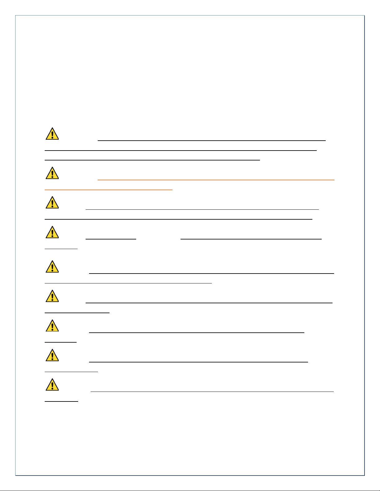
CONFIGURATIONS:
The SolarMaax 10 can be purchased with 3 different Clark Pump/Membrane configurations. All
configurations are sent with the Clark Pump and the Membrane(s) mounted together on a base frame
and plumbed together with High Pressure hoses. If a frame assembly cannot be reasonably mounted as
a unit, the Clark Pump and Membrane can be separated for custom mounting. Usually, at least one new
custom length HP hose will need to be ordered to complete the install. Membrane flow must always be
horizontal or uphill.
1. The basic single 21” membrane in a 26.5” pressure vessel. This configuration is ideal for
temperate to warm water operation and is the lightest in weight.
2. Double 21” membranes in series. One is mounted on top of the other to conserve space. Ideal
for temperate to cold water operation and where a 40” membrane would be hard to fit. This will
work in warm water with some increase in Product water TDS.
3. One 40” Membrane ideal for temperate to cold water operation. This is the most energy
efficient configuration. In warm waters the Product TDS will be higher than a 21” membrane.

9V2
SYSTEM OVERVIEW:
The SolarMaax 10 is simple to install. When all the components are connected in the right
order the system will perform as designed and give all the fresh water you need for years. Every
install is going to be different in where and how the components are mounted so forethought is
necessary for the ideal layout for your installation. If you are already familiar with watermakers
without an energy recovery device like the Clark Pump, please try to forget what you know as
much won’t apply to this system and lead you astray. Please read the instructions and don’t
make assumptions based on older types of systems.
Here is a simplified drawing of the SolarMaax 10 layout to familiarize yourself with how the
components go together:
Figure 1: Simplified Component and Plumbing Layout
When installing the SolarMaax 10 in your boat; here are the top factors to consider:
A. Make access for service, removal, and repair as easy as possible
B. Create a space where all the service valve service tubes can reach the service pail
C. Minimize the use of right-angle fittings to reduce water flow drag
D. Water will be spilled when servicing filters. Do not mount over sensitive equipment
E. Keep wire runs as short as possible and oversize the wire to minimize voltage drop
F. Though quiet for a watermaker, consider the noise when placing the components

10 V2
INSTALLATION INSTRUCTIONS:
Prior to beginning the actual installation process, please read the entire installation procedure
and take a moment to consider the following installations notes to insure the best
performance, life, ease of operation, and maintenance of your SolarMaax 10 system.
installation of your system. We are here to help you, so there’s no need to proceed with the
installation if you have any doubts or questions. We would much rather walk you through any
questions you have now, than after everything mounted in place and screw holes are drilled
into your boat! In this Manual, step by step instructions are numbered, Notes are lettered.
Installation Notes:
A. When selecting a mounting location, consider the parts that will require periodic access, such
as the Pressure Relief Valve on the Clark pump, pre-filters, membrane replacement, flush filter
and service valves
B. The boost/feed pump requires a, 15AMP fuse or breaker for 12 VDC, 7.5 amp for 24 VDC. Both
the high pressure and low-pressure water lines must be routed through the boat in such a way
that does not expose them to chafing or with tight radius bends that could cause the lines to
kink and inhibit flow.
C. Use only Teflon tape or Loctite #55 sealing cord in the installation of any water line fittings and
do not coat the first thread. Pastes type sealants are more likely to get into the system and
cause damage to the membrane and Clark Pump
D. The RO membrane can have its performance degraded by exposure to temperatures above
113°F (45°C). Select a mounting location where it will not be exposed to ambient temperatures
in excess of 113°F (45C) when the SolarMaax 10 is non-operational. If operating and being
cooled by sea water, higher ambient temperatures up to 120°F (49°C) are tolerable.
E. All of the assembly inlets and outlets are labeled clearly in the manual making the assembly
process as “plug and play” as possible. Refer to the installation schematic for a detailed
pictorial flow chart of the assembly.
F. As with most projects on a boat, the key to a good installation is planning and component
layout. We recommend that the components first be loosely (dry fit) in place for verification
of how the plumbing will go before permanently mounted.
G. Avoid sharp 90 degree fitting turns. The shortest length of tubing between two components
may not be the most efficient if it has to have hard 90-degree fittings. A longer but smoother
turning tube has less flow drag.
H. The electrical connections should be performed by a person with proper knowledge and
experience in the installation of 12 and 24 vdc systems.
I. Voltage drop at the unit will degrade performance. Use the recommended wire size or larger.
J. For further assistance, Email first to bring our techs up to speed with the issue at
11 V2
COMPONENTS IN ORDER OF WATER FLOW:
In this section, each component’s function and how it is installed is explained
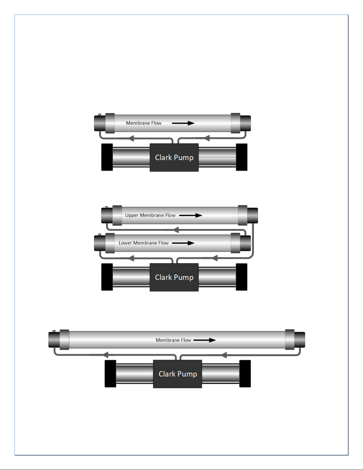
INTAKE SEACOCK:
Figure 2: ¾” Intake Seacock and Scoop, Owner Supplied
Install a dedicated ¾” seacock with a forward-facing scoop, placed as low and in the middle of
the boat as possible. Avoid placing the seacock near or downstream of a head outlet or sink
drain. Have a yard do the installation during a haul out. Sharing a through hull with another
system is not recommended, but in certain cases is acceptable. Use ¾” hose barbs that match
the valve material and ¾” ID hard walled reinforced below waterline rated hose leading to the
Sea Strainer. The Seacock and Hose are not included in the SolarMaax 10 kit
SEA STRAINER:
Figure 3: ¾” Sea Strainer and Mounting Bracket
The Sea Strainer is used to protect the check valves in the Feed Pump from being jammed by
debris. The Sea Strainer is placed between Intake Thru-hull Valve and the Feed Pump. Ideal
placement is just above the waterline but in can be placed above or below. Water will be spilled
when servicing; avoid mounting over sensitive equipment. Use ¾” hard wall reinforced rubber
hose between the Intake Through Hull and Sea Strainer. Make sure there is enough room below
the bowl for removal clearance. After selecting a location, screw down the mount bracket.
Identify the flow direction by the arrow on the housing then install the hose and tube fittings
through the bracket into the strainer body. The fittings hold the strainer body in the bracket.
When servicing the strainer, be careful not to lose the bowl gasket. Make sure the Strainer Bowl
is screwed tight, so no air is allowed to enter.
Arrow on housing shows flow direction

12 V2
FRESH WATER FLUSH ASSEMBLY:
Figure 4: Fresh Water Flush Assembly
The Auto-Flush function is used to flush seawater out of the system after use. A carbon filter is
used to remove any chlorine that may be in the ships water tank that will damage the
membrane. Mount vertically using the integral mounting bracket. Be sure to leave at least 2
inches below the assembly to allow for opening filter housing. Fresh water will be spilled
during filter replacement. The inlet is connected to the ships pressure water system with owner
supplied hose/tube and Tee-fitting to match the ships plumbing. The outlet from Flush Filter is
plumbed to a Tee placed in the feed line before the feed pump. Replace the Carbon Filter every 6
months of use or when the system is brought out of long-term storage. The connections to the
electrical “Flush Valve” at the Flush Filter Assembly are NOT polarity sensitive. The wires can
connect to either spade at the valve and the PCM.
Figure 5: Fresh Water Flush Check Valve
Carbon Filter
(We ship with filter
installed)
Carbon Filter (we ship with
filter installed)
Ships Fresh
Water Pressure
To Flush Tee
Use the 10’ Flush Valve
Cable between the
PCM outputs (right)
and the Flush Valve
(left)
The Flush Check Valve keeps the pressurized filtered flush
water from going out the intake through hull and directs
it to the Feed Pump. Its ideal placement is close to the
Flush Tee so there is no place for salt water to sit
between the valve and the Tee. Fittings included allow
for an inline placement or connected directly to the Tee
using the 3/4” NPT to Stem fitting that will push into the
Tee making it a single assembly.

13 V2
FEED PUMP ASSEMBLY
Figure 6: Feed Pump Assembly
The Pump Assembly has a 3 chambered positive displacement diaphragm Feed Pump similar to
marine and RV demand pumps but generates higher pressure. It is self-priming but can’t prime
against a head pressure. The Pressure Relief Valve on the Clark Pump must be open at least a ½
turn for the Pump to prime. Mount on a horizontal surface in a dry location with access to the
rotary manual pump switch and room for the pre-filter wrench to loosen the sump. Have
enough space around it to dissipate the heat and/or place vents below and above the pump to
allow for convection currents to take away the heat. If the components have to be separated,
mount the pump with the pump head down, the Prefilter with at least 2 inches of space under
Sump removal and the Pump Control Module in a dry area close to the Feed Pump.
Manual Feed Pump Switch
Filter Status Gauge
connections on the
inlet and outlet of
the prefilter
5 Micron Filter
Element inside the
Pre-Filter Sump
Feed Pump
Pump Control Module (PCM)

14 V2
Mounting the Feed Pump Assembly
Figure 7: Feed Pump Assembly Foot Mount Drawing
To mount the Feed Pump Assembly, remove the 4 rubber feet by removing the 4 5/16” nuts
and use the following drawing to pre-mount the feet first then locate the pump module back
onto the 4 rubber feet.
15 V2
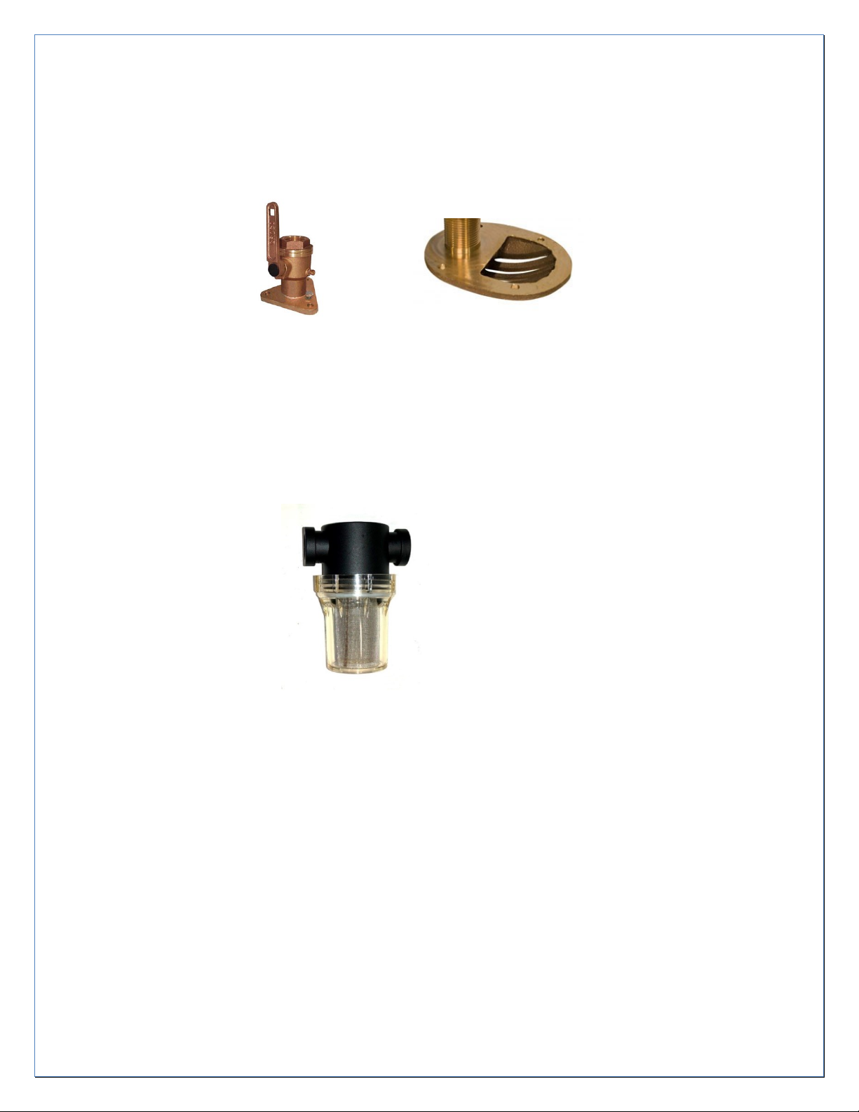
FILTER STATUS GAUGE:
Figure 8: Pre-Filter Status Gauge
The Pre-Filter is equipped with a “Status Gauge” to indicate when replacement is required….it is
connected using ¼” tubing from both inlet and outlet of filter. Note flow direction through
Status Gauge. Mount where it can easily be seen during operation. Double sticky foam or Alien
tape works good for mounting or can be fastened to a bulkhead
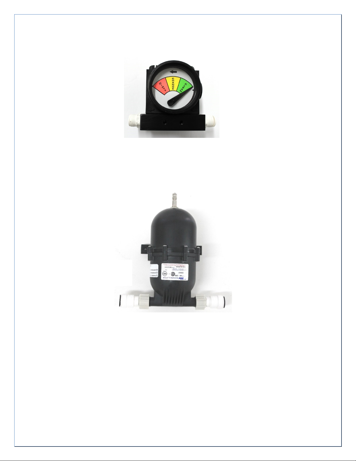
ACCUMULATOR TANK:
Figure 9: Accumulator Tank
The Accumulator Tank must be pressurized to 60 psi before use. It is mounted as close to the
Clark Pump as possible. Mount so the Schrader Valve (bicycle tire valve) is accessible to check
pressure. It is used to smooth out the feed flow to the Clark Pump 3G when the pump “shifts”
direction internally. Without it the Feed/Boost Pump might cycle off and on during a shift with
the pressure switch on the pump reacting to the pressure spike. Due to shipping restrictions the
Accumulator is not pressurized and requires being pressurized to 60 psi (4 atm). Use a bicycle
pump to fill to a higher pressure, and then use an accurate tire pressure gauge to set to 60 psi.
If the Clark Pump 3G shifts are affecting the Feed/Boost Pump, check the pressure while the
system is off and the Pressure Relief Valve open.
Water Flow is
Non-directional
16 V2
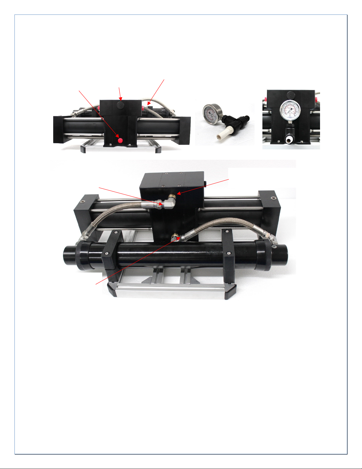
Pressure Relief Valve
CLARK PUMP 3G
Figure 10: Front View
Figure 11: Rear View
The Feed Pressure Gauge is shipped separately. Mount gauge to the inlet port as shown using the Teflon
Tape provided. Plastic Pipe Threads are only threaded in snug and will bottom out and leak if over
tightened. Locate the Clark Pump 3G and membrane assembly for easy access to the Pressure Relief
Valve and access to the pressure vessel for membrane replacement. The Clark Pump 3G can be mounted
in any orientation but if the Pressure Vessel is mounted vertical, the inlet of the pressure vessel needs to
be on the bottom to purge air from the top. The Clark Pump 3G has two brine discharge ports to choose
from. Both are plugged at the factory for shipping. Remove the plug for the one that best suits the
plumbing arrangement and leave the other side plugged. The Pressure Relief Valve is all plastic and is
only finger tightened. Do not over tighten. Leave the Pressure Relief Valve open ½ turn for the initial
commissioning. Before first start up, have the Black Feed Tube to the Clark Pump ready but not
connected.
High Pressure inlet
From Pressure Vessel
Feed Inlet with
shipping plug
High Pressure Outlet
To Pressure Vessel
Brine Out Ports, Left and Right
Usually only one is used
High Pressure Fittings
Swivel 360°
Inlet Pressure Gauge assembly

17 V2
PRESSURE VESSEL AND RO MEMBRANE ASSEMBLY:
Figure 12: Pressure Vessel and RO Membrane Assembly
The RO Membrane Element is shipped in the Pressure Vessel. The Clark Pump and Pressure
Vessel assembly have been flushed with a storage solution, drained and the inlet and outlet
of the Clark Pump and the membrane product outlet plugged to keep the membrane wet.
The Membrane should never be allowed to dry out. On first start up, the residual storage
solution needs to be purged before making water.
The Pressure Vessel with the RO Membrane inside it, is designed to be as compact as possible
for tight installations. It is specifically designed for low water flow drag for energy efficiency,
minimal metal exposed to salt water and ease of membrane replacement. If mounted with one
end up, place the Inlet end below the Outlet end with the flow going uphill to help purge air.
The stainless steel flare fittings threaded into the plastic endcaps have straight threads and O-
ring seals. They are only lightly tightened into the plastic after they bottom out. Do not over
tighten! If there is a leak between the fitting and the endcap, there is a problem with the O-ring
seal. Tightening will not help.
The Product Outlet End Cap can be positioned at either end as desired. See Membrane
Replacement for end cap removal and reinstallation. The Product Outlet Fitting is a 1/4” Push
to Fit for the product tubing. There is a 1/4” plastic plug in the product port for shipping.
Remove it just before connecting the product tube during installation. Do not let a membrane
dry out.
The flow through a membrane is directional due to a seal placed on one end of the membrane
to make it the inlet end. The seal directs the flow through the membrane and stops any flow
around the outside. If the placement of this seal is somehow lost, remove one end of the
Pressure Vessel. Grab and shake the end of the membrane. If it wobbles around easily the seal
is at the other end. If it hardly moves the seal is at that end.

18 V2
CONTROL PANEL:
The SolarMaax 10 is equipped with a basic electronic control system which has a manual override.
The manual override allows for emergency operation of the system in event of an electronic failure.
The Operator Control Panel (OCP) communicates with the Pump Control Module (PCM) to control the
Feed Pump and Auto Flush Mode as required.
Figure 13: Owner Control Panel (OCP)
OCP has the following features / functions, interfacing with the Pump Control.
A. ON / OFF button with LED to indicate motor status
B. Manual 3-way valve to direct product flow to tank or testing port
C. Analog flow gauge
D. Product test port
E. Auto & Manual Flush control with indicator LED
The Control Panel is surface mounted using the supplied standoffs. Place it so it is easily accessed, and
the test port tube can be led to drain somewhere safe. For ease of service, the Panel and the 3 Way
Service Valves should be located close to each other so all three Service Tubes can reach the Service Pail.

19 V2
3-WAY SERVICE VALVES:
Figure 14: 3-way Service Valves
Two 3-way service valves are provided for access to the seawater Feed Line and Brine Discharge
Line. They are used to facilitate membrane storage and cleaning procedures. They should be
place so their alternant Service Tubes can reach a Service Pail at the same time.
A. The Intake Service Valve can be placed anywhere between the strainer and the Feed
Pump. It can be hard mounted directly to the sea strainer with the fittings supplied
B. The Discharge Service Valve is placed anywhere in the Brine Discharge Line including
mounting directly on the Clark Pump 3G brine outlet port.
Note the common port; the valve will always introduce a 90 degree turn in the water flow.
There is no straight through position.
DISCHARGE THROUGH HULL:
Figure 15: Brine Discharge Through Hull Fittings (Owner Suplied)
The red Brine Discharge Tube from the 3 way Brine Service Valve is led to a dedicated Owner
Supplied through 1/2” hull fitting just above the waterline. It is possible to tee it into an existing
drain above the waterline but there is a good chance it will cause gurgling noise and flood the
boat if the drain through hull valve is closed. Sharing a discharge is highly discouraged for those
reasons.
Common Port

20 V2
TANK FILL SELECTOR VALVE:
Figure 16: Optional Tank fill Selector Valve
If more than one tank needs to be filled, a Product Water 3-way Valve can be installed in the
product line from the panel. A Product Water 3-way Valve is a specific type of valve that cannot
block the Product flow in any valve position (non-dead heading)
Caution: Do not use any type of selector valve that can block the flow any way, even
momentarily, or damage to the system will happen. The valve can be mounted in a panel or
fastened to a wall by drilling out the mounting holes.
TDS TESTER AND TESTING PRODUCT WATER QUALITY:
Figure 17: Hand Held TDS Tester
A good RO membrane will produce product water that is well below the upper limit of 500
parts per million (ppm) of Total Dissolved Solids (TDS) of which is mostly salt in seawater. On
startup, the first flow out of a membrane that’s been operating in salt water will have a high
TDS reading (taste salty) because of osmosis inside the membrane while it’s been
depressurized. This first low-quality water will quickly be flushed out so there is a waiting
period after start up to test the product. The Held Salinity/TDS Meter can accurately determine
the quality of the product water and be compared to an actual “taste” test. For most people, a
simple taste test is sufficient to determine if the water is drinkable. Most people can start to
taste the salt when the TDS is getting close to the upper limit of 500 ppm, but some cannot
taste it even if it’s well above 500 ppm and would not be considered good. To “TEST” the
product do the following steps on the next page.
Product Flow Inlet
To Tank 1
To Tank 2
This manual suits for next models
1
Table of contents
Other ElectroMaax Water Filtration System manuals


