IT IE
Cod. 1.045394 - Rev. ST.005370/001
KIT FILTRO CICLONICO MAGNETICO
PER TRIO
COD. 3.031810
TRIO MAGNETIC CYCLONE
FILTER KIT
CODE 3.031810
AVVERTENZE GENERALI.
Tutti i prodotti sono protetti con idoneo imballaggio da trasporto.
Il materiale deve essere immagazzinato in ambienti asciutti ed
al riparo dalle intemperie. Il presente foglio istruzioni contiene
informazioni tecniche relative all’installazione del kit. Per quanto
concerne le altre tematiche correlate all’installazione del kit stesso
(a titolo esemplicativo: sicurezza sui luoghi di lavoro, salvaguardia
dell’ambiente, prevenzioni degli infortuni), è necessario rispettare i
dettami della normativa vigente ed i principi della buona tecnica.
L’installazione o il montaggio improprio dell’apparecchio e/o dei
componenti, accessori, kit e dispositivi potrebbe dare luogo a proble-
matiche non prevedibili a priori nei confronti di persone, animali,
cose. Leggere attentamente le istruzioni a corredo del prodotto per
una corretta installazione dello stesso.
L’installazione e la manutenzione devono essere eettuate in ottem-
peranza alle normative vigenti, secondo le istruzioni del costruttore e
da parte di personale abilitato nonché professionalmente qualicato,
intendendo per tale quello avente specica competenza tecnica nel
settore degli impianti, come previsto dalla Legge.
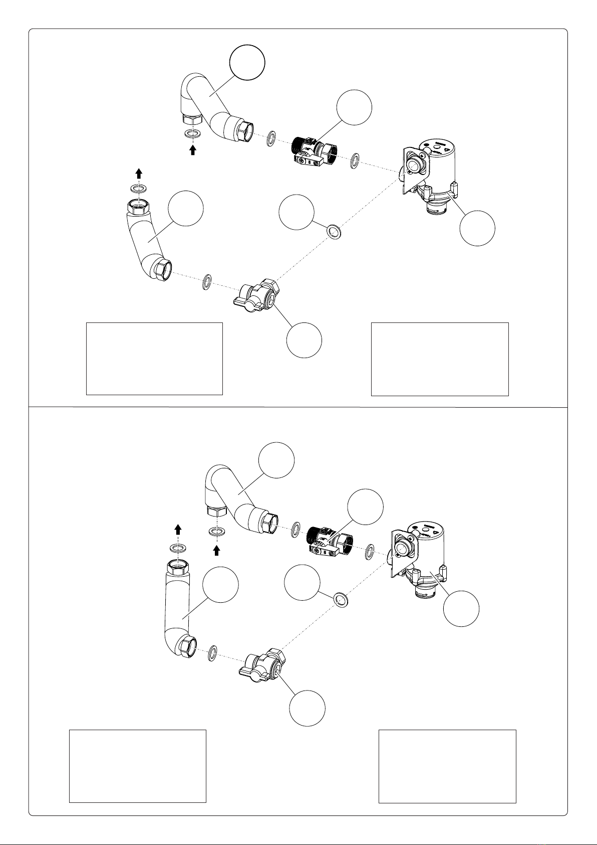
DESCRIZIONE DEL PRODOTTO.
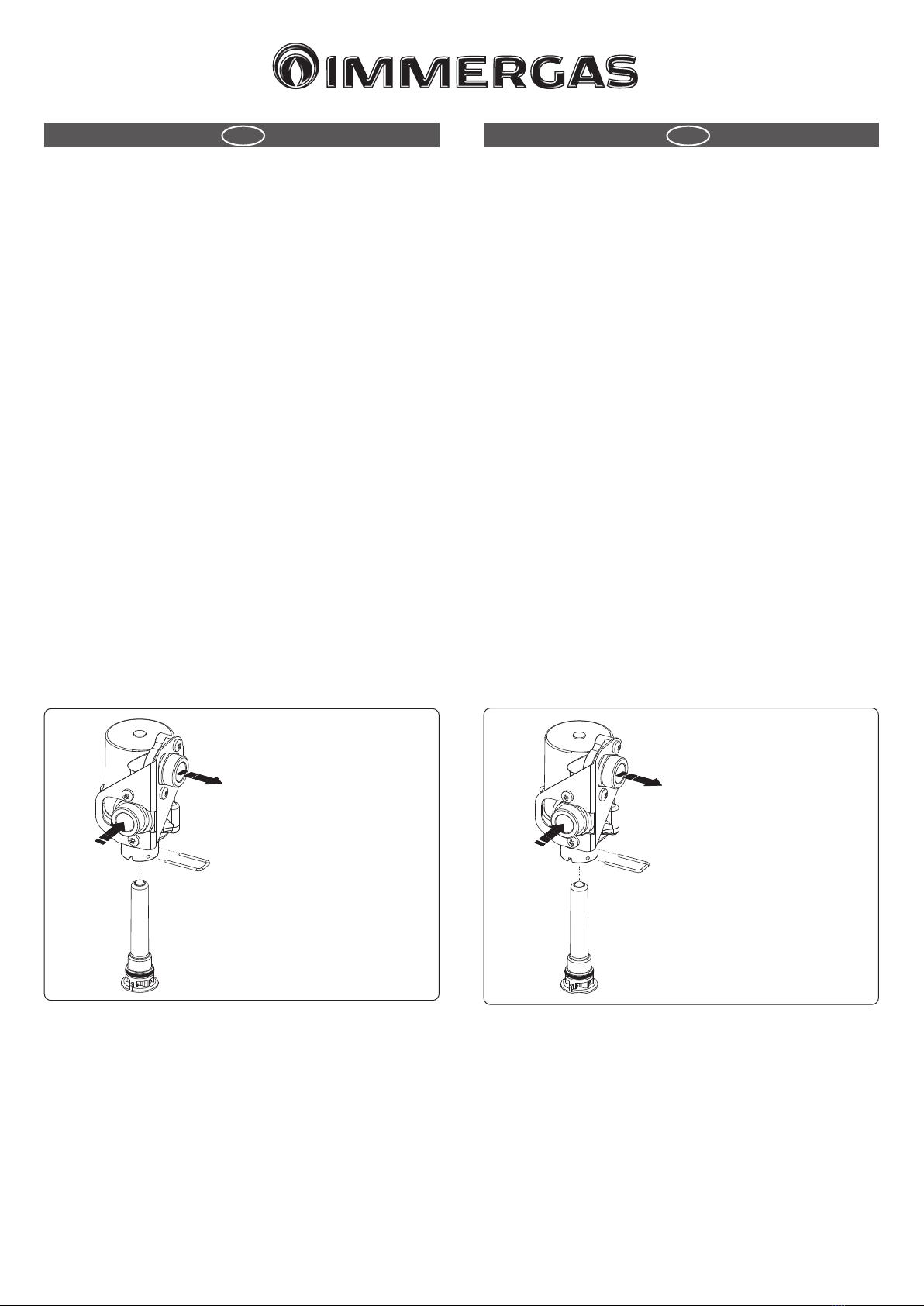
Il ltro ciclonico magnetico permette di intercettare i residui
ferrosi presenti nell'acqua di impianto. Grazie ad i due rubinetti
presenti nel kit è possibile eettuare una facile manutenzione
pulendo il ltro senza bisogno di dover svuotare il circuito.
Fig. 1
R
Legenda:
R -Ritorno impianto
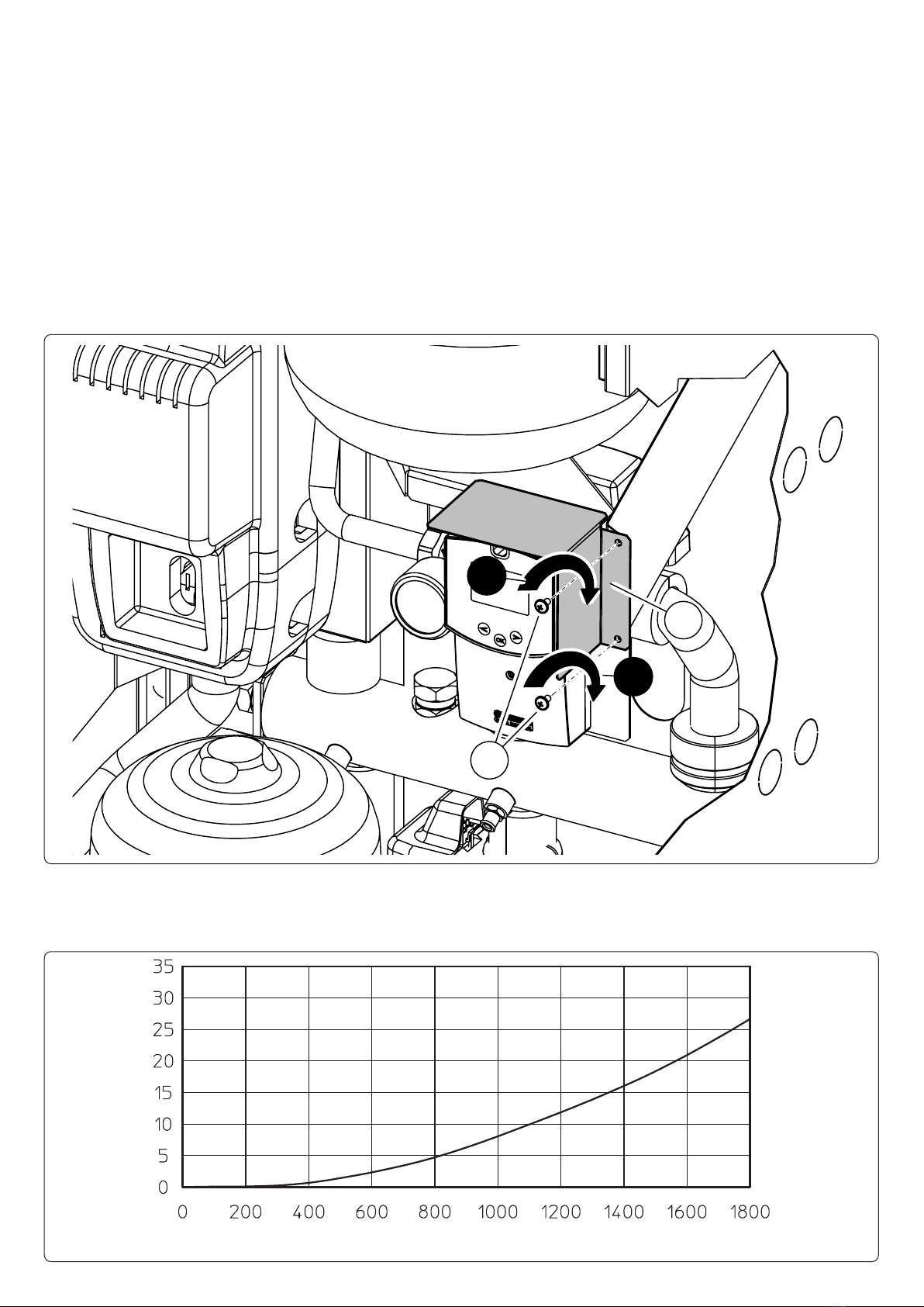
AVVERTENZE.
I magneti resistono no alla temperatura massima di 100 °C, si
consiglia quindi di non superare una temperatura compresa tra
90 - 95 °C.
Campi magnetici:
- Tenere il magnete a debita distanza da tutti gli oggetti e apparec-
chiature che potrebbero essere danneggiati dai campi magnetici
stessi.
- Il campo magnetico può inuenzare il funzionamento di pace-
maker e debrillatori interni, per sicurezza tenere il magnete a
una distanza di sicurezza.
GENERAL WARNINGS.
All products are protected with suitable transport packaging.
e material must be stored in dry environments and protected
against weathering.
is instruction manual provides technical information for installing
the kit. As for the other issues related to kit installation (e.g. safety
in the work site, environment protection, injury prevention), it is
necessary to comply with the provisions specied in the regulations
in force and principles of good practice.
Improper installation or assembly of the appliance and/or compo-
nents, accessories, kit and devices can cause unexpected problems
to people, animals and objects. Read the instructions provided with
the product carefully to ensure a proper installation.
Installation and maintenance must be performed in compliance with
the regulations in force, according to the manufacturer's instructions
and by authorised professionally qualied sta, intending sta with
specic technical skills in the plant sector, as envisioned by the Law.
DESCRIPTION OF THE PRODUCT.
e magnetic cyclone lter is able to detect the ferrous residues
present in the system's water. anks to the two taps in the kit,
it facilitates maintenance by cleaning the lter without having to
empty the circuit.
Fig. 1
R
Key:
R -System return
WARNINGS.
e magnets can withstand a maximum temperature of 100 °C, so
it is recommended not to exceed a temperature between 90 - 95 °C.
Magnetic elds:
- Keep the magnet at a safe distance from all objects and equip-
ment that could be damaged by the magnetic elds.
- e magnetic eld can aect the operation of pacemakers and
internal debrillators, therefore keep the magnet at a safe dis-
tance.