SPAN selectors. If the coupling is misaligned, the
selectors will double detent or switch withagrinding
noise. Refer to Knob Removal and Installation
instructions in the Maintenancesection of the manual
for realignment.
VARIABLE (FREQSPANIDIV)
Push-push type switch and control. When it is out of
its
CAL detent, the control provides variable frequency span
between each step of the FREQ SPANIDIV selector. The
control must be in the CAL detent for calibrated
FRf
Cl
SPAN displays.
RESOLU'TION
Selects five calibrated resolution bandwidths, from
300
Hz to
3
MHz (within
20%).
in decade steps. Shape
factor of rile response, over the
60
dB to
6
dB amplitude
levels,
is
4:l
or better.
PULLTO UNLOCK
A concentric sleeve around the VARIABLE control that
unlocks the RESOLUTION from the FREQ SPANIDIV
selector. and allows each selector to be independently
set.
LOG
10
dB/DIV
Selects a display mode with a calibrated dynamic range
of 70 dB (to the 7th graticule line from the top) at
10
dBIDIV. The bottom graticule division
is
not calibrated.
LOG
2
dB/DIV
When this button
is
depressed, the dynamic range of the
display
is
acalibrated
14
dB at
2
dB/DIV.
LIN
Selects a linear display, that corresponds to the linear
calibration on the left side of the graticule overlay.
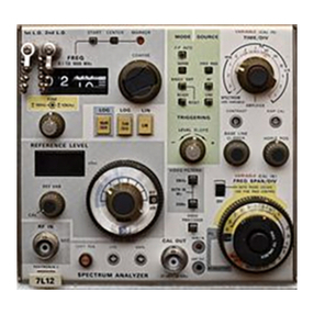
REFERENCE LEVEL, RF Attenuation, and MAXimum
Power Level Indicators and Selectors
Concentric controls that are connected in an electro-
mechanical differential arrangement which select input
altenuation and instrument gain.
The Input attenuation (from
0
dB to
60
dB) and Gain
(0
dB to
70
dB) are selected in
10
dB steps. An electro-
mechanical arrangement and readout windows establish and
indicate to the user, MAXirr~umpower input level (indBm),
RF attenuation (in dB), and the REFERENCE LEVEL (in
dBm) of the top graticule line. REFERENCE LEVEL
is
also displayed on CRT's of oscilloscopes with readout
feature.
NOTE
A
blue tint borders the lOdB/DIV display switch,
and four positions of the Gain selector. This
is
to
correlate REFERENCE LEVEL readout to Gain
switch settings that are applicable in the 10dB/DIV
display mode. Readings outside the blue sector are
erroneous because thegain is electrically locked out.
'The CRT readout will display the
<
symbol to
signify the readings are erroneous. The dynamic
window of the diqlay will not exceed
--.
130dBm
(REFERENCE LEVEL of 6OdBm plus 70dB
dynamic range of the 10dB/DIV display). In the
2
dB/DIV display mode, the full 70dB range of the
Gain selector is usable. Switching the Gain fully CW
with the RF attenuator at 0 dB,produces an accurate
-
100dBm reference level. The dynamic range of the
display is now
-
I14dBm (-100 dBm plus 14dB
graticule window, to the 7thgraticule line).
VARIABLE (Gain)Control
Provides at least
10
dB of gain variation. The REFER-
ENCE LEVEL readout on the CR'I' changes to the
<
symbol to indicate an uncalibrated condition when
it
is
out
of its CAL detent. The readout of the REFERENCE
LEVEL window on the
7L12
is only applicable when this
control is in
its
CALdetent.
FREQUENCY MHz
Dial reads out the START-CENTER or MARKER
frequency of the display. Frequency and dial readout are
tuned by the COARSEcontrol.
Depressing the START push-button, selects the start of
the display or left (zero)graticule line as the frequency that
is
indicated by the dial readout. Depressing the CENTER
push-button selects the center of the display as the
frequency indicated in the readout window. When the
FREQ SPANIDIV is switched to MAX SPAN position, the
MARKER indicator is lighted and a notch on the baseline
of the display indicates the center of that portion of the
span that will be displayed when the FREQ SPAN
is
reduced.
FINE Frequency Controls
Two concentric controls that provide fine tuning adjust-
ment during phase lock operation or at spans which are
0.1
MHzIDiv or less.