Orbit Merret OM 502 User manual

OM 502
5 DIGIT PROGRAMMABLE INSTRUMENT
DC VOLTMETER/AMMETER
PROCESS MONITOR
INTEGRATOR
LINEARIZATOR
DISPLAYS FOR LINEAR POTENTIOMETERS
DISPLAY INSTRUMENT FOR TENSIOMETERS
DISPLAYS FOR LVDT SENSORS
USER MANUAL
148.9~C-263mm
453mV
Outstanding Measurement Value

2| INSTRUCTIONS FOR USE OM 502
TECHNICAL DATA
Measuring instruments of the OM 502 series conform to the European regulation 2014/30/EU and 2014/35/EU
The instruments are up to the following European standards
EN 61010-1 Electrical safety
EN 61326-1 Electronic measuring, control and laboratory devices
- Requirements for EMC “Industrial use”
IEC 980: 1993, Par. 6 Seismic resistance
The recorders are applicable for unlimited use in agricultural and industrial areas.
ORBIT MERRET, spol. sr.o.
Vodňanská 675/30
19800 Praha 9
Czech republic
Tel: +420 - 281040200
Fax: +420 - 281040299
www.orbit.merret.eu
SAFETY INSTRUCTIONS
Please read carefully the enclosed safety instructions and observe them!
Installation, all operational interventions, maintenance and service must be performed by a qualified per-
sonnel and in accordance with the attached information and safety regulations. The manufacturer is not
liable for damage caused by improper installation, configuration, maintenance, and service.
The recorder must be installed according to the respective application. Incorrect installation can cause a
malfunction, which can result in damage or accident.
The recorder uses dangerous voltages that can cause a fatal accident. Before you start solving problems
(e.g. in case of failure or disassembly), the device must be disconnected from the power supply. For safety
information the EN 61010-1 + A2 standard must be observed.
When removing or inserting a card, observe the safety instructions and follow the recommended procedure.
During any intervention the recorder must be disconnected from the power supply.
Do not attempt to repair or modify the device. A defective recorder must be sent for repair to the manufacturer.
These devices should be safeguarded by isolated or common fuses (breakers)!
The recorder is not designed for installation in potentially explosive surroundings (Ex). Use it only outside
potentially explosive surroundings

INSTRUCTIONS FOR USE OM 502 | 3
1.CONTENTS
1. CONTENTS . . . . . . . . . . . . . . . . . . . . . . . . . . . . . . . . 3
2. INSTRUMENT DESCRIPTION . . . . . . . . . . . . . . . . . . . 4
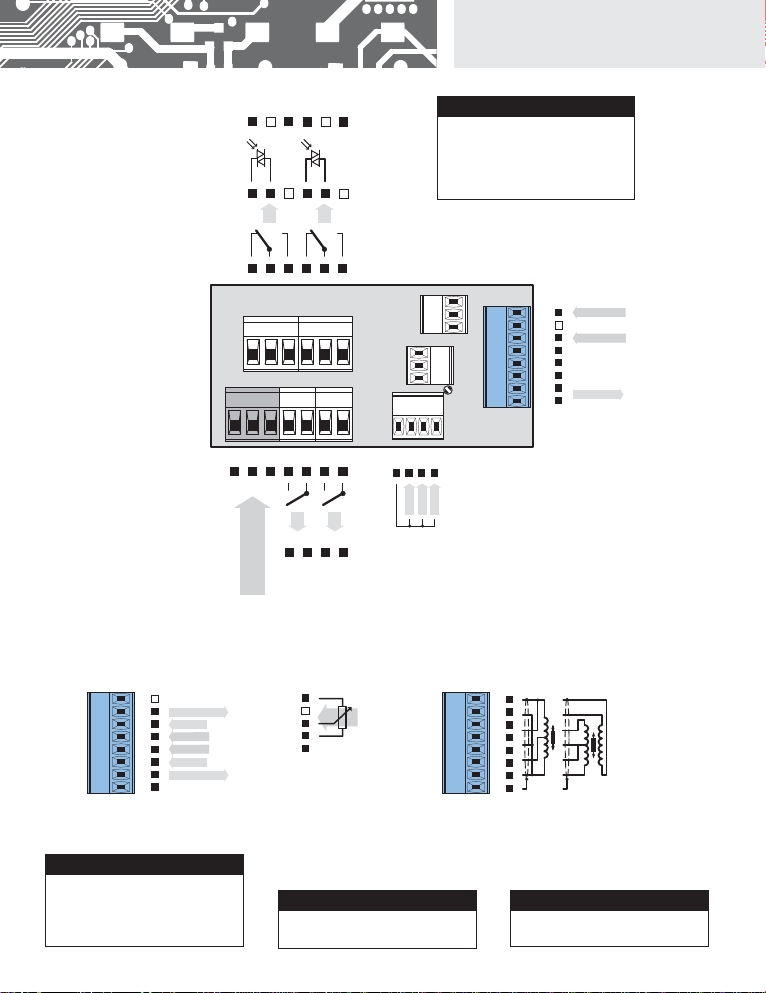
3. INSTRUMENT CONNECTION. . . . . . . . . . . . . . . . . . . . 6
Measuring ranges . . . . . . . . . . . . . . . . . . . . . . . . . . . . . 6
Termination of RS 485 communication line . . . . . . . . 6
Instrument connection . . . . . . . . . . . . . . . . . . . . . . . . . 7
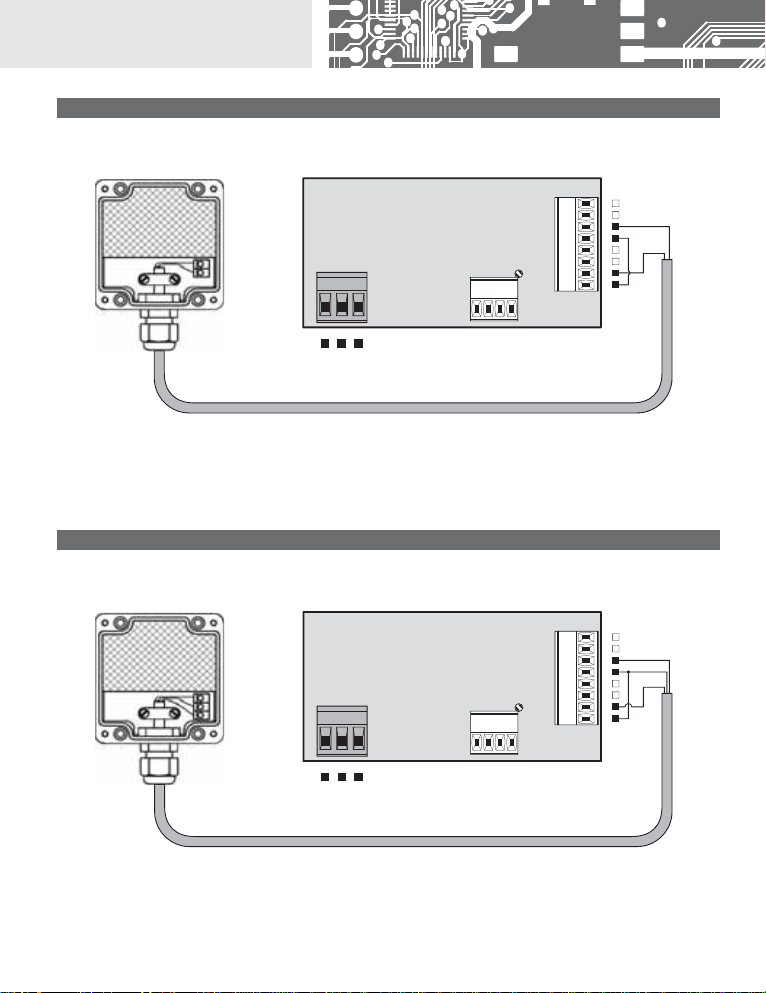
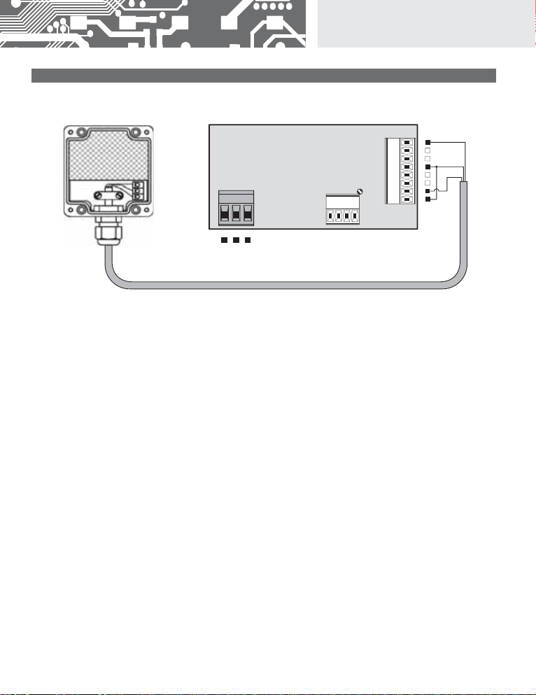
Recommended connection of sensors. . . . . . . . . . . . 8
4. INSTRUMENT SETTING . . . . . . . . . . . . . . . . . . . . . . 10
Symbols used in the instructions . . . . . . . . . . . . . . . 12
Setting the DP and the (-) sign . . . . . . . . . . . . . . . . . 12
Control keys function . . . . . . . . . . . . . . . . . . . . . . . . . 13
Setting/permitting items into “USER” menu . . . . . . . 13
5. SETTING “LIGHT” MENU . . . . . . . . . . . . . . . . . . . . . .14
5.0 Description “LIGHT” menu . . . . . . . . . . . . . . . . . . . 14
Setting input - Type “DC” . . . . . . . . . . . . . . . . . . . . . . 18
Setting input - Type “PM” . . . . . . . . . . . . . . . . . . . . . . 20
Setting input - Type “I”. . . . . . . . . . . . . . . . . . . . . . . . .22
Setting input - Type “LX” . . . . . . . . . . . . . . . . . . . . . . . 24
Setting input - Type “DU” . . . . . . . . . . . . . . . . . . . . . .26
Setting input - Type “T” . . . . . . . . . . . . . . . . . . . . . . . . 28
Setting input - Type “LVDT” . . . . . . . . . . . . . . . . . . . .30
Setting Limits . . . . . . . . . . . . . . . . . . . . . . . . . . . . . . . .32
Setting analog output . . . . . . . . . . . . . . . . . . . . . . . . .34
Selection of programming menu „LIGHT“/„PROFI“ . .36
Restoration of manufacture setting . . . . . . . . . . . . .36
Automatic calibration - input range (only “DU”) . . . . 37
Selection of instrument menu language version . .38
Setting new access password . . . . . . . . . . . . . . . . .38
Instrument identification . . . . . . . . . . . . . . . . . . . . . . . 39
6. SETTING “PROFI” MENU . . . . . . . . . . . . . . . . . . . . . 40
6.0 Description of “PROFI” menu . . . . . . . . . . . . . . . . . . 40
6.1 “PROFI” menu - INPUTS
6.1.1 Resetting internal values . . . . . . . . . . . . . . . .42
6.1.2 Setting measuring type, range, mode, rate. . 43
6.1.3 Setting the Real Time . . . . . . . . . . . . . . . . . . . 45
6.1.4 External input function selection . . . . . . . . . . 48
6.1.5 Optional accessory functions of the keys . . 49
6.2 “PROFI” menu - CHANNEL
6.2.1 Setting measuring parameters
(projection, filters, decimal point, description) . . . . . 57
6.2.2 Setting mathematic functions . . . . . . . . . . . . 57
6.2.3 Setting integrator parameters . . . . . . . . . . . .60
6.2.4 Selection of evaluation of min/max. value . . 64
6.3 “PROFI” menu - OUTPUT
6.3.1 Setting data logging. . . . . . . . . . . . . . . . . . . . . 66
6.3.2 Setting Limits . . . . . . . . . . . . . . . . . . . . . . . . . .68
6.3.3 Setting data output . . . . . . . . . . . . . . . . . . . . . 71
6.3.4 Setting analog output . . . . . . . . . . . . . . . . . . . 72
6.3.5 Selection of display projection . . . . . . . . . . . . 74
6.4 “PROFI” menu - SERVICE
6.4.1 Selection of programming menu
„LIGHT“/„PROFI“ . . . . . . . . . . . . . . . . . . . . . . . . 76
6.4.2 Restoration manufacture setting . . . . . . . . . . 77
6.4.3 Automatic calibration - input range . . . . . . . . 78
6.4.4 Selection of instrument menu
language version . . . . . . . . . . . . . . . . . . . . . . . 79
6.4.5 Setting new access password . . . . . . . . . . . 79
6.4.6 Instrument identification . . . . . . . . . . . . . . . . . 79
7. SETTING ITEMS INTO “USER” MENU . . . . . . . . . . . . 80
8. DATA PROTOCOL . . . . . . . . . . . . . . . . . . . . . . . . . . . 82
9. ERROR STATEMENTS . . . . . . . . . . . . . . . . . . . . . . . . 84
10.TABLE OF SYMBOLS . . . . . . . . . . . . . . . . . . . . . . . . 85
11. TECHNICAL DATA . . . . . . . . . . . . . . . . . . . . . . . . . . 86
12. INSTRUMENT DIMENSIONS AND INSTALATION . . . . 88
13. CERTIFICATE OF GUARANTEE . . . . . . . . . . . . . . . . ..89

4| INSTRUCTIONS FOR USE OM 502
2. INSTRUMENT DESCRIPTION
2.1 DESCRIPTION
The OM 502 model series are 5 digit panel programmable instruments.
The instrument is based on 8-bit microcontroller with hight-rate 24-bit sigma-delta converter, which secures high accuracy,
stability and easy operation of the instrument.
TYPES AND RANGES
DC DC Voltmeter/Ammeter
±999,99 mV; ±999,99 mV; ±9,9999 V; ±99,999 V; ±300,00 V
±999,99 A; ±9,9999 mA; ±99,999 mA; ±999,99 mA; ±5,0000 A
PM Process monitor
0…5 mA/0…20 mA/4…20 mA/±2 V/±5 V/±10 V
I Integrator
0…5 mA/0 …20 mA/4…20 mA/±2 V/±5 V/±10 V
L Linearizator
0…5 mA/0…20 mA/4…20 mA/±2 V/±5 V/±10 V
DU Display unit for linear potentiometers
Linear potentiometer (min. 500 )
T Weighing indicator
1…4 / 2…8 / 4…16 mV/V
LVDT Display unit for LVDT sensor
1 / 3 / 5 VAC, 2,5 / 5 / 10 kHz
PROGRAMMABLE PROJECTION, FUNCTION
Measuring range: adjustable (PM, I, LX) or as per order (DC, T)
Setting: manual, optional display projection may be set for both limit values of the input signal,
e.g. input 0…20 mA> 0…8500,0
Projection: ±99999 (-99999…999999)
Integration (I): with time base 1 s, projection of integrated and current value
Weighing function (T): manual or automatic calibration, signalization of stabilized equilibrium, zero stabilization,
automatic zero monitoring, defined number of sections on the scale
Projection (T): ±99999 (Mode - Standard)
selection of size of the section - 0,001/0,002/0,005/0,01/0,02/0,05/0,1/0,2/0,5/1/2/5/
10/20/50/100 (Mode - WEIGHT)
LINEARIZATION
Linearization: by linear interpolation in 50 points (solely via OM Link)
Linearization (LX): linear interpolation in 256 points and 16 tables
DIGITAL FILTERS
Floating average: from 2…30 measurements
Exponen.average: from 2…100 measurements
Rounding: setting the projection step for display
MATHEMATIC FUCTIONS
Min/max. value: registration of min./max. value reached during measurement
Tare: designed to reset display upon non-zero input signal
Fixed tare: fixed preset tare
Peak value: the display shows only max. or min. value
Mat. operations: polynome, 1/x, logarithm, exponential, power, root, sin x

INSTRUCTIONS FOR USE OM 502 | 5
2.INSTRUMENT DESCRIPTION
EXTERNAL CONTROL
Lock: control keys blocking
Hold: display/instrument blocking
Tare: tare activation/resetting tare to zero
Resetting MM: resetting min/max value
Memory: data storage into instrument memory
2.2 OPERATION
The instrument is set and controlled by five control keys located on the front panel. All programmable settings of the instrument
are performed in three adjusting modes:
LIGHT Simple programming menu
- contains solely items necessary for instrument setting and is protected by optional number code
PROFI Complete programming menu
- contains complete instrument menu and is protected by optional number code
USER User programming menu
- may contain arbitrary items selected from the programming menu (LIGHT/PROFI), which determine
the right (see or change)
- acces without password
All programmable parameters are stored in the EEPROM memory (they hold even after the instrument is switched off).
Complete instrument operation and setting may be performed via OM Link communication interface, which is a
standard equipment of all instruments.
The operation program is freely accessible (www.orbit.merret.eu) and the only requirement is the purchase of OML cable to
connect the instrument to PC. It is manufactured in version RS 232 and USB and is compatible with all ORBIT MERRET instru-
ments. Another option for connection is with the aid of data output RS 232 or RS 485 (without the need of the OML cable).
The program OM LINK in „Basic“ version will enable you to connect one instrument with the option of visualization and archiving
in PC. The OM Link „Standard“ version has no limitation of the number of instruments connected.
2.3 OPTIONS
Excitation
is suitable for supplying power to sensors and transmitters. It has a galvanic separation.
Comparators
are assigned to monitor one, two, three or four limit values with relay output. The user may select limits regime:
LIMIT/DOSING/FROM-TO. The limits have adjustable hysteresis within the full range of the display as well as selectable delay
of the switch-on in the range of 0…99,9 s. Reaching the preset limits is signalled by LED and simultaneously by the switch-on
of the relevant relay.
Data outputs
are for their rate and accuracy suitable for transmission of the measured data for further projection or directly into
the control systems. We offer an isolated RS232 and RS485 with the ASCII, MESSBUS, MODBUS - RTU or PROFIBUS protocol.
Analog outputs
will find their place in applications where further evaluating or processing of measured data is required in
external devices. We offer universal analog output with the option of selection of the type of output - voltage/current. The value
of analog output corresponds with the displayed data and its type and range are selectable in Menu.
Measured data record
is an internal time control of data collection. It is suitable where it is necessary to register measured
values. Two modes may be used. FAST is designed for fast storage (100 records/s) of all measured values up to 8 000 records.
Second mode is RTC, where data record is governed by Real Time with data storage in a selected time segment and cycle. Up to
266 000 values may be stored in the instrument memory. Data transmis sion into PC via serial interface RS232/485 and OM Link.

6| INSTRUCTIONS FOR USE OM 502
3. INSTRUMENT CONNECTION
The instrument supply leads should not be in proximity of the incoming low-potential signals.
Contactors, motors with larger input power should not be in proximity of the instrument.
The leads into the instrument input (measured quantity) should be in sufficient distance from all power leads and appliances.
Provided this cannot be secured it is necessary to use shielded leads with connection to ground (bracket E).
The instruments are tested in compliance with standards for use in industrial area, yet we recommend to abide by the above
mentioned principles.
MEASURING RANGES
TYPE INPUTS I INPUTS U
DC ±999,99 A; ±9,9999 mA; ±99,999 mA;
±999,99 mA; ±5,0000 A
±999,99 mV; ±999,99 mV; ±9,9999 V;
±99,999 V; ±300,00 V
PM 0…5/20 mA/4…20 mA ±2/±5/±10 V
I0…5/20 mA/4…20 mA ±2/±5/±10 V
LX 0…5/20 mA/4…20 mA ±2/±5/±10 V
DU Linear potentiometer (min. 500 )
T1…4 / 2…8 / 4…16 mV/V
Termination of RS 485 communication line
Full Significance Default Recomendation
1-2 connect L+ to (+) source terminalconnected
3-4 termination of line 120 Ohm disconnected connect at the end of line
5-6 connect L- to (-) source terminalconnected do not disconnect
RS 485 line should have a linear structure - wires (ideally shielded and twisted)
should lead from one device to another.
X3 - Termination of commuication line RS 485
X3
153

INSTRUCTIONS FOR USE OM 502 | 7
3.INSTRUMENT CONNECTION
-
-
-
+
+
+
+
-
54
8910
L
NPOWER SUPPLY
E
123
11 12 13
567 14 15 16 17
IV V VI
III II I
L4
L3
L2
L1
EXT. 1
EXT. 3
EXT. 2
RxD/L+
TxD/L-
GND
AO - I
AO - U
GND
ABC D E FGH
Shielding
Excitation
INPUT I
INPUT U
+
+
+
-
-GND
Shielding
DMS supply
INPUT
INPUT
DMS supply
Sense
Sense
OM 502DUOM 502T
OM 502DC, PM, I, L
X
Shielding
b
e
ABC D E FGH
+
-
-GND
E 1
C 2
E 2
C 1
Open collector
SSR
Open collector
C 3
E 4
C 4
E 3
3W 5W
ABC D E FGH
OM 502LVDT
Excitation value may be set by trimmer above
the terminal block no. 17
!
Signal „SENSE“ measures supply voltage on
tensionmeter upon 6-wire connection, for
4-wire connection join brackets B+C andF+G
directly on the instrument. Whenusing the
instrument in highly disturbing environemnt
we recommend using 4-wire connection.
!
Grounding on terminal block 3 has to be
connected at all times
!
Terminal block “Shielding” is designed for
connecting shielding of the supply lead (con-
nected only on the side of the instrument).
The “Shielding” and “GND” terminal blocks
MUST NOT be connected
!

8| INSTRUCTIONS FOR USE OM 502
3. INSTRUMENT CONNECTION
Example connection of a 2-wire sensor with current signal output powered by instrument’s excitation
Example connection of a 3-wire sensor with current signal output powered by instrument’s excitation
+
-
L
N
E
123 14 15 16 17
ABC D E FGH
+
+
-
-
(+)
(-)
INPUT - I
Excitation
Sensor (-)
Sensor (+)
+
-
L
N
E
123 14 15 16 17
ABC D E FGH
+
+
-
-
INPUT - I
Excitation
Output (+)
Supply (+)
Supply (+)
Output (+)
GND (-)
GND

INSTRUCTIONS FOR USE OM 502 | 9
INSTRUMENT CONNECTION 3.
Example connection of 3-wire sensor with voltage signal output powered by instrument’s excitation
+
-
L
N
E
123 14 15 16 17
ABC D E FGH
+
+
-
-
INPUT - U
Excitation
Output (+)
Supply (+)
Supply (+)
Output (+)
GND (-)
GND

10 | INSTRUCTIONS FOR USE OM 502
4. INSTRUMENT SETTING
SETTING
PROFI
For expert users
Complete instrument menu
Access is password protected
Possibility to arrange items of the USER MENU
Tree menu structure
SETTING
LIGHT
For trained users
Only items necessary for instrument setting
Access is password protected
Possibility to arrange items of the USER MENU
Linear menu structure
SETTING
USER
For user operation
Menu items are set by the user (Profi/Light) as per request
Access is not password protected
Optional menu structure either tree (PROFI) or linear (LIGHT)

INSTRUCTIONS FOR USE OM 502 | 11
INSTRUMENT SETTING 4.
4.1 SETTING
The instrument is set and controlled by five control keys located on the front panel. All programmable settings of the instrument
are performed in three adjusting modes:
LIGHT Simple programming menu
- contains solely items necessary for instrument setting and is protected by optional number code
PROFI Complete programming menu
- contains complete instrument menu and is protected by optional number code
USER User programming menu
- may contain arbitrary items selected from the programming menu (LIGHT/PROFI), which determine
the right (see or change)
- acces without password
Complete instrument operation and setting may be performed via OM Link communication interface, which is a standard equip-
ment of all instruments.
The operation program is freely accessible (www.orbit.merret.eu) and the only requirement is the purchase of OML cable to
connect the instrument to PC. It is manufactured in version RS 232 and USB and is compatible with all ORBIT MERRET instru-
ments. Another option for connection is with the aid of data output RS 232 or RS 485 (without the need of the OML cable).
Scheme of processing the measured signal
CHAN. A
FILTER
MAT.FCE.
Relays
Analog
Memory
Min/Max
Data
Linearization
Input
Linearization Display

12 | INSTRUCTIONS FOR USE OM 502
4. INSTRUMENT SETTING
Setting and controlling the instrument is performed by means of 5 control keys located on the front panel. With the aid of these
keys it is possble to browse through the operation menu and to select and set required values.
Symbols used in the instructions
DC PM
DU ILX TIndicates the setting for given type of instrument
DEF values preset from manufacture
42symbol indicates a flashing light (symbol)
MIN inverted triangle indicates the item that can be placed in USER menu
INTEG.broken line indicates a dynamic item, i.e. it is displayed only in particular selection/version
after pressing the key the set value will not be stored
after pressing the key the set value will be stored
30
continues on page 30
Setting the decimal point and the minus sign
DECIMAL POINT
Its selection in the menu, upon modification of the number to be adjusted it is performed by the control key with transition
beyond the highest decade, when the decimal point starts flashing . Positioning is performed by /.
THE MINUS SIGN
Setting the minus sign is performed by the key on higher decade. When editing the item substraction must be made from
the current number (e.g..: 013 > , on class 100 > -87)
ON the digit is lit
OFF the digit is not lit
OFF the digit is flashing
limits withrestriction
(hysteresis, delay)
12 T34M
w185.42 M Min/max. value
Netto (regime "WEIGHT")
T Tare
Status indication
wequilibrium position
zsteady zero
(regime "WEIGHT")
Ralay status Function
Measured value
the last two places may display
measuring units

INSTRUCTIONS FOR USE OM 502 | 13
INSTRUMENT SETTING 6.
Control keys functions
Setting items into „USER“ menu
• inLIGHT or PROFI menu
• no items permitted in USER menu from manufacture
• on items marked by inverted triangle
NO item will not be displayed in USER menu
YES item will be displayed inUSER menu with the option of setting
SHOW item will be solely displayed in USER menu
KEY MEASUREMENT MENU SETTING NUMBERS/SELECTION
access into USER menu exit menu quit editing
programmable key function back to previous level move to higher decade
programmable key function move to previous item move down
programmable key function move to next item move up
programmable key function confirm selection confirm setting/selection
+numeric value is set to zero
+access into LIGHT/PROFI menu
+direct access into PROFI menu
+configuration of an item for
“USER” menu
+determine the sequence of items in
“USER - LIGHT” menu
USER
--- +NO YES SHOW ---
return to item
legend is flashing - current setting is displayed

14 | INSTRUCTIONS FOR USE OM 502
5. SETTING LIGHT
SETTING
LIGHT
For trained users
Only items necessary for instrument setting
Access is password protected
Possibility to arrange items of the USER MENU
Linear menu structure
Upon delay exceeding 60 s the program-
ming mode is automatically discontinued
and the instrument itself restores the
measuring mode
!
Password “0”
Menu LIGHT
USER menu off
Setting the items DEF
Preset from manufacture

INSTRUCTIONS FOR USE OM 502 | 15
SETTING LIGHT 5.
Option - Analog output
TYP. A.O. MIN A.O. MAX A.O. 10000-20mA
Option - Comparators
Calibration - only for “DU”
New password
PAS.LI.0
C. MIN YES C. MAX YES
DU
Language selection
LANG.ENGL.
142.8 PASSW 0
+
Access password
TYPE
Return to manufacture calibration Return to manufacture setting
RE.CAL.YES RE.SET.
LIM. L.1 20 LIM. L.2 40 LIM. L.3 60 LIM. L.4 80
MENU LIGHT
Menu type
Identication
IDENT.YES OM 502PM
Typy of instr.
Return to
measuring mode 142.8
90-001 4-20mA
SW version Input
TSelecting measuring mode/Setting projection and tensionemeter sensitivity
DU
100.00MAX A FORM. A 0000.oo
0.00MIN A
Setting projection
LX
0.00MAX A MAX A. 100.00
4-20mA.MODE
Selecting measuring range/Projection setting/Table selection
TAB x TAB 0
0000.ooFORM. A
I
0.00MAX A MAX A 100.00
4-20mAMODE
Selecting measuring range/Projection setting/Setting multiplying and dividing constanty
SCALE 1
1DIVID.0000.ooFORM. A
DC
100.00MAX A FORM. A 0000.oo
0.00MIN A
Setting projection
PM
0.00MIN A MAX A 100.00
4-20mAMODE
Selecting measuring range/Projection setting
FORM. A 0000.oo
100MAX A SENSE 2
STAND.MODE
MAX. W. 100 0000.ooFORM. A
RANGE 2 mV/V
GAIN 1GAIN MIN. A 0
3V-5PRIMAR
Selecting measuring mode/Setting projection
0000.ooZOBR. AMAX. A 100
3-WIREMODE
LVDT

16 | INSTRUCTIONS FOR USE OM 502
5. SETTING LIGHT
Type „DC“ 18
Type “PM” 20
Type „I“ 22
Type „LX“ 24
Type „DU“ 26
Type “T” 28
Type “LVDT” 30
142.8
PASSW. 0 Entering access password
for access into the menu
PASSW.Access into instrument menu
PAS = 0
- access into menu is unrestricted, after releasing
keys you automaticaly move to first item of the
menu
PAS > 0
- access into menu is protected ny number code
Set “Password” = 42 Example
0 1 2 0212
42
22
32TYPE

INSTRUCTIONS FOR USE OM 502 | 17
SETTING LIGHT 5.

18 | INSTRUCTIONS FOR USE OM 502
SETTING LIGHT5.
FOR INSTRUMENT > OM 502DC
MIN A Setting display projection for
minimum value of input signal
- range of the setting: ±99999 (-99999…999999)
- position of the DP does not affect display
projection
- the DP is automatically shifted after the value is
confirmede
DEF = 0
Projection for 0 mV > MIN A = -25 Example
0Setting for minimum
input signal
MIN A
100
MAX A Setting display projection
for maximum value of input
signal
- range of the setting: ±99999 (-99999…999999)
- position of the DP does not affect display
projection
- the DP is automatically shifted after the value is
confirmede
DEF = 100
Setting for maximum
input signal
MAX A
Projection for 999,9 mV > MAX A = 3500 Example
100100100
500
400300200
FORM. A0500 35001500 2500
0
MAX A
1
05
5432
-05-5 -15 -25

INSTRUCTIONS FOR USE OM 502 | 19
FOR INSTRUMENT > OM 502DC
5.SETTING LIGHT
Projection of DP on display > 00000.o Example
FORM. A Setting projection of the
decimal point
- positioning of the DP is set here in the measuring
mode
DEF = 0000.oo
FORM. A
MENU
000000 00000.o 0000.oo 000.ooo 00.oooo 0.ooooo FLOA. P.
0000.oo 00000.o
32
*subsequent item on the menu depends on
instrument equipment

20 | INSTRUCTIONS FOR USE OM 502
SETTING LIGHT5.
FOR INSTRUMENT > OM 502PM
0
MIN A Setting display projection for
minimum value of input signal
- range of the setting: ±99999 (-99999…999999)
- position of the DP does not affect display
projection
- the DP is automatically shifted after the value is
confirmede
DEF = 0
Setting for minimum input
signal
MIN A
Projection for 0 mA > MIN A = -25 Example
0
MAX A
1
05
5432
-05-5 -15 -25
MODE Selection of the instrument
measuring range
DEF = 4 - 20 mA
MODE
Menu Range
0-5mA 0…5 mA
0-20mA 0…20 mA
4-20mA 4…20 mA
0-2 V ±2 V
0-5 V ±5 V
0-10 V ±10 V
Er.4-20 4…20 mA, with error statement of
„underfl ow“ upon signal smaller
than 3,36 mA
Range: 0…20 mA Example
4-20mA 0-20mA MIN A
0-5mA 0-20mA 4-20mA 0-10 V 0-40 V Er.4-20
• • •
MODE
Table of contents
Other Orbit Merret Measuring Instrument manuals

Orbit Merret
Orbit Merret OM 402PWR User manual

Orbit Merret
Orbit Merret OM 652UC User manual

Orbit Merret
Orbit Merret OMM 650UC User manual

Orbit Merret
Orbit Merret OM 402UNI User manual

Orbit Merret
Orbit Merret OMM 323UQC User manual

Orbit Merret
Orbit Merret OM 621BCD User manual

Orbit Merret
Orbit Merret OM 601UQC User manual

Orbit Merret
Orbit Merret OM 402UNI User manual

Orbit Merret
Orbit Merret OMD 202UNI-B User manual

Orbit Merret
Orbit Merret OMB 451UNI User manual