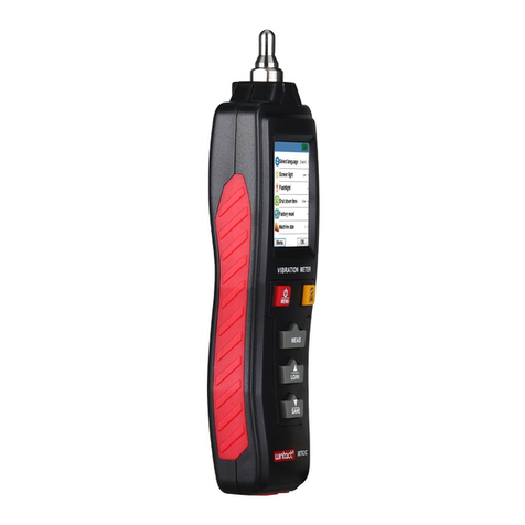
PRUFTECHNIK VIBSCANNER 2 User manual

VIBSCANNER®2
Operating Instructions
Version: 1.0
Edition: 11/29/2017
Doc. no.: LIT 52.200.EN
Translation of the German manual

© 2017 PRÜFTECHNIK Condition Monitoring. All rights reserved.
LEGAL INFORMATION
Copyright notice
These instructions and the product described herein are protected by copyright. The authors reserve all
rights. These instructions must not be copied, reproduced, translated or made available to third parties in
any other form - in part or in full - without prior approval.
Exclusion of liability
Any claims against the authors in relation to the product described in these instructions are excluded. The
authors do not provide any guarantee for the accuracy of the contents of these instructions. Furthermore,
the authors are not in any way liable for any direct or indirect loss arising from using the product or from
using these instructions even if the authors have identified the potential for such a loss. The authors do
not accept any liability for potential faults in the product. This exclusion of liability also applies to dealers
and distributors. Subject to errors and design changes, in particularly in terms of further technical de-
velopments.
Trademark
The trademarks and registered trademarks referenced in these instructions are generally marked as such
and are the property of their owners. The absence of a marking does not however mean that names are
not protected.
VIBSCANNER is a registered trademark of PRÜFTECHNIK AG.
PRÜFTECHNIK Condition Monitoring
Freisingerstr. 34
85737 Ismaning, Germany
Tel. + 49 89 99616-0

Contents
1 - Introduction 7
1.1 Prior to starting 8
1.1.1 Notes regarding these instructions 8
1.2 Safety 10
1.2.1 General safety 10
1.2.2 Intended use 13
1.2.3 Conformity 13
1.3 Legal Notes 14
2 - Description 15
2.1 Interfaces and operating elements 16
2.2 Display 17
2.2.1 Color scheme 17
2.2.2 Sleep mode 17
2.3 Operating keys 18
2.3.1 ON/OFF key 18
2.3.2 ENTER key 19
2.4 Connections 20
2.4.1 Analog IN 20
2.4.2 Charge socket 22
2.4.3 Data interface (Micro USB) 22
2.5 Rechargeable battery 23
2.5.1 Battery status 23
2.5.2 Charging the rechargeable battery 24
2.6 Onboard sensor system 25
2.6.1 Stroboscope 25
2.6.2 RFID reader module 25
2.6.3 Sensor for ambient light 26
2.7 Carrying pouch and shoulder strap 27
2.7.1 Adjusting strap length and hand straps 27
2.8 Transport case 28
2.8.1 Case lock 29
3 - Operation 31
3.1 Operation 32
3.1.1 Touch functions 32
VIBSCANNER 2│Operating Instructions 3

3.2 Display and operating elements 33
3.2.1 Context line 33
3.2.2 Status bar 34
3.2.3 Display field 35
3.3 Device settings 40
3.3.1 WiFi 40
3.3.2 Date & time 41
3.3.3 Units 42
3.3.4 Sensor 43
3.3.5 Display 45
3.3.6 Route settings 45
3.3.7 Language & keyboard 47
3.3.8 Power options 47
3.3.9 About VIBSCANNER 2 48
3.4 Text editor 49
3.4.1 Basic functions 49
3.4.2 Extended functions 49
3.5 Update 51
4 - Route 53
4.1 Preparation 54
4.2 Loading the route onto the measuring device 55
4.2.1 Transferring the route via OMNITREND Center 55
4.2.2 Transferring route via file system 56
4.3 Measuring the route 58
4.3.1 Starting the route 58
4.3.2 Performing the measurement 59
4.4 Measurement tasks 62
4.4.1 Vibration measurement with rotational speed determination 62
4.4.2 Measurement on a production line 63
4.4.3 Manual input 64
4.4.4 Measurement with triaxial sensor 64
4.4.5 Temperature 65
4.5 Coded measurement locations 66
4.5.1 VIBCODE sensor for vibration measurement 66
4.5.2 VIBCODE sensor for measurement location detection 67
4.5.3 Non-contact detection or measurement locations (RFID) 67
4.5.4 Teaching in RFID transponder 68
Edition : 11.2017 4

4.6 RPM measurement using the stroboscope 70
4.6.1 Verifying/measuring rotational speed 70
4.7 Route options 73
4.7.1 Remeasuring 73
4.7.2 Moving measurement into history 73
4.7.3 Deleting a measurement 74
4.7.4 Deleting route from the measuring device 75
4.7.5 Skipping a measurement 75
4.7.6 Documenting the event 76
4.8 Route status 78
4.8.1 Measurement status 78
4.9 Transferring measurement data for analysis 79
4.9.1 Transferring measurement data via direct connection 79
4.9.2 Transferring measurement data via the file system 80
5 - Appendix 81
5.1 Technical data 82
5.2 Upkeep and maintenance 85
5.2.1 Storage 85
5.2.2 Cleaning 85
5.2.3 Warranty 85
5.2.4 Spare parts, accessories 85
5.2.5 Checking the measuring accuracy 85
5.2.6 Disposal 86
5.3 Machine speed finder 87
5.3.1 Function 87
5.3.2 Level of confidence 87
5.3.3 Limits 87
5.4 Kinematic Model 89
5.4.1 Reference speed 89
INDEX 91
VIBSCANNER 2│Operating Instructions 5

Empty page

1.1 Prior to starting
On delivery, check the goods for damaged or missing parts. Note any possibly ob-
jectionable parts on the shipping documents and claim them with the forwarder or your
local PRÜFTECHNIK sales partner.
Service addresses
Feel free to contact us in case of questions:
oHotline: +49 89 99616-0
oFax: +49 89 99616-300
1.1.1 Notes regarding these instructions
These operating instructions describe the measuring device VIBSCANNER 2 and its ac-
cessories. They contain important information regarding safe operation as well as in-
formation for proper and efficient use. They must therefore be read prior to startup and
all other steps.
These instructions were created with due diligence. PRÜFTECHNIK does not guarantee the
completeness, correctness and currency of the data presented here and is not liable for er-
rors or omissions.
These instructions are a part of the product. As such, they must be kept throughout the
product service life. These instructions must be handed over to any subsequent owner or
user of the product.
These instructions were created based on German Standard DIN EN 82079-1.
Text markings
Texts are marked according to their function as follows in these instructions:
Action steps are indented and marked with a filled circle • as bullet point.
oList entries are indented and marked with an empty circle ° as bullet point.
Individual menu items and text elements on the screen are in bold font end enclosed in
square brackets, such as [Delete] or [Units].
The individual menu items in menu sequences are separated by a greater-than sign: [Set-
tings > Units > Acceleration].
8 Edition: 11.2017
1 - Introduction

Warnings are marked with text frame highlighted in yellow:
WARNING!
If there is risk of severe to fatal injuries, the warning is started with a red warning
triangle and signal word WARNING!
CAUTION!
If there is risk of minor to medium injuries, the warning is started with a yellow
warning triangle and signal word CAUTION!
ATTENTION!
If there is risk of property damage, the warning is started with an information
icon and signal word ATTENTION!
Note
General information and tips are marked with a text frame highlighted in gray and
signal word Note
Abbreviations
The following designations are considered equivalent in these instructions:
oVIBSCANNER 2 = measuring device, device
oSensors, cables, brackets = measuring equipment
oDevice technology = measuring equipment and measuring device
VIBSCANNER 2 9
1 - Introduction

1.2 Safety
VIBSCANNER 2 is designed and built following a careful selection of the harmonized norms
to be complied with as well as other technical specifications. The measuring device there-
fore corresponds to state of the art, and ensures the highest degree of safety.
Nevertheless, there are still risks relating to its operation which are to be avoided. Ob-
serve the general safety instructions in this section as well as the warnings embedded in
the overall instructions. Safety instructions explain how you should act in order to protect
yourself, others and objects from harm. The user of the measuring device shall be re-
sponsible for damage and injuries caused by nonobservance of these instructions.
1.2.1 General safety
In addition to the information in these operating instructions, observe the general, legal
and other binding regulations for accident prevention and environmental protection.
These may be, for example:
oHandling hazardous substances
oWearing the required and prescribed personal protective clothing and protective
equipment
oObserve and follow all national and regional occupational health and safety reg-
ulations
oObserve and follow all internal occupational, operational and safety provisions
Residual hazards and protective measures
VIBSCANNER 2 is safe if used as intended. The following damage may occur if used im-
properly:
oPersonal damage
oDamage to the device technology or the monitored machine
Risk of damage to the device
Incorrect use of the measuring device and its accessories may lead to damage and, in the
worst case, to the destruction of the device technology.
oUse original spare parts and original accessories only.
oDuring operation, charging and storage, protect the measuring device from un-
usual external heat (intense sunlight, storage in heated car, direct vicinity to open
flame or heating devices). The temperature ranges specified in the technical data
must be observed.
oThe measuring device meets protection class 65 and is not waterproof. Do not sub-
merge the measuring device in liquids.
10 Edition: 11.2017
1 - Introduction

oIn a loaded industrial environment, the measuring device may have its function im-
paired due to contamination or moisture. Make sure that the protective caps are
attached properly to the measuring device.
oDamaged device technology may reduce the quality of measurement results and in
the worst case falsify the quality. Handle the device technology carefully and pro-
tect it from strong vibrations. Use the transport case to transport and store the
device technology.
oRepairs on the measuring device and the measuring equipment may be performed
by authorized specialist personnel only.
oThe device technology is maintenance-free. Opening the measuring device or the
sensor system by the user is prohibited.
oModifications and changes to the device technology are prohibited.
oImproper operation may damage the touch display. Do not use any scratching or
sharp objects for operation. In addition to using your finger to operate the device,
it is also appropriate to use standard touch pens or touchscreen gloves. Do not ap-
ply too much pressure to the touch display. Light tapping is usually sufficient.
Observe the following safety instructions when handling the rechargeable battery and
the power adapter:
oOnly charge the battery by using the power adapter supplied. Observe the ac-
companying operating manual.
oDo not discharge the battery too deeply (< 15%).
oDischarge the battery so that the remaining battery power is less than 60% if the
device is to be sent by air freight.
oDo not send the device by airfreight if the battery is defective.
Risk of injuries
Improper use of the measuring device or defective equipment may pose a hazard to the
user.
oYou may only operate the device technology with proper training in its operation.
oOnly use the measuring device outside potentially explosive areas.
oImmediately shut down the measuring device and the sensors if malfunctions in-
dicate that they are no longer working properly or if they exhibit visible damage.
oFaults, such as defective plugs or loose connections, must be corrected im-
mediately. Damaged components must be replaced immediately.
VIBSCANNER 2 11
1 - Introduction

Observe the following safety instructions when handling the stroboscope:
oThe stroboscope generates very bright flashes of light. Do not look into the light
source.
oDo not direct the light beam towards people.
oDo not concentrate or focus the light beam.
oThe effects of light can trigger photosensitive epilepsy. Users with a neurological
proclivity for epileptic seizures must not operate the stroboscope.
oInterference with active implants (e.g. pacemakers) cannot be ruled out. Wearers
of active implants must not operated the stroboscope.
oRotating components on the machine appear static in the flashing light of the
stroboscope. Do not reach into the illuminated components
Dangers in industrial facilities!
Risk of fatal or severe injuries!
During measurements on the running machine, the device technology may be damaged
on contact with moving machine parts (e.g., rotating shaft). Cables can wind up and
drawn in. Danger due to fragments.
oInstall the measuring equipment such that no contact with moving machine com-
ponents may occur during the measurement. Contact the competent safety of-
ficer.
oUse the safety release cable between measuring device and sensor cable. This en-
sures that the sensor line is disconnected at the intended point in the case it is
drawn on by rotating machine parts.
oIf possible, always use the measuring device together with the carrying pouch and
the carrying strap.
oThe carrying strap is meant to secure the device from falling down inadvertently
and is designed to be correspondingly sturdy. It can get stuck on protruding sys-
tem components and cause severe injuries. Wear the measuring device so that the
carrying strap cannot get caught and always pay attention to possible sources of
danger, such as open waves or drive belts.
Risk of falling!
oDo not walk through the system while reading the screen or while operating the
device.
Risk of injuries or measuring device damage!
You can injure yourself or damage the sensor system when capturing signals in areas that
are not visible or that are poorly visible.
oWork so that your hands and the sensors are always in your visible range. If ne-
cessary, use a flashlight to illuminate the measurement locations.
12 Edition: 11.2017
1 - Introduction

Risk of incorrect measurements due to electromagnetic interference
High frequency radiation or electrostatic discharge in the vicinity of the measuring device
and measuring equipment can lead to faulty measurements.
oSelect a measurement site with low electromagnetic radiation exposure.
Data security
Risk of data loss!
oBack up the measurement data in the OMNITREND Center PC software after com-
pletion of data acquisition.
oBack up the data prior to resetting the measuring device to the factory settings.
1.2.2 Intended use
The measuring device may only be used for the measurement of electrical signals in the in-
dustrial area taking into account the technical specification. Sensors and cables may only
be used in the specified area. The currently applicable technical specification can be found
in the Condition Monitoring catalog, which can be downloaded free of charge from the
PRÜFTECHNIK homepage.
Any use beyond that is considered unintended and is not permissible. Faulty or im-
permissible use as well as nonobservance of the information in these instructions shall
void the manufacturer’s liability.
If the measuring device is used in a manner not intended by the manufacturer, device pro-
tection may be impacted.
1.2.3 Conformity
VIBSCANNER 2 complies with the relevant European directives. The complete Declaration
of Conformity can be found at www.pruftechnik.com.
VIBSCANNER 2 13
1 - Introduction

1.3 Legal Notes
User Information acc. to Sect.15.21:
Changes or modifications not expressly approved by the party responsible for compliance
could void the user’s authority to operate the equipment.
Compliance Statement acc. to Sect. 15.19:
This device complies with Part 15 of the FCC Rules and RSS Standards: Operation is sub-
ject to the following two conditions: (1) this device may not cause harmful interference,
and (2) this device must accept any interference received, including interference that may
cause undesired operation.
Le présent appareil est conforme aux CNR d'Industrie Canada applicables aux appareils ra-
dio exempts de licence. L'exploitation est autorisée aux deux conditions suivantes : (1)
l'appareil ne doit pas produire de brouillage, et (2) l'utilisateur de l'appareil doit accepter
tout brouillage radioélectrique subi, même si le brouillage est susceptible d'en com-
promettre le fonctionnement.
Class B Statement Sect. 15.105 –)
NOTE: This equipment has been tested and found to comply with the limits for a Class B di-
gital device, pursuant to part 15 of the FCC Rules. These limits are designed to provide
reasonable protection against harmful interference in a residential installation. This equip-
ment generates, uses and can radiate radio frequency energy and, if not installed and
used in accordance with the instructions, may cause harmful interference to radio com-
munications. However, there is no guarantee that interference will not occur in a par-
ticular installation. If this equipment does cause harmful interference to radio or tele-
vision reception, which can be determined by turning the equipment off and on, the user
is encouraged to try to correct the interference by one or more of the following measures:
Reorient or relocate the receiving antenna.
Increase the separation between the equipment and receiver.
Connect the equipment into an outlet on a circuit different from that to which the
receiver is connected.
Consult the dealer or an experienced radio/ TV technician for help.
14 Edition: 11.2017
1 - Introduction

2 - Description
This section provides information about the following topics:
2.1 Interfaces and operating elements 16
2.2 Display 17
2.2.1 Color scheme 17
2.2.2 Sleep mode 17
2.3 Operating keys 18
2.3.1 ON/OFF key 18
2.3.2 ENTER key 19
2.4 Connections 20
2.4.1 Analog IN 20
2.4.2 Charge socket 22
2.4.3 Data interface (Micro USB) 22
2.5 Rechargeable battery 23
2.5.1 Battery status 23
2.5.2 Charging the rechargeable battery 24
2.6 Onboard sensor system 25
2.6.1 Stroboscope 25
2.6.2 RFID reader module 25
2.6.3 Sensor for ambient light 26
2.7 Carrying pouch and shoulder strap 27
2.7.1 Adjusting strap length and hand straps 27
2.8 Transport case 28
2.8.1 Case lock 29
VIBSCANNER 2│Operating Instructions 15

2.1 Interfaces and operating elements
The figures show the interfaces and operating elements on the measuring device.
# Name Function
1Touch display Graphical display and touch-sensitive user in-
terface
2Battery status display (LED) Multi-color LED indicates the battery status
when the display is switched off.
3Sensor for ambient light Automatic adjustment of the display bright-
ness to the ambient light.
4ENTER key Operating key to start the measurement
5Charge socket Connection for power adapter.
6Analog In Connection for sensor.
7ON/OFF button Operating key to switch the measuring
device ON and OFF; activating /deactivating
sleep mode.
8RFID reader module Non-contact readout of RFID transponders.
9Micro USB Interface for data communication
10 Stroboscope Flashlight source to verify the determined ro-
tational speed.
16 Edition: 11.2017
2 - Description

2.2 Display
The display is the main display and operating element on the measuring device. It is
touch-sensitive and is operated using touch functions ("Operation" on page 32).
Note
On delivery, the display is protected with a transparent film. Remove this film
prior to first startup.
2.2.1 Color scheme
VIBSCANNER 2 offers two color schemes used to present the contents on the display. The
“black &white” scheme is suitable for a dark environment. The “default” scheme with its
bright background is ideal for a bright environment.
The color scheme is set in the device settings: [Settings > Display > Color scheme].
Black & white Default
2.2.2 Sleep mode
In sleep mode, the display switches off and the processor consumes less energy. The LED
below the display lights up indicating the battery status and signals the user that the
device is ready for operation.
The device automatically enters sleep mode if it is not operated within a certain period of
time. The period is set in the device settings: [Settings > Power options > Sleep].
To force the device into sleep mode manually, briefly press the ON/OFF key until the dis-
play switches off.
In order to exit sleep mode, press the ON/OFF or the ENTER key.
VIBSCANNER 2 17
2 - Description

2.3 Operating keys
VIBSCANNER 2 has two yellow operating keys: the ON/OFF key on the front side and the
ENTER key below the display.
2.3.1 ON/OFF key
Switching on: Press the ON/OFF key until the battery status LED lights up.
Switching off: Press the ON/OFF key then tap in the context line.
ATTENTION!
VIBSCANNER 2 cannot be switched on anymore at temperatures above 70 °C
(158 °F). Observe the permissible temperature range for operation ("Technical
data" on page 82).
Automatic switch-off
VIBSCANNER 2 switches off automatically if not operated within a certain period of time.
The period is set in the device settings: [Settings > Power options > Power off].
Activating sleep mode manually
Press the ON/OFF key, until the display switches off ("Sleep mode" on page 17).
Forced switch-off
If VIBSCANNER 2 locks up / freezes, press the ON/OFF key, until the display switches off
(approx. 5 seconds). Switch on the device again.
18 Edition: 11.2017
2 - Description

2.3.2 ENTER key
The ENTER key is used to start a measurement or to confirm a selection. Three pressure
points simplify left- or right-handed operation using the thumb.
The ENTER key features three pressure points The OK element in the context line can also be
confirmed with the ENTER key.
VIBSCANNER 2 19
2 - Description

2.4 Connections
VIBSCANNER 2 features an analog measuring channel, a charge connection, and an in-
terface for data exchange via USB. All connections are protected against humidity and con-
tamination using flexible cover caps.
Charge socket (left) and multipole analog measuring channel (analog IN, right) at the bottom of the
device.
Micro USB connection for data exchange.
2.4.1 Analog IN
The analog measuring channel is used to connect vibration sensors. A specifically tagged
multipole sensor cable is available for every sensor type (e.g., CLD, IEPE, triaxial, etc.).
WARNING!
Severe injuries due to drawing in of the sensor cable possible during meas-
urements on a running machine. A predetermined breaking point in the cable
length triggers when the cable connection to the measuring device is drawn in.
Always use the provided safety release cable between measuring device and
sensor cable.
20 Edition: 11.2017
2 - Description
Table of contents
Other PRUFTECHNIK Measuring Instrument manuals


