PS Audio Power Plant P500 User manual

Table of Contents
1....What’s in the Box
2....Warning
2....Safety Instructions
2....Overview
3....Installing the Upgrade
6....Testing the Power Plant
6....MultiWave II+ Operation
7....MultiWave II+ Waveforms
8....Warranty and Service Issues
8....Contact Information
What’s in the Box
• One microchip
• One chip puller
• One plastic dentist mirror
• One anti-static wrist strap
• One instruction booklet
MultiWave II+Installation
Instructions
P500

Warning
To prevent fire or shock hazard, do not
expose the MultiWave II+ kit to rain or
moisture. To avoid electrical shock, the
Power Plant must be unplugged and fully
discharged before opening.
To prevent electric shock, use a 3 prong,
grounded type power cable.
Any change or modifications not expressly
approved in the manual could void your
warranty.
Safety Instructions
General Instruction:
Read the operating instructions provided
with your MultiWave II+ kit.
Retain the operating instructions for later
use and reference
Completely discharge the Power Plant
before opening the chassis by unplugging
the unit for at least 12 hours.
Unplug the Power Plant from the wall outlet
before changing the fuse or performing any
upgrade or service.
Do not operate the Power Plant near water.
Avoid placement near a water reservoir or
excessive moisture.
When replacement parts are required, be
sure they are specified by the manufacturer
to have the same characteristics as the orig-
inal. Unauthorized substitutions may result
in fire, electric shock, or other hazards.
Do not operate with faulty or frayed power
cables.
MultiWave II+™ operation:
Any turntable or equipment with AC
synchronous motors, such as some cooling
fans should not be used with MultiWave II+
unless it is in the sine wave mode. This
equipment must be used with sin mode.
We recommend the use of the Sine Wave
[sin], or TubeWave™ [tub] with any type of
tube based audio products.
Overview
Read the entire instruction manual
before starting the installation.
The benefits the Plus upgrade kit will pro-
vide for your MultiWave II equiped power
plant are:
• Fine tuning for turntables
• Clean Sweep
The MultiWave II+ upgrade is a fairly simple
process. If you have any questions at any
time, please contact your dealer, distributor
or PS Audio by e-mail, fax or telephone at
the numbers listed at the end of the instruc-
tions.
All P500 Power Plants were shipped from
the factory with MultiWave II installed.
Here’s the quick procedure.
1. Remove the input power cable from the
rear of the power plant, wait a few hours.
2. Remove the top cover using a Phillips
screwdriver.
3. Remove the power connector that con-
nects the front panel board with the big
power transformer.
4. Remove the bolt holding the power trans-
former in place, pull the power trans-
former aside and gain access to the front
panel board.
5. Replace the microchip on the front panel
board.
6. Re-install the power transformer.
7. Reconncet the power cable to the front
panel.
8. Replace the top cover.
9. You are done.
2
Installing the Upgrade
Before beginning the Plus upgrade, you will
need to do the following:
The Night Before
Unplug the Power Plant the night before (or
at least several hours before) you plan to do
the upgrade. Really unplug it! Take out the
input power cable and take out all the power
cables connecting to your a/v equipment. By
letting the Power Plant sit overnight, most of
the energy stored in the power supply will
drain away.
The Day of the Upgrade
Assemble the following tools in your work
area:
• A clean table to place the Power Plant
while you are working.
• A #2 Phillips head screwdriver.
• A 1/2 inch nut driver or open end wrench
and a 1/2 inch deep-socket wrench
• A desk lamp, gooseneck lamp or other light
placed next to the Power Plant so you can
see what you are doing.
• The MultiWave II+ Upgrade Kit.
Before opening the Power Plant
• Ensure it is fully unplugged and dis-
charged for at least several hours or
more.
Disassembly
Keep the P500 upright so you have easy
access to
the top. Use
#2 Phillips
screwdriver
to remove the
screws affixing
the top cover
of the P500.
Remove the
top cover and
set it aside.
Locate and
disconnect the
power cable
Note the big,
round toroidal
power trans-
former. Locate the power connector from
the transformer to the front panel board as
shown in the picture. Squeeze the connec-
tor’s side tabs and gently pull the connector
out. Do NOT remove the 2nd connector that
attaches the transformer to the rear power
inlet board. Remove ONLY the front panel
power connector.
Remove the power transformer
Using the 1/2” open end wrench or nut driver
on the bottom of the P500, hold the trans-
former’s hold down bolt head, while you
remove the inside nut holding the transform-
er in place using the 1/2” socket wrench.
Move the transformer away from the front
panel so you gain access to the front panel
board. Be careful not to stress the wires
connecting the transformer with the rear
power inlet board.
Removing the old front
panel microchip
Locate the chip puller
enclosed with the MultiWave
II+ package. The chip puller
will be used to carefully
remove the old microchip.
Notice the chip puller has
two small prongs. Put the
two prongs of the chip puller
between the chip and the
socket on the left and right
side. There is a small gap
between the chip and the
socket for you to insert the
prongs of the chip puller.
It may take a little wiggling
of the chip puller to get its
prongs under the chip.
Squeeze the chip puller together and pull
3

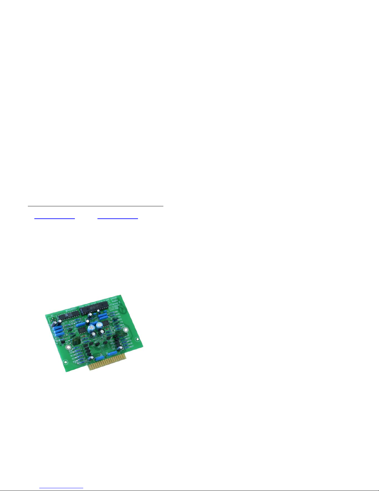
the microchip straight out of its socket. It
may take a tug. Pull straight back. When the
old microchip pops out of its socket, lay it
out of the way.
Great work. You are almost done. Take
a break.
Take this time to attach the anti-static wrist
strap to your wrist by wrapping the clear
sticky end around your wrist like a bracelet.
Remove the adhesive strip from the copper
tail and attach it to an exposed aluminium
surface inside the Power Plant chassis.
Installing the new front panel microchip
Carefully open the sealed end of the silver
anti-static bag (you are wearing your wrist
strap now, aren’t you?). Carefully remove
the new processor chip from the silver bag.
The chip is pressed to a small piece of black
foam. This special foam protects the chip
from static. Do not remove the chip from
the antistatic foam at this time.
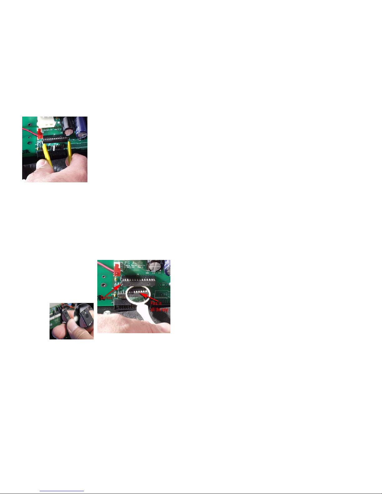
Notice that the chip has a “half moon” on
one side. There
is also a white
dot to help iden-
tify the direction.
Looking from the
rear of the unit,
this dot must face
to the LEFT.
Now, carefully use your fingers to pull the
chip straight out of the black protective
foam. Yep, you can use the chip puller for
this if you like. The key is pulling the chip
straight out of the foam so that we do not
bend any of the little legs.
After you pull the chip out of the foam, lay
it so it rests on its legs on top of the black
foam. It will look a lot like a bug - a healthy
bug with straight legs. If any of the legs are
not straight, use a finger nail to straighten
it.
Do not rush the next step. Please read
this next section again before you go on.
Do you have a light shining inside the Power
Plant? Is it well lit? Do you have your read-
ing glasses on? Just checking.
You are going to next insert the chip into the
socket. Do this by grasping the small sides
of the chip with your thumb and forefinger.
Now, carefully line up the legs of the chip
with the holes in the socket. BE VERY
CAREFUL. Only lightly press the chip into
the socket at this time - just enough for the
socket to hold the chip. You just want to get
the legs started. Do not press hard on the
chip at this time.
Now make sure each leg of the microchip
is inserted in the corresponding socket
hole. That’s what the little dentist’s mirror
is for. You should be able to see the pins
on the top of the socket with your eye. The
dentist mirror will help with the lower set of
pins. Most problems of MultiWave installa-
tion have been found to be people’s failure
to get the bottom row of legs in the socket
properly. Make double sure. It’s easy for
the pins to be in the socket but not be seated
electrically. Make sure the bottom pins look
seated in an identical fashion to the top row
of pins.
4
When you are sure that each leg of the
microchip is straight and lined up correctly,
top and bottom rows, press the microchip
down into the socket. The chip will seat
almost flush into the socket.
Now, use the mirror again to inspect the
microchip and socket. The microchip must
be flush in the socket and no pins should be
bent or coming out of the socket.
Inspect your work
You are almost done!
Carefully inspect you work one more time
before you button up. The items you want to
check will be:
• The new microchip on the front panel
display board is inserted correctly. Use that
mirror if you need to!
Replace the transformer
Reverse the procedure you went through to
remove the transformer. As long as it is sit-
ting on its foam pad, insert the bolt through
the hole, thread the nut back on and tighten.
Make the sure the transformer is firmly
mounted in place and that its orientation is
such that the power connector will easily
reconnect to the front panel board.
Reconnect the power cable from the trans-
former to the front panel board. Make sure
that all the wires in the unit look ok.
Make sure the transformer is tight.
Replace the top cover
Make sure the holes in the top cover line
up with the PEM threaded hardware in the
chassis and then place the screws back in
and tighten the cover in place.
Testing the Power Plant
To make sure everything is tip-top, perform
the following tests:
• Plug the Power Plant into a power source.
Do not plug anything into the back of the
unit at this time.
• Next, press the front panel power button.
The Power Plant front panel should indi-
cate [Sin] If it does, the Power Plant is fully
operational and you are now a certified
PS Audio MultiWave II+ upgrade installer.
We are proud of you, but you may want to
keep your day job.
• Don’t forget to remove the anti-static wrist
strap before leaving you work area.
YOU’RE DONE! Really. But keep that den-
tist mirror close by. Who knows what micro-
chips or teeth might need inspecting.
NOW, hold on to your favorite listening chair
and experience MultiWave II+. We are quite
sure you will be as amazed as we were the
first time we listened. Use Clean Sweep
and do a full system clean after every-
thing’s turned on and ready to go.
Its benefitrs become addicting after a while
so Clean Sweep the system before every
serious listening session.
If you have any questions about the instal-
lation process, stop and contact us. We are
here to help.
MultiWave II+ Operation
Notice of MultiWave II+ operation:
Any turntable or equipment with AC
synchronous motors, such as some cooling
fans should not be used with MultiWave
patterns. This type of equipment must be
used with 60Hz sin mode.
We recommend the use of the sine wave
[sin], or TubeWave™ [tub] with any type of
tube based audio products.
There are five available display modes on
the front panel of the Power Plant. The
Mode button will cycle through the following
five modes:
1. Waveform setting
2. Frequency generated (sin mode only)
3. Voltage produced
4. Wattage produced
5. Display blanking mode
6. Clean Sweep
Waveform setting
This mode will display the name of the
5

waveform presently being generated.
For more information about each of the
MultiWave settings, see your original
MultiWave II+ Waveforms section of the
owner's manual.
Frequency generated
The frequency setting will only be displayed
if the Waveform menu is set to Sin.
This mode will display the frequency the
Power Plant is generating. The frequency
can be adjusted in 1 hertz increments from
50Hz to 120Hz by using the Up and Down
buttons. The default setting is 60Hz.
New with MultiWave II+ is the ability to fine
tune the frequency which is particularly
useful with turntables.
Frequency Fine Tuning Turntables
1) After selecting the desired frequency,
press the Mode Up Button. This will take
you to the frequency fine tuning menu.
2) You can go up or down in 0.0625Hz steps
up to a full +/- 1hz of range. The display
will read -16 to 0 to 16. Each step is
0.0625Hz.
3) If you change the main frequency, the fine
tuning value will be cleared.
Clean Sweep
Clean Sweep is a revolutionary new feature
of the Power Plant that, in effect, cleans
and demagnetizes the power supplies and
power cables of all connected equipment.
We recommend running this feature before
every serious listening session. There is a
60 second Clean Sweep mode, which is to
be used for initial cleaning before listening.
There is a Quick Sweep mode that will clean
for 5 seconds and is designed for use as a
touch up cleaning action when needed.
1) Press the Mode Up Or Mode Down
Button until the word CLEAN appears on
the display.
2) For a full system cleaning process (60
seconds), press the edit down button.
3) For a quick clean (5 seconds), press the
edit up button.
4) The cleaning process is complete once
the countdown stops and the world
CLEAN is displayed on the display.
Warranty inside the U.S. and
Canada
PS Audio’s warranty is 3 years parts and
labor, from the date of original purchase.
This means that we warranty the product
itself regardless of ownership, new or used.
Warranty outside the U.S. and
Canada
PS Audio has authorized distribution in many
countries of the world. In each country, the
authorized importing retailer or distributor
has accepted the responsibility for warranty
of products sold by that retailer or distributor.
Warranty service should normally be obtained
from the importing retailer or distributor from
whom you purchased the product. In the
unlikely event of service required beyond the
capability of the importer, PS Audio will fulfill
the conditions of the warranty. Such product
must be returned at the owner’s expense to
the PS Audio factory. Contact your PS Audio
distributor or the PS Audio customer service
department for more information.
Service issues
Should your unit ever require service or if
you have any technical questions about the
MultiWave II++ kit, you must either contact
your dealer (PS Audio if purchased direct) or
your PS Audio distributor. No equipment will
be received at our service facilities without
an attached RA number.
If purchased through an authorized PS
Audio dealer or distributor, the RA number
must be obtained by the dealer or distributor.
If the product was purchased from PS
Audio direct, this can easily be obtained by
contacting PS Audio at:
Phone - 720.406.8946
Fax - 720.406.8967
http://www.psaudio.com
6
7
Other manuals for Power Plant P500
1
This manual suits for next models
1
Other PS Audio Computer Hardware manuals