PSA PAN780KID User manual

for intercomsChoose
PAN780KID
psaproducts.com.au
1300 772 776
enquiry@psaproducts.com.au
for intercomsChoose
psaproducts.com.au
fire •security •intercomsfire •security •intercoms
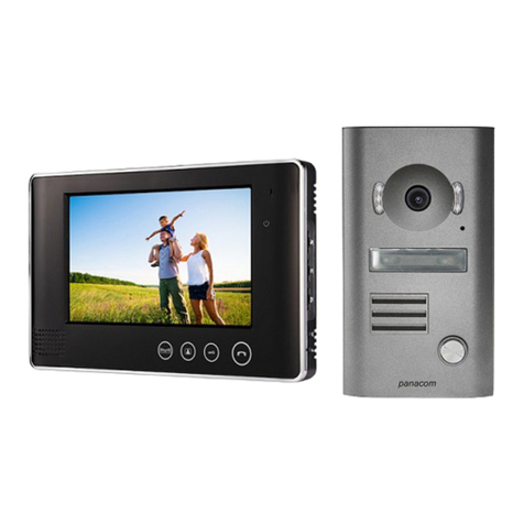
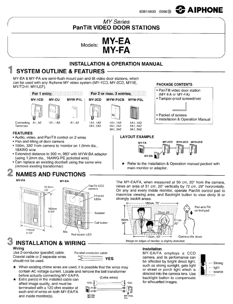
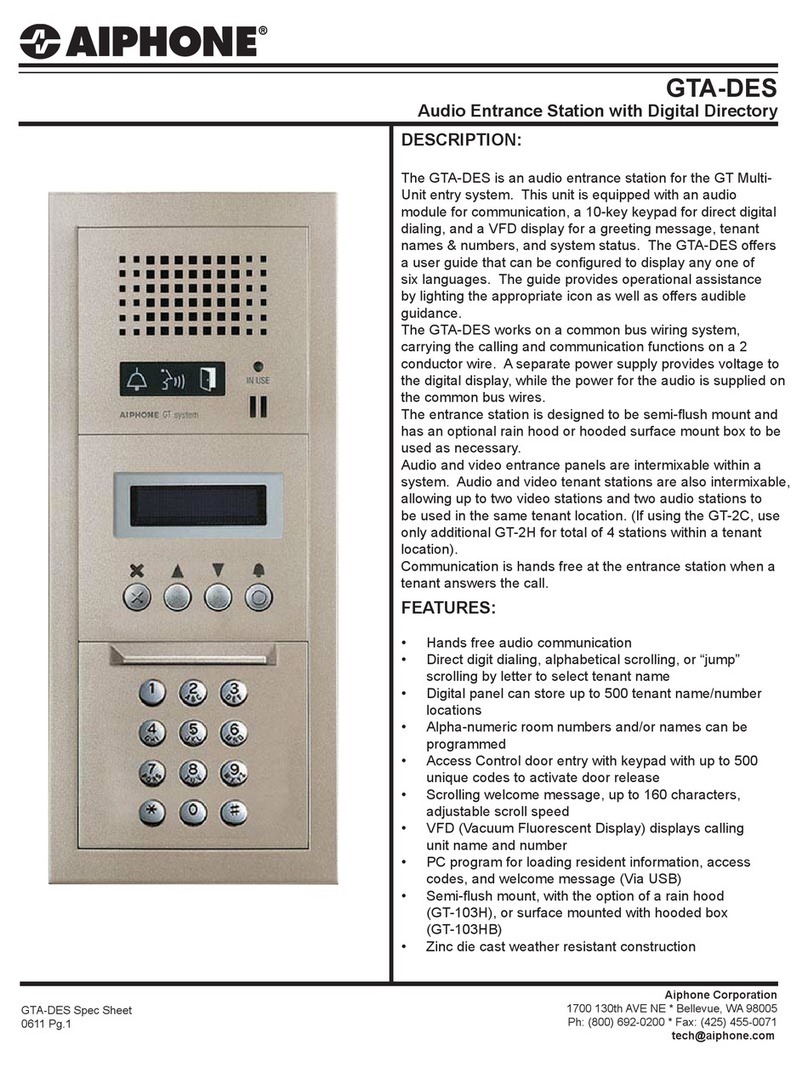
COLOUR VIDEO DOORPHONE KIT
INstructIoN mANuAl

1 2 2
1. FEATURES
1. 21mm slim indoor monitor with touch buttons.
2. Weather resistant outdoor camera
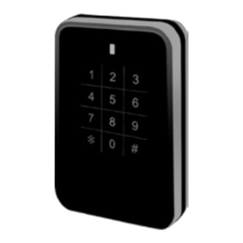
3. Built in RFID reader within door camera for keyless entry.
4. 7” LED screen, no radiation low power consumption and high definition.
5. Hands free communication.
6. Surface touch function.
7. Unlock two doors respectively.
8. Monitoring the outside of house.
9. Fourteen polyphonic melodies.
9. Ring volume, talking volume, chroma and brightness adjustable.
3. OUTDOOR CAMERA SPECIFICATIONS
Camera
Speaker
Infrared Light
Microphone
Call Connection
Terminals
Name Plate
ID Card
Touching Zone
SET RUN
ID Unlock PCB
CONTENTS
PAGE
1. Features 2
2. Kit Components 2
3. Outdoor Camera Specifications 2
4. Indoor Monitor Specifications 3
4. Indoor Monitor Installation 4
5. Outdoor Camera Installation 4
6. Installation & Maintenance Notes 5
7. ID Card Programming 6
8. Wiring & Maintenance Instructions 7-8
9. Operating Instruction 9
10. Warranty Statement 10
2. KIT COMPONENTS
•One indoor monitor •One outdoor camera
•One adapter •One bracket for indoor monitor
•4 cards
(Adding Card, Delete Card, 2 x User Cards)
•Screws
1. IR distance approx 3m
2. Automatic gain control
3. Working temperature: -20°C~50°C
4. Resolution: CCD more than 420 TV line
5. Outdoor camera dimension:
98 (W) X 142 (H) X 38 (D) mm
6. Door lock voltage: 12VDC 500mA
7. RFID door release time: 3 seconds

3 4 4
5. INDOOR MONITOR INSTALLATION
Bracket
1. Fix the bracket of the video indoor monitor on the wall with screws
(Picture 1).
2. Hang the monitor on the bracket after finishing the wire connection.
Plug the enclosed adapter into the sockets of AC power and the monitor
(Picture 2).
Picture 1. Picture 2.
1. Adapter input voltage: AC220V-240V/50Hz
2. Adapter output voltage, output current: DC15V 1200mA
3. Talking last time: 120S±10%
4. Monitoring last time: 40S±10%
5. Working distance: 30M (5 x 0.5mm2)
6. Power consumption: standby <0.5W, working <10W
7. Illumination intensity: 2 luces
8. Visual angle: 92° wide-angle
9. Working temperature: -10°C~40°C
10. Relative humidity: 10-90%(RH)
11. Indoor monitor dimension: 232 (W) X 140 (H) X 21 (D) mm
Chroma Adjuster
Brightness Adjuster
Talking Volume Adjuster
Ring Volume Adjuster
Ring Selection Adjuster
PARAMETER SPECIFICATIONS UNIT
Screen Size 7.0 Inch
Resolution 480 x 3 x 234 Dot
Active Area 154.1 (H) X 86.58 (V) mm
Pixel Size 0.107 (W) X 0.37 (H) mm
Screen Figure Dimension 169.4 (W) X 100 (H) X 5.7 (D) MM
4. INDOOR MONITOR SPECIFICATIONS
Microphone
Power Indicator Light
Talk
Door Release
Monitor
speaker
Gate Release

5 6 6
6. OUTDOOR CAMERA INSTALLATION
Picture 1. Picture 2.
1.0 Nameplate
1.1 To label the name plate, remove the 4 screws on the back of the door camera & carefully remove the
cover. (picture 1)
1.2 Unclip the plastic nameplate cover, label the nameplate & clip back the plastic cover (picture 2)
1.3 Refit the rear cover & screws.
2.0 Camera
2.1 Install the mounting base of door camera at approximate height of 150-160cm from the ground.
2.2 Never install door cameras directly facing sunlight
2.3 Terminate the cables
2.4 Mount door camera on mounting base and secure with allen screw on the bottom of camera.
wall bracket
door camera

7 8 8
7. WIRING & MAINTENANCE INSTRUCTIONS
Door Station Terminal Legend:
1= Audio Wire
2= Ground Wire
3= Video Wire
4= Power Wire
5= Lock +
6= Lock -
7= ID (used only for door station with proximity reader)
Indoor Monitor Terminal Legend:
1= Audio Wire
2= Ground Wire
3= Video Wire
4= Power Wire
5= Ground Wire (used with 2 Door Controller Only)
6= Monitoring Wire (used with 2 Door Controller Only)
7= ID (used only for door station with proximity reader)
Cable Specifications:
• 0to30m:minimumCAT5or5CoreStranded0.50mm2
• 30to80m:minimum5coreStranded0.75mm2
1. To avoid any interference, all intercom cables should maintain 50mm separation from 240VAC wires
2. Never install door camera directly facing sunlight. This will create a white image on indoor monitor
and may damage the camera lens over time.
3. Do not install the monitor or power supply in areas of high temperature or high humidity.
4. To clean the monitor or door camera, use only a damp soft cloth. Do not use cleaning agents,
chemicals or spray directly with water.
5. Please note, nearby wireless devices may cause fuzzy pictures due to interference from radio waves.

9 10 10
8. ID CARD PROGRAMMING
This kit includes four pre-programmed cards.
1 x Adding Card
1 x Deleting Card and
2 x User Cards
Follow the below steps to add, delete or re-program add/delete cards
Adding User Cards:
Step 1: use the adding card to touch the ID card touching zone of the outdoor station.
Step 2: use the user card to touch the same area.
Step 3: use the adding card to touch the same area. Then the new user card is successfully added. At most
1000 user cards can be added.
Deleting User Cards:
Step 1: use the delete card to touch the ID card touching zone of the outdoor station.
Step 2: use the user card to touch the same area.
Step 3: use the delete card to touch the same area. Then the user card is successfully deleted.
Re-programming Add/Delete Cards:
If the user loses the adding card or delete card, he or she can re-program a new cards by following these steps:
Step 1: open the back cover of outdoor station.
Step 2: please turn off the power, and let the ID unlock PCB jumper wire to be SET condition.
Camera
Speaker
Infrared Light
Microphone
Call Connection
Terminals
Name Plate
ID Card
Touching Zone
SETRUN
ID Unlock PCB
Step 3: turn on the power, and use two ID card to touch the ID card touching zone of the outdoor station
accordingly. If there is a long ring sound after the second ID card touching, the re-setting is successful.
Step 4: turn off the power, and let the jumper wire to be RUN condition. The first ID card will be adding card,
and the second will be delete card.

11 12 12
10. Warranty Statement9. OPERATING INSTRUCTION
1. Rings/chimes will be heard & images of visitors will be seen on the monitor once the
CALL button of door camera is pressed.
2. To talk to the visitor, touch TALK .
3. If the system is connected to an electric strike, touch DOOR UNLOCK
4. If the system is connected to a motorised gate, touch GATE UNLOCK
5. To end the conversation, touch TALK again. Talk mode will automatically shut down
after approximately 120 seconds if not ended.
6. To manually view or monitor the front door, touch MONITOR .
7. To end monitoring, touch MONITOR again. Monitoring mode will automatically end
after approximately 40 seconds.
8. To adjust brightness, colour & talking volume, use the dials on the right side of monitor.
9. To adjust ring tones & volume, use the buttons on the right side of monitor.
1 PSA Products Pty Ltd (ABN: 99 076 468 703) of 17 Millicent Street, Burwood 3125 Victoria, Australia
warrants this product for a period of two years from the date of purchase, as reflected on the Authorised
Reseller’s or Distributor’s invoice / receipt provided to you. PSA Products Pty Ltd will repair or replace the
product (at the option of PSA Products) due to any manufacturing defect, at the cost of PSA Products Pty
Ltd (excluding any labour costs relating to removal or re-installation of product, and transport costs).
2 This warranty shall not apply to the product if it has been damaged, modified, abused or altered after the
date of purchase, or if it fails to operate due to improper maintenance.
3 To the extent permitted by law, the liability of PSA Products Pty Ltd arising from the sale or under the
terms of this limited warranty shall not in any case exceed the cost of replacement and subject to this
clause. In no case shall PSA Products Pty Ltd be liable for consequential loss or damages resulting from the
failure of the product or breach of this, or: Any other warranty, express or implied, loss or damage caused
by failure to abide by the instructions supplied in the leaflets.
4 To the extent permitted by law, PSA Products Pty Ltd., makes no warranty, expressed or implied, written
or oral, including that of merchantability or fitness for any particular purpose, with respect to the
consumer replaceable battery if any. A product with non-serviceable built-in battery is covered under
warranty of the product as per point 1.
5 This warranty is provided in addition to other rights and remedies you have under law: Our goods come
with guarantees that cannot be excluded under the Australian Consumer Law. You are entitled to a
replacement or refund for a major failure and compensation for any other reasonably foreseeable loss or
damage. You are also entitled to have the goods repaired or replaced if the goods fail to be of acceptable
quality and the failure does not amount to a major failure. What constitutes a major failure is set out in
the Australian Consumer Law.
6 To make a claim under warranty, take the product (with a proof of purchase) to the store where you
purchased the product or contact PSA Products Pty Ltd. Phone (03) 9888 9889. or Email: enquiry@
psaproducts.com.au with details, proof of purchase or expense claim in writing.
Table of contents
Other PSA Intercom System manuals


