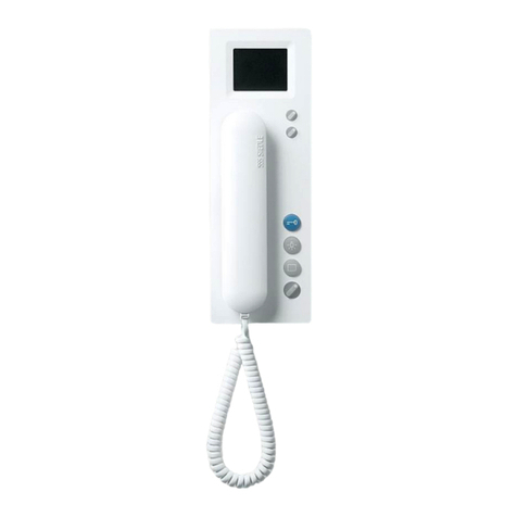
PSA Panacom PANAIP7M User manual

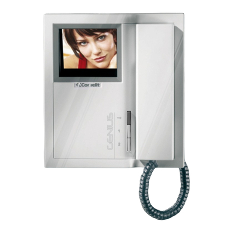
TCP/IP VIDEO DOOR PHONE
QUICK SETUP GUIDE
MODEL NO: PANAIP7M / PANAIP7MW / PANAIP7GM

2 3
1. Technical Specifications 4
2. Packing Contents 5
3. Name and Functions of Each Part 6
3.1 Front and Rear Part 6
4. Connection Diagram 8
4.1 System Layout 8
4.2 Wiring Diagram 9
5. Installation 10
6. Operation Description 12
6.1 Main Page 12
7. Quick setup 14
71 Enter setup page 14
7.2 Set Encoder and Unit ID 14
7.3 Set Unlock Password 15
7.4 Wi-Fi Settings Only for PANAIP7MW monitor 16
8. User Manual 17
Please follow these instructions to prevent any personal danger or property loss.
Warning: To avoid death or serious injury
Do not disassemble, install, or repair this product on your own accord
Do not place the product near a hot or humid place
Do not forcibly bend the cord or put a heavy object on the product
Do not use water, thinner or a detergent for removing oil products when
cleaning the exterior
Do not connect to other products while in use
Make sure to clean with a dry cloth to prevent any breakdown or electric
shock
If the product emits a peculiar noise, odour or smoke, immediately
disconnect the power, and then contact PSA Products.
Do not insert the power plug into a 240VAC mains socket with a wet hand
Caution: To avoid personal injury or property loss
Ensure that dust or foreign substances do not collect on the product
Ensure foreign substances do not enter the product
Avoid direct sunlight or heat upon the device
Install the product on a flat & stable location
Unplug the product from AC Mains power if it would not be used for a long time
Do not unplug the micro SD card while recording, as this may cause loss of data
TABLE OF CONTENTS WARNING AND CAUTION

4 5
• 7” capacitive touch screen monitor. Resolution: 800*480 pixels
• Zone alarms (4-zones max.)
• Supports up to 19 door panels
• Video Encoding: H.264
• Network Connection: Ethernet (POE)
• Operating Voltage: 18V (POE)
• Operating Current: 300 mA (max: 500 mA, stand-by: 180mA)
• Operation Temperature: -10~55ºC
• Operating system: Linux
• Internal Flash Memory (Internal storage: 100 pictures)
• Micro SD-Card Slot (Micro SD-card not included with Monitor)
• Dimensions(mm): Indoor monitor: 210(W) x 140(H) x 20(D)
Guard unit: 326(W) x 206(H) x 56(D)
Indoor monitor (PANAIP7M excludes 4 pin wiring cable)
Main Body Wall bracket 2 pin wiring cable DC connector Quick start guide
KA M4*35mm
Mounting screw
M4*35mm plastic
expansion pipe 8 pin wiring cable 4 pin wiring cable
Guard unit
Main Body Handset DC connector Helical line
KM M3*5mm
Mounting screw Left bracket Right bracket Quick start guide
1. TECHNICAL SPECIFICATIONS 2. PACKING CONTENTS

6 7
3.1 FRONT AND REAR PART
Indoor monitor (Model No: PANAIP7M & PANAIP7MW)
NO. Part Name
1Power Indicator White LED when power on
2Message Indicator White LED flashes when have unread message/call
3Alarm Indicator White LED flashes when have alarm
4Screen 7-inch digital TFT LCD
5 Microphone Receive voice from the user
6 Micro SD Card Slot Socket for micro SD card
7 Connection Port Interface for sensor
8 Connection Port Interface for doorbell
9 DC Power 15~20 VDC (1A) power supply
10 RJ45 Connector Interface for RJ45
11 Video Input Interface for Video door bell (Not supported in PANAIP7M)
12 Speaker
Guard unit (Model No: PANAIP7GM)
NO. Part Name
1Handset
2RJ11 Connector Connection for helical handset cable
3Power Indicator Red LED when power on
4Screen 7-inch digital TFT LCD
5 Speaker Receive voice from the user
6 Door Release Button Press button to release door lock
7 RJ45 Connector Interface for RJ45
8 DC Power 12~20 VDC (1A) power supply
3. NAME AND FUNCTIONS OF EACH PART

8 9
4.1 SYSTEM LAYOUT
Remark:
• The distance between the PoE Switch and other devices (indoor monitor, door panel,
network switch, guard unit) must not exceed 70 meters.
• The system supports up to 98 buildings, and a maximum of 32 IP cameras.
• Each room supports up to 3 monitors.
• The address of the other devices can only be set after first configuring the address
of the 1st Building Panel (to either 5-Digit:01-801, or 6-Digit:01-9001).
4.2 WIRING DIAGRAM
is the interface socket for alarm sensors, and is located at the back of the Monitor. Alarm
sensors for four alarm zones can be connected to these ALM1, ALM2, ALM3, and ALM4
terminals.
4. CONNECTION DIAGRAM

10 11
INDOOR MONITOR
Standard installation height of door panel puts the lens about 1550mm above the oor.
Hence, the centre of the camera should be about 1540mm above ground level.
1650
1540
1550
Monitor Installation Location
Install the Monitor about 1500mm from floor level so that the centre of the screen is at eye
level. This means the centre of the metal wall bracket is 1450mm from floor level.
Installing the Indoor Monitor
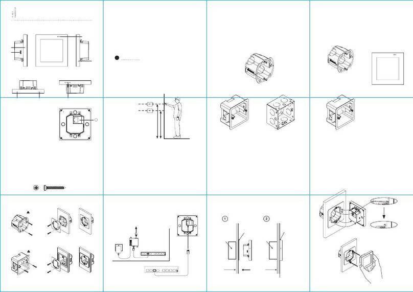
1) Remove mounting bracket from behind monitor and fix it onto the wall with screws.
2) Install the cable and connect the system according to the wiring diagrams in Section 4.
3) Hang the monitor onto the mounting bracket.
GUARD UNIT
Installing the Guard Unit
1) Place the guard unit on a level desktop;
2) Fix the bracket to the rear of the monitor with screws.
3) Install the cable and connect the system according to the wiring diagrams in Section 4.
5. INSTALLATION

12 13
The illustrations in this section are based on Model Nos. PANAIP7MW and PANAIP7GM.
6.1 MAIN SCREEN
Touch the screen anywhere in standby mode, the Main Page will be displayed:
ICON DEFINITION
The following table shows each icon on the Main Page and its function.
Enter the call menu Enter the message menu
Enter the monitor menu Alarm management
Picture storage Enter the setting menu
No network indicator [Do Not Disturb] mode indicator
WIFI connection1Emergency Call (to Guard)
Alarm Mode: Set the monitor for Leaving or Presence mode
(Default Password: 9999)
1Not available for Model Number PANAIP7M.
• The Guard unit does not have the two icons for Emergency Call and Alarm mode.
6. OPERATION DESCRIPTION

14 15
7. QUICK SETUP
Please setup Door Panel before proceeding to the next step.
7.1 ENTER SETUP PAGE
Select “Setting”
7.2 SET ENCODER AND UNIT ID
Select “Engineering Setting”
Enter Engineering Password (Default: 0000)
Select “Device Information”
Select “5 digits Encoding” if door station is
set to 5 digits Encoding.
For 6 digits Encoding refer to
monitor manual.
Enter Building Number: 1
Enter Room/Unit number: ___
Enter Ext. No: ___ (1st monitor always 1)
Select to complete.
Monitor will restart.
7.3 SET UNLOCK PASSWORD
The password must be 4 digits and cannot
be identical digits (e.g. not ‘3333’
nor ‘8888’ or consecutive numbers
(e.g. not ‘1234’ nor ‘4567’).
Enter the Setup page: Select “Setting”
Select Unlock Password
Enter a 4-digit Password
Enter confirm Password.
Touch blue screen to hide keypad
Select to save the information.
Select to exit

16 17
7. QUICK SETUP 8. USER MANUAL
7.4 WI-FI SETTINGS ONLY FOR PANAIP7MW MONITOR
Select Wi-Fi
Select Wi-Fi config
Select your Wi-Fi on screen
and enter Wi-Fi password.
Call forward selection:
Off - Stop all call forwarding
Immediate - Forward call to phone app.
Timeout - Forward call when call has not
been answered by monitor.
Press to return to setting
Press to return to main screen.
To download User Manual, go to: www.psaproducts.com.au

17 Millicent Street, Burwood, VIC 3125 Australia
Tel: 1300 PSA PRODUCTS (1300 772 776)
Fax: (03) 9888 9993
This manual suits for next models
2
Table of contents
Other PSA Intercom System manuals

