PSE LG 05 SS Parts list manual

— 5 GALLON SPOT SPRAYER —
MODEL # LG 05 SS
•5 Gallon Polyethylene Tank
•1.0 GPM Demand Pump
•Lever Handgun
•Rechargeable 12V Battery
•AC Charger w/built in Storage
Compartment
•Telescoping Handle
•Large 8 Inch Wheels
•9 foot coil hose
Assembly / Operation Instructions / Parts
PRECISION SPRAY EQUIPMENT, a divison of Green Leaf, Inc. 9490 N BALDWIN ST FONTANET, IN 47851 www.grnleafinc.com
a division of Green Leaf, Inc
®
PRECISION SPRAY EQUIPMENT
PSE
a division of Green Leaf, Inc
®
PRECISION SPRAY EQUIPMENT
PSE
LG 05 SS

— GENERAL INFORMATION
— WARRANTY / PARTS / SERVICE
— ASSEMBLY
— BATTERY CHARGING
— AFTER SPRAYING
— WINTER STORAGE
After use fill the sprayer part way with water. Star
t
the sprayer and allow clear water to be pumped
through the plumbing system and out through the
spray wand. Refill the tank about half full with
plain water and use a chemical neutralizer such
as Nutra-Sol® or equivalent and repeat cleaning
instructions. Flush the entire sprayer with the
neutralizing agent. Follow the chemical manu-
facturer’s disposal instructions of all wash or
rinsing water.
Drain all water and chemical out of sprayer, pay-
ing special attention to pump and valves. These
items are especially prone to damage from
chemicals and freezing weather. The sprayer
should be winterized before storage by pumping
a solution of RV antifreeze through the entire
plumbing. Proper care and maintenance will pro-
long the life of the sprayer.
— TROUBLE SHOOTING
Pump will not run:
1. Check inline fuse on the wiring harness. If
blown or damaged replace with a new 5 Amp
fuse.
2. Insure the battery is fully charged
3.
Check that the on/off switch is in the on position
4. Insure that strainer located on bottom of tank
is free of debris.
5. Check wiring connections at the battery and
switch, at times these could work loose.
This unit comes fully assembled
— OPERATION
This sprayer is designed to be pulled or pushed
by hand.
Pour solution into the tank and stir to mix. For
liquid chemicals it is possible to mix by spraying
the handgun into the tank.
Turn the switch to the “ON” position and spray by
squeezing the lever on the handgun. The unit is
supplied with a demand pump that will only
operate while the lever on the handgun is
depressed.
It is recommended to charge the battery for 8-10
hours before using, or if the battery has been
stored for 6 or more months without usage. Once
fully charged you should be able to spray 40
gallons of fluid, or 8 consecutive tanks.
To charge the battery…
1. Plug the charger into a 110 Volt AC electrical
receptacle.
2. Insert the plug on the opposite end of the
charger into the charging jack located on the
back panel of the sprayer.
3. Reverse the above steps when charging is
complete.
CAUTION: Never leave the charger connected to
the battery for more the 20 hours, as this may
damage the battery.
The purpose of this manual is to assist you in
assembling, operating and maintaining your
sprayer. Please read it carefully as it furnishes
information which will help you achieve years
of dependable trouble-free operation.
Products are warranted for one year from date of
purchase against manufacturer or workmanship
defects.
Your authorized dealer is the best source of
replacement parts and service. To obtain prompt,
efficient service, always remember to give the
following information:
1. Correct part description and part number.
2. Model number of your sprayer.
Part description and part numbers can be obtained
from the illustrated parts list section of this manual.
Whenever you need parts or repair service, contact
your distributor / dealer first. For warranty work
always take your original sales slip, or other
evidence of purchase date, to your distributor /
dealer.
PRECISION SPRAY EQUIPMENT, a divison of Green Leaf, Inc. 9490 N BALDWIN ST FONTANET, IN 47851 www.grnleafinc.com
a division of Green Leaf, Inc
®
PRECISION SPRAY EQUIPMENT
PSE
Parts List
DESCRIPTIONPART NUMBER
QTY
ITEM
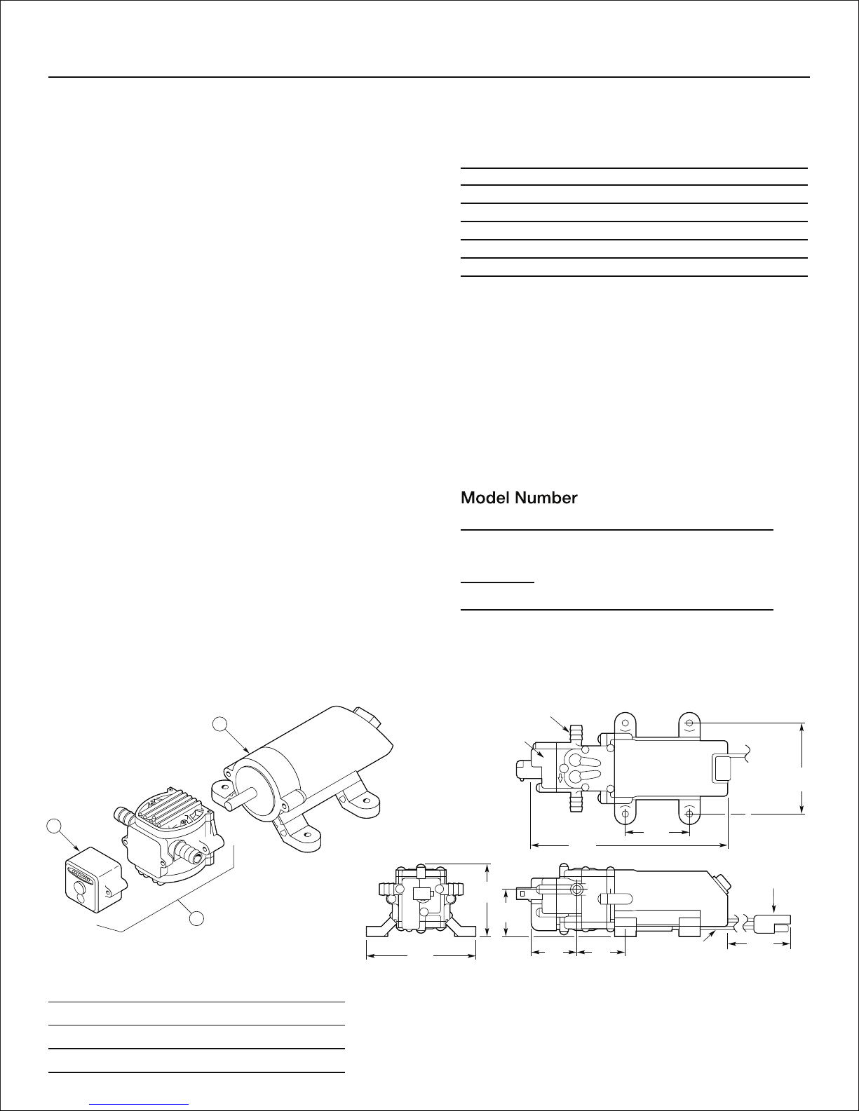
1 GPM quick disconnect pump
610007
11
12V 5AH/20HR battery size 6FM5
610008
1
2
EL 14 QD P Quick Disconnect Fitting
61002423
Retractable Handle Assembly610006
14
Suction Hose Assembly
610025
15
W 40650 S Strainer Washer
610023
1
6
Pinch Clamp
610022
47
#8 x 3/4" PH TEK Screw
60019928
Back Panel
610002
1
9
Economy Wand Assembly
610012
1
10
Wiring Harness
610010
111
12V DC 500 mA Battery Charger
610009
112
10
1
5
6
3
3
2
9
4
8
7
11 Wiring Harness (Not Shown)
12 Battery Charger (Not Shown)
Strainer should be periodically checked
and cleared of any forign debris
— PUMP, HOSE & BATTERY ASSEMBLY
PRECISION SPRAY EQUIPMENT, a divison of Green Leaf, Inc. 9490 N BALDWIN ST FONTANET, IN 47851 www.grnleafinc.com
a division of Green Leaf, Inc
®
PRECISION SPRAY EQUIPMENT
PSE
Parts List
DESCRIPTIONPART NUMBERQTY
ITEM
5 Gallon Tank
610000
11
5 Gallon Tank Lid
610001
1
2
Back Panel
610002
1
3
Charger Panel Door
6100031
4
φ3/8" Axel Mounting Bracket
61000525
Wheel
61000426
φ3/8" x 14 7/8" Axel
610013
17
φ3/8 Cap Nut Black
61001928
1/4-20 x 1/2" Pan Head Screw
61001769
Wand Clip600151210
Wand Clip Screw
6001522
11
1
4
9
2
10
11
6
8
9
7
5
3
Strainer location
— REAR COMPARTMENT ASSEMBLY
PRECISION SPRAY EQUIPMENT, a divison of Green Leaf, Inc. 9490 N BALDWIN ST FONTANET, IN 47851 www.grnleafinc.com
a division of Green Leaf, Inc
®
PRECISION SPRAY EQUIPMENT
PSE
PowerFLO
™
2200 Series
3
1
2
Dimensions Inches (mm)
Specifications
Motor
Type: 12 VDC, permanent magnet, thermally protected,
splashproof
Leads:
2200-2 Model: 18 AWG, 4.5” long w 2-pin connector
Duty Cycle: Intermittent
Pump
Type: 2-chamber positive displacement, self priming,
capable of being run dry
Liquid Temperature: 110°F (43°C) Max.
Priming Capabilities: 4 feet (1.2 m) suction lift
Max Pressure: 40 PSI (2.8 bar)
Pressure Demand Switch:
Shut-Off: 40 ±5 PSI (2.8 ±0.3 bar) factory setting
Turn-On: 25 ±5 PSI (1.7 ±0.3 bar) factory setting
Inlet/Outlet Ports: Quick Disconnect
Weight
1.25 lbs (0.57 kg)
Performance
Materials of Construction
Motor Housing: Nylon 6/6
Pump Housing: Polypropylene
Valves: Viton
Diaphragm: Santoprene
Fasteners: Stainless steel and zinc plated
Pressure/Flow/Amp Draw
PSI Bar GPM LPM Amps
0-3 0.2 1.00 3.7 1.5
10 0.7 0.85 3.1 1.9
20 1.4 0.71 2.6 2.1
30 2.1 0.61 2.3 2.4
40 2.8 0.42 1.6 2.6
Parts List
Ref Part
#Description Number
1Switch Asssembly 5157201
2
Pump Head w Switch Asssembly
5275064
3
Motor with connector, no switch
P39-045B
2.25
(57)
6.89
(175)
1.66
(42)
2.55
(65)
3.94
(100)
1.58
(40)
1.73
(44)
4.5
(114)
Pressure
Demand Switch
3.19
(81)
Quick Disconnect Ports
2-Pin Connector
18 AWG Leadwires:
Blk – Negative
Red – Positive
Ordering
Item # Description
2200-201
1 GPM Demand Pump, Viton Valves,
Santoprene Diaphragm, 40
PSI, Quick Disconect Ports
2-pin molded connector

12 Volt DC Motor-Driven Diaphragm Pumps
Operation Precautions
1. Do not operate pump in an explosive environment.
Arcing from the motor brushes, switch or excessive heat from an improperly cycled motor may cause an explosion.
2.
3Do not assume fluid compatibility. If the fluid is improperly matched to the pumps’ elastomers, a leak may occur.
Do not pump gasoline or other flammable liquids.
4. Intermittent duty is defined as operation and/or frequent starting within a period of time that would cause the motor to
reach its maximum thermal limits.
Once the maximum is obtained, the motor must be allowed to return to ambient temperature before resuming operation.
Troubleshooting Guide
Problem/Causes and Remedies
Pump will not Start
Check:
•Correct voltage (+10%) and electrical connections
•Fuse or breaker
•Pressure switch operation and correct voltage at
switch
•Rectifier or motor for open or grounded circuit
•Locked drive assembly
Pump will not Prime (No discharge with motor running)
Check:
•Debris in strainer
•Restriction (kinks) in inlet/outlet tubes
•Debris or swelling in inlet/outlet valves
Pump will not Shut Off (Output line closed and no leaks)
Check:
•Air trapped in outlet line or pump head
•Correct voltage to pump
•Debris in pump inlet/outlet valves
•Loose drive assembly or pump head screws
•Pressure switch operations/adjustments
Leaks from Pump Head or Switch
Check:
•Loose screws at switch or pump head
•Switch diaphragm ruptured or pinched
•Punctured diaphragm if fluid is present
* Important return safety instructions:
When you return your pump for warranty or repair,
you must always do the following:
1. Flush chemical residue from the pump
(best done in the field).
2.
Tag pump with type of chemicals having been sprayed.
3. Include complete description of operation problem,
such as how pump was used, symptoms of
malfunction, etc.
Since pumps can contain residues of toxic chemicals
these steps are necessary to protect all the people
who handle return shipments, and to help pinpoint the
reason for the breakdown.
PRECISION SPRAY EQUIPMENT, a divison of Green Leaf, Inc. 9490 N BALDWIN ST FONTANET, IN 47851 www.grnleafinc.com
a division of Green Leaf, Inc
®
PRECISION SPRAY EQUIPMENT
PSE
Table of contents
Popular Paint Sprayer manuals by other brands

micronAir
micronAir AU8000 Operator's manual

Fast
Fast UT3P Operation and maintenance manual

Wylie
Wylie Defender 3 Pt Sprayer Operator's & parts manual

DeVilbiss
DeVilbiss JGP-503 CONVENTIONAL Service bulletin

Parkside
Parkside PDFP 500 C3 Translation of the original instructions

AG SPRAY
AG SPRAY TR500PHS-S owner's manual


