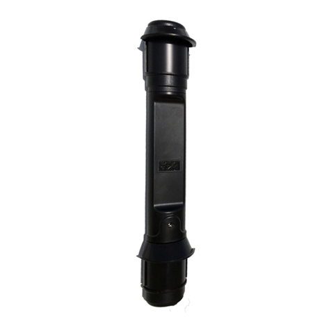
PSG Dover Wilden SafeGuard Instruction Manual

EOM
ENGINEERING OPERATION
&
MAINTENANCE
Wilden SafeGuard™
Remote Monitoring and Alert System
WIL-19230-E-01
Where Innovation Flows

WIL-19230-E-01 Wilden®
2
Contents
Section 1: Precautions - Read First! 4
Section 2: How It Works 5
Section 3: Dimensional Drawings 6
Section 4: Installation
7
Section 5: Maintenance
11
Section 6: Troubleshooting
12
Section 7: Exploded View and Parts List 13

WIL-19230-E-01 Wilden®
3
Copyright
Copyright 2020 PSG®, a Dover Company. All rights reserved.
PSG reserves the right to modify the information and illustrations in this document without prior notice. The
product described in this document is furnished under a license agreement or nondisclosure agreement. No
part of this document may be reproduced, stored in a retrieval system, or transmitted in any form or any
means electronic or mechanical, including photocopying and recording, without the written permission of PSG,
a Dover Company, except as described by the terms of those agreements.
This is a non-contractual document. 04-2020.
Trademarks
PSG and the PSG logo are registered trademarks of PSG. Wilden® is a registered trademark of PSG
California LLC. Wilden SafeGuard™ is a trademark of PSG.
All trademarks, names, logos and service marks (collectively "trademarks") in this document are registered
and unregistered trademarks of their respective owners. Nothing contained in this document should be
construed as granting any license or right to use any trademark without the prior written permission of the
trademark owner.
Warranty
Wilden warrants to the original purchaser that your Wilden SafeGuard Remote Monitoring and Alert System
Edge Device and Gateway Node shall be free from defects in material and workmanship under normal use for
a period of one (1) year from date of shipment. Due to the varied ways that product(s) can be accessed and/or
configured during use, battery life is excluded from warranty. If you have an active contract and damage
product during use, please contact Wilden as there are opportunities to replace the equipment at a reduced
rate.
Wilden warrants to the original purchaser that your Wilden SafeGuard Remote Monitoring and Alert System
Leak Detection Sensor shall be free from defects in material and workmanship under normal use for a period
of five (5) years from the date of installation or six (6) years from date of manufacture, whichever comes first.
To register your Wilden SafeGuard Remote Monitoring and Alert System for warranty, please visit
https://www.psgdover.com/wilden/support/warranty-registration.
Data Security and Privacy Policy
The use of Wilden SafeGuard Remote Monitoring and Alert System requires agreement to Wilden’s Privacy
Policy, End User License Agreement, and Master SaaS Agreement. For copies of these policies, please visit
www.psgdover.com/wilden/products/performance-monitoring-and-alert-system/wilden-safeguard
Certifications
IP66 Certified

WIL-19230-E-01 Wilden®
4
The following outlined Precautions are for the
Wilden SafeGuard equipment only. For specific
Precautions on your pump, please refer to your
pump model manual.
WARNING: Always wear safety glasses when
operating a pump to avoid eye injury. If diaphragm
rupture occurs, materialbeing pumped maybe forced
out of the air exhaust.
CAUTION: Before attempting any maintenance or repair,
disconnect the compressed air line to the pump and allow all
air pressure to bleed from the pump. Disconnect all intake,
discharge, and air lines. Drain the pump byturning it upside
down and allowing any fluid to flow into a suitable container.
Be aware of any hazardous effects of contact with your
process fluid.
WARNING: For more details on Cautions and Warnings
for the pump that the SafeGuard system is to be installed,
or is installed on, please see the associated pump model
manual. All pump manuals are available on
www.wildenpump.com Download Library.
CAUTION: When removing the end cap using compressed
air, the air valve end cap may come out with considerable
force. Hand protection such as padded glove or rag should
be used to capture the end cap.
CAUTION: The SafeGuard Gateway Node must be
mounted within 150 feet of the installed SafeGuard Edge
Devices to ensure proper operation. Impediments between
the pump, Edge Device and Gateway Node can cause this
range to vary. The SafeGuard Gateway Node can handle up
to 10 SafeGuard Edge Devices.
WARNING: Changes or modifications which are not expressly
approved by Wilden could void the authority to operate the
equipment.
NOTE: SafeGuard complies with Part 15 of the FCC rules.
Operation is subject to the following two conditions: (1) this device
may not cause harmful interference and (2) this device must
accept any interference received, including interference that may
cause undesired operation.
NOTE: The SafeGuard Gateway Node contains licensee-
exempt transmitter(s)/receiver(s) that comply with Innovation,
Science and Economic Development Canada’s licensee-
exempt RSS(s). Operation is subject to the following two
conditions: (1) this device may not cause interference and (2)
this device must accept any interference, including that may
cause undesired operation of the device.
NOTE: SafeGuard has been evaluated for RF Exposure
per RSS-102 and is in compliance with the limits specified
by Health Canada Safety Code 6. The system must be
installed at a minimum separation distance from the
antenna to a general bystander of 8 inches (20 cm) to
maintain compliance with the General Population limits.
NOTE: SafeGuard is not an ATEX Certified product and
using the equipment on an ATEX compliant pump, voids
the ATEX Certification.
PRECAUTIONS – READ FIRST!
Section 1

WIL-19230-E-01 Wilden®
5
Wilden SafeGuard System Options
Feature
Tier 1
Basic package to monitor
pump performance
Tier 2
Advanced package combining pump
performance monitoring and real-time
leak detection
Edge Device
X
X
Gateway Node
X
X
Web UI and Phone Application
X
X
Stroke Count
X
X
Stroke Rate
X
X
Leak Detection
X
24/7 Real-Time Alerts
X
X
Abnormal Operation Alert
X
X
Pump Mounting Kit
End Cap
End Cap and Junction Box (J-Box)
How it Works
Wilden SafeGuard is designed to monitor Wilden AODD pumps’ health and performance. It is composed of a single battery-powered
sensor (Edge Device) mounted directly onto the pump which communicates to a sensor reader (Gateway Node). The Gateway Node,
which can connect up to 10 Edge Devices/Pumps, operates as an encryption router, securely transmitting the data from all pumps to the
Cloud. The Tier 2 system option includes an additional real-time leak detection sensor. The Leak Detection Sensor indicates a leak when
fluid fills the sensor housing.
The data (stroke count, stroke rate, leak detection) are collected into the Gateway Node and transferred to the Cloud (via cellular data
service) to be analyzed. The data is displayed and summarized on Wilden’s SafeGuard Software user interface where you can view the
status of your whole fleet of connected pumps down to the details of a single pump.
HOW IT WORKS
Section 2

WIL-19230-E-01 Wilden®
6
Tier 1
Tier 2
DIMENSIONS
DIMENSION
ITEM
1″PUMP
1-1/2″PUMP
2″PUMP
3″PUMP
A
86.4 mm (3.4″)
63.5 mm (2.5″)
63.5 mm (2.5″)
63.5 mm (2.5″)
ITEM 1” PUMP 1-1/2” PUMP 2” PUMP 3” PUMP
A
109.2 mm (4.3″)
101.6 mm (4.0″)
101.6 mm (4.0″)
101.6 mm (4.0″)
B
315 mm (12.4″)
358.1 mm (14.1″)
515.6 mm (20.3″)
515.6 mm (20.3″)
DIMENSIONAL DRAWING
Section 3
Note: Dimensional Drawing of Tier 2 represented on a PS420 Metal Pump Model.
For full dimensions of your specific pump model, refer to the pump manual.
Note: Dimensional Drawing of Tier 1 represented on a PS420 Metal Pump Model.
For full dimensions of your specific pump model, refer to the pump manual.

WIL-19230-E-01 Wilden®
7
Edge Device and
Leak Detection
Tools Required:
•
3/16″Hex Wrench
•
PTFE Tape
•
Wilden Air System Grease
CAUTION: Before attempting any maintenance or repair, disconnect the
compressed air line to the pump and allow all air pressure to bleed from the pump.
Disconnect all intake, discharge, and air lines. Drain the pump by turning it upside
down and allowing any fluid to flow into a suitable container. Be aware of any
hazardous effects of contact with your process fluid.
NOTE: The model pictured in this section is an aluminum PS420 38 mm (1-1/2″)
pump. Your specific pump model may vary from the configuration shown.
However, the pump disassembly procedure willbe the same.
NOTE: Replace worn parts with genuine Wilden parts for reliable performance.
Step 1
Using a 3/16" Hex Wrench, remove the top
two air valve bolts.
Step 2
Once the top two air bolts are removed,
remove the top air valve end cap by simply
lifting up on the end cap.
Step 3
For Tier 1 Only – Take the Edge Device and
mounting end cap, add grease to the O-Ring
and install it on the top of the air valve as the
end cap replacement.
For Tier 2 Only – Take the Edge Device and
J-Box, add grease to the O-Ring and install it
in the top of the air valve as the end cap
replacement.
NOTE For Tier 2 Only: Make sure the
single J-Box port is aligned with the
exhaust of the air valve, which contains
the Wilden name and part number.
INSTALLATION
Section 4

WIL-19230-E-01 Wilden®
8
Step 4
Using the 3/16" Hex Wrench, re-install the
top two air valve bolts, securing the Edge
Device to the pump. Be sure to not tighten
the bolts beyond the maximum torque
specifications outlined in your pump’s
manual. For Pro-Flo SHIFT it’s
13.6 N•m (120 in-lb).
Step 5
Fore Tier 2 Only – Remove the muffler
from the muffler plate.
Step 6
For Tier 2 Only – Install the leak detection
unit into the muffler plate with the appropriate
adaptors for the size of your pump. Refer to
the parts list on page 14 for the adaptor
appropriate for your pump. Hand tighten until
the last full turn ends with the leak detection
cable facing up.
Step 7
For Tier 2 Only – Install the muffler into the
leak detection unit with the appropriate
adaptor based on your pump size, tightening
by hand. Identify the appropriate adaptors for
your pump size in the parts listing on page
14.
Step 8
For Tier 2 Only – Install the leak detection
cable into the front port of the J-Box.
Step 9
Remove the rubber seal from the Edge Device.
INSTALLATION

WIL-19230-E-01 Wilden®
9
Step 10
Unscrew the top of the Edge Device by
hand to remove the cap.
Step 11
Insert (2) AA batteries into the battery slots.
Be sure to leave the tray empty where it’s
marked “Leave Empty”.
A light will flash blue when powered.
Reinstall the Edge Device cap and rubber
seal.
The Wilden SafeGuard Installation is
Complete.
INSTALLATION

WIL-19230-E-01 Wilden®
10
Gateway Node
Tools Required:
•9/64″ Allen Wrench
•(4) #8-32 x 1″ Screws
Installation
1. It is recommended to mount the Gateway Node at least 3
ft. or more from the ground. Additionally, minimize
obstruction between the Gateway Node and Edge Device.
2. Use the (4) #8-32 x 1″ Screws and 9/16″ Allen Wrench to
secure the Gateway Node to the monitored equipment.
Use the mounting guide for measurement reference.
3. There is no importance to the orientation. Once secured,
installation is complete.
4. Plug in the power adapter, set the antenna facing up
(vertically) and your Gateway Node should now be
installed.
Technical Specifications
The following outlines the technical specifications of the Gateway
Node:
•Maximum Number of Paired Edge Devices: 10
•Range: Up to 150 ft.
•Power Source: 9-24 VDC Powered by External DC Supply
•Communication:
o4G LTE Cellular Cloud Connectivity
o900MHz RF Star-Network Configuration
for Multiple Pumps Connectivity
oBLE
oGPS
•Build
oIP66 EPDM Rubber Sleeve Protected 20% Glass Reinforced
Polypropylene Enclosure
•Standards
oFCC Part 15
oRoHS Comply
•Environmental Conditions
oTemperature: -30°C – 70°C (-22°F – 158°F)
INSTALLATION

WIL-19230-E-01 Wilden®
11
Edge Device
The batteries within the Edge Device are expected
to last up to 1 year. The Edge Device requires (2)
AA batteries. When the batteries need to be
replaced, follow Steps 9 through 11 of the
installation process:
1. Remove the rubber seal from the Edge
Device
2. Unscrew the top of the Edge Device by
hand to remove the cap
3. Take the old batteries out, insert the
(2) new AA batteries
4. A light will flash blue when powered.
Reinstall the Edge Device cap and
rubber seal
Edge Device LED Light Indicators
The Edge Device has two LED Light indicators. One
to indicate its on/off and paired/not paired status
and one to indicate a warning or fault.
LED Light #1
On/Off – Edge Device has Power
Blinks every 5 seconds
Single Blink – Edge Device is Paired
Double Blink – Edge Device is Not Paired
LED Light #2
Mirrors Indicators on Pump Dashboard
Single Blink – Warning
Double Blink – Fault
Leak Detection
In the event that a leak is detected via the Leak
Detection Sensor, the product could potentially
contaminate the float switch and the float switch
may need to be replaced. To replace the Leak
Detection Sensor float switch, take the following
actions:
1. Disconnect the Leak Detection Sensor
from the J-Box
2. Remove the two screws from the top of
the Leak Detection Sensor and remove
the cap, the float switch will be attached
to the cap
3. Insert the replacement float switch and
cap and secure with the screws
4. If needed, drain and clean the Leak
Detection Sensor by unscrewing the
screws on the ears of the Leak
Detection Sensor and gently pulling
down on the Detection well.
MAINTENANCE
Section 5

WIL-19230-E-01 Wilden®
12
Edge Device
LED LIGHT INDICATOR NOT BLINKING
1. Remove rubber sleeve and top to confirm the battery
pack is connected to the Edge Device using the
appropriate terminal. (Step 9-11 in Section 4 of this
manual)
2. Confirm the cable extending from the battery pack is
not cut, broken, or damaged.
3. Disconnect battery pack from the terminal and
reconnect. The LED should light up immediately.
4. If Step 3 above does not work, connect a new battery
pack to the appropriate terminal. The LED should light
up immediately.
5. If this does not fix the problem, please contact
customer service.
Leak Detection
FALSE ALARMS
1. False leak detections may be caused by condensate,
frozen condensate, or other debris collecting in the
detection well and activating the float sensor. To fix
this, remove the detection well by unscrewing the two
screws on the ears of the leak detector and gently
pulling down on the detection well.
2. Remove any debris that may have
accumulated and replace the well.
TESTING THE FLOAT SENSOR
1. To test the float sensor, remove the detection
well by removing the screws on the ears of
the leak detector and gently pulling down on
the detection well. The float sensor will stay
with the main part of the leak detector.
2. Gently push up on the foam cylinder float and
hold it there.
3. Check the user interface on
www.wildensafeguard.com to see if the leak
indicator turns on. This may take a few
seconds.
4. If it does not, check the connection between
the leak detector cable and the J-Box. If this
does not fix the problem, please contact
customer service.
Gateway Node
EXTERNAL DC POWER SUPPLY CONNECTED,
BUT LED LIGHT OFF
1. Confirm the cable extending from the Gateway Node
to the power outlet is not cut, broken, or damaged.
2. Confirm the outlet being used is supplying voltage.
3. If this does not fix the problem, please contact
customer service.
TROUBLESHOOTING
Section 6

WIL-19230-E-01 Wilden®
13
Tier 1 and 2 – 1″
EXPLODED VIEW
25 mm (1″) Pro-Flo SHIFT Series Bolted Metal Pump (PS220) represented in the exploded view for Tier 1 and Tier 2 (1″) Option
Tier 1 and 2 – 1-1/2″ to 3″
EXPLODED VIEW
38 mm (1-1/2″) Pro-Flo SHIFT Series Bolted Metal Pump (PS420) represented in the exploded view for Tier 1 and Tier 2 (1-1/2″to 3″) Options
EXPLODED VIEW AND PARTS LIST
Section 7
*

WIL-19230-E-01 Wilden®
14
Item Description Qty. Tier 1 – 1″ Tier 2 – 1″ Tier 1 – 1-1/2″ to 3″ Tier 2 – 1-1/2″ to 3″
Wilden SafeGuard Components
A
SafeGuard Edge Device
1
02-8290-99
02-8294-99
04-8292-99
04-8296-99
B
Leak Detector
1
N/A
02-8016-01
N/A
04-8016-01
*
Pump Side Adaptor (Coupling Leak Detection)
1
N/A
04-7425-01
N/A
04-7505-01
*
Pump Side Adaptor (Bushing, Reducer)
1
N/A
N/A
N/A
04-6959-08
*
Muffler Side Adaptor
1
N/A
04-6950-01
N/A
04-7426-01
**
Gateway Node (**not shown in exploded view)
1
99-8254-99
Note: Not all parts are available to order outside the system
EXPLODED VIEW AND PARTS LIST

WIL-19230-E-01 Wilden®
Notes

WIL-19230-E-01 Wilden®
PSG
22069 Van Buren Street
Grand Terrace, CA 92313-5651 USA
P: +1 (909) 422-1730 • F: +1 (909) 783-3440
psgdover.com
Where Innovation Flows
PSG®reserves the right to modify the information and illustrations contained in this document without prior notice. This is a non-contractual document. 04-2020
Table of contents
Popular Security System manuals by other brands
Federal Signal Corporation
Federal Signal Corporation PA4000 Installation, operation and service instructions
GE
GE TX-7201-05-1 quick start guide

Siemens
Siemens FS20 Commissioning, Maintenance, Troubleshooting

ADEMCO
ADEMCO Vista-10 installation instructions
Lorex
Lorex D881 Series quick start guide

Evolveo
Evolveo Alarmex Pro ACSALMBTZ manual
