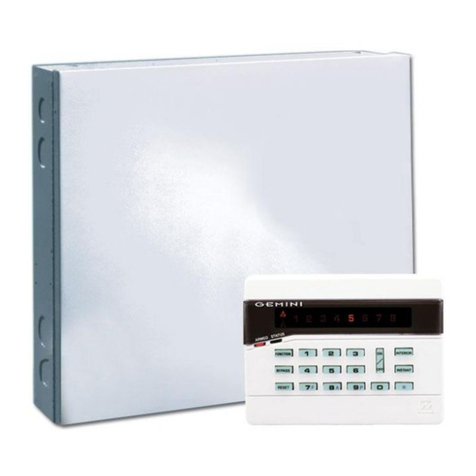
Gemini GEM-P800 User manual

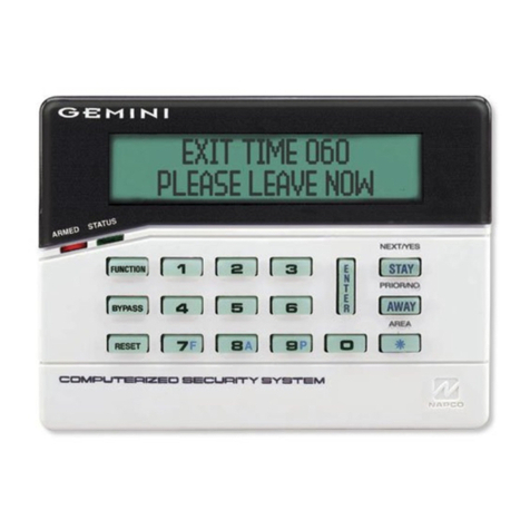
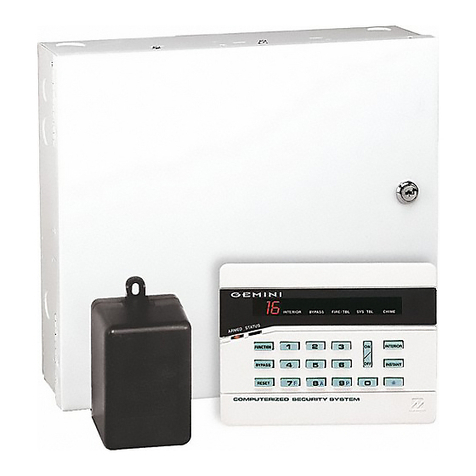
GEM-P800
Installation Instructions
Control Panel/Communicator
WI850A 8/97© NAPCO 1997
®
Wi850a
page 1 Tuesday, September 16, 1997 08:01

2
WI850A GEM-P800 Installation Instructions
*HQHUDO ,QIRUPDWLRQ
The GEMINI GEM-P800 control panel provides up to
6 hardwired/wireless zones, a 2-wire fire zone and 2
wireless only zones. Up to eight 4-digit user codes
can be programmed. Ambush, when selected, uses
User 8 code as an Ambush code.
The GEM-P800 is wireless ready. When used with a
GEM-RECV-XP8 receiver, the control panel can sup-
port up to 8 wireless zones, 4 wireless smoke detec-
tors and 4 Keyfobs.
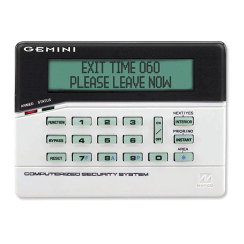
The GEM-RP8 keypad provides complete control of
the GEM-P800 control panel. Information on system
status, bypassed zones, system troubles etc. can be
viewed at the keypad.
The control panel can be easily and quickly pro-
grammed from the keypad. The panel can also be
locally or remotely downloaded using PCD3000 soft-
ware and a PCI 2000/3000 interface or PCL2000A
local Download cable. See Downloading Section (pg.
5) for more information.
*(03 )HDWXUHV
Control Panel
• 8 Zones
• 2-wire Fire Zone
• 3 Keypad Panics
• Wireless Ready
• Bell Supervision
• Line Cut Detection
• Answering Machine Override (Second Call)
• 50 Event Log
Communicator
• 2 Telephone Numbers
• Backup Reporting
• Pager Format
• Point ID Format
• Individually Report 8 Users
• Opening after Alarm Report (Cancel Code)
For Technical Assistance, Contact the NAPCO Toll Free Helpline
(800) 645-9440
NAPCO Security Systems, Inc.
333 Bayview Avenue
z
Amityville, New York 11701
For Sales and Repairs, call Toll Free: (800) 645-9445
7DEOH RI &RQWHQWV
General Information..........................................2
GEM-P800 Features.........................................2
Specifications...................................................3
UL Compatible Smoke Detectors......................4
Listings and Approvals .....................................4
Ordering Information ........................................4
Optional Accessories........................................4
Programming the Panel....................................5
Installation........................................................6
Wiring...............................................................6
Keypad Operation ............................................7
Panel Operation ...............................................8
Bypassing ........................................................9
User Program Mode.........................................10
GEM-P800 Commands ....................................10
Dealer Commands ..........................................11
Wireless Operation (Signal Strength) .............12
Zone Features..................................................13
System Times ..................................................14
System Features..............................................15
Telephone Number 1 Programming..................16
Backup Telephone Programming .....................17
Pager Programming .........................................18
Telephone Number 3 Programming..................18
Report Codes...................................................19
Enhanced Communicator Features..................19
Wireless...........................................................20
Downloading.....................................................21
Dealer Programming ........................................22
System Troubles ..............................................23
Troubleshooting................................................25
GEM-P800 WIRING DIAGRAM........................27
Wi850a
page 2 Tuesday, September 16, 1997 08:01

3
6SHFLILFDWLRQV
&XUUHQW 9ROWDJH 5DWLQJV
Alarm Output ---------------------------Burg: 12 VDC, 2A (max.)
Fire: 12 VDC, 65 mA
Output Current Limiting --------------Burg/Fire:2.25 A
AUX Power: 750 mA
Combined Standby Current:--------350 mA maximum
(Remote PWR, AUX Output, PGM)
4 Hour Standby:------------------------350 mA Standby Current
Bell Output 65 mA
(Using Rechargeable 12 VDC 4 AH BATTERY, minimal requirement)
24 Hour Standby:----------------------120 mA Standby Current
Bell Output 95 mA
(Using Rechargeable 12 VDC 7 AH BATTERY, Optional)
7UDQVIRUPHU DQG %DWWHU\
Required Transformer: --------------NAPCO TRF12 OR
BASLER 16.5 VAC 20VA
Required Battery: ---------------------12V 4 AH Rechargeable
Change Battery every 5 years or as required
Maximum Charging Current: -------165 mA
Maximum Input Current:-------------2.58 A
/RRS &KDUDFWHULVWLFV
Loop Voltage: ------------------------- 5 Volts
Loop Current :-------------------------- Zones 1, 2, 3: 0.9 mA
Zones 4, 5, 6: 0.5 mA
Loop Resistance: --------------------- 100Ω per zone (max.)
'HYLFH 6SHFLILFDWLRQV
Max # keypads:------------------------ 4, GEM-RP8 current = 65 mA
Max # of receivers: ------------------- 2, GEM-RECV-XP8
current = 65 mA each
Max # of compatible
2-wire smoke detectors : ----------- 10
Max Keypad wire length : --------- 1000’ total wire length
0LVFHOODQHRXV
Housing Dimensions : -------------- 11" x 121/8"x 3"
(28 x 30.8 x 7.6) HxWxD
Shipping Weight: -------------------- GEM-P800 5.5 lbs.
Operating Temperature: ------------ 0-49ºC (32-120°F)
Wi850a
page 3 Tuesday, September 16, 1997 08:01

4
WI850A GEM-P800 Installation Instructions
Mfg 4-Wire
Smoke Detector 2-Wire
Smoke Detector Smoke Detector
Base
Sentrol 449AT
449C
449CRT
449CST
449CSRT
449CSRH
449CSST
449CLT
449CSLT
449CTE
741U
742U
712U
722U
732U
711U
721U
721UT
731U 701U
702U
702RE
702RU
System
Sensor 1112
2112 2112T
2112TSRB 2100
2100T 1100
8 zone Control Panel with 2-wire fire
Ke
y
pad
Zone Doublin
g
Resistors (2.2K & 3.9K)
Operatin
g
Instructions GEM-P800
Pro
g
rammin
g
Instructions GEM-P800
GEM-P800
GEM-RP8
ZDR
OI219
WI851
2UGHULQJ ,QIRUPDWLRQ
2SWLRQDO $FFHVVRULHV
*Wireless Receiver
Window/Door Transmitter
Keyfob Transmitter
Wireless Smoke Detector
Wireless PIR
Wireless Dual-Technology Sensor
Wireless Glass-Break Detector
Relay Board
Audio Verification Module
Downloading Software for IBM PC Compatibles
Software with Interface for IBM PC Compatibles
Local Download cable
GEM-RECV-XP8:
GEM-TRANS2
GEM-KEYF:
GEM-SMK:
GEM-PIR:
GEM-DT:
GEM-GB:
RB1000
Veriphone:
PCD3000:
PCI2000/3000:
PCL2000A
/LVWLQJV DQG $SSURYDOV
UL HOUSEHOLD FIRE AND BURGLARY WARNING SYSTEM CONTROL UNIT
STANDARDS # 1023, 985
VERIFIED TO COMPLY WITH F.C.C. PART 15 AS CLASS B : DIGITAL DEVICE
(XURSHDQ (0& 5HJXODWLRQV &( &HUWLILFDWLRQ
HARMONIZED STANDARDS: EN50081-1 and EN50082-1
EC DIRECTIVES: 89/336/EEC, Electromagnetic Compatibility Directive
8/ &RPSDWLEOH 6PRNH 'HWHFWRUV
GEM-P800 Compatible Smoke Detectors
*Supports up to 8 zones, 4 Key Fobs, 4 Smoke Detectors
Wi850a
page 4 Tuesday, September 16, 1997 08:01

5
3URJUDPPLQJ WKH 3DQHO
Refer to GEM-P800 Programming Instructions (WI851)
Defaulting the Panel
1. Remove power from the panel.
2. Remove all wirin
g
from terminal 15 (PGM)
and terminal 3.
3. Connect terminal 15 (PGM) to terminal 3.
4. Apply power to the GEM-P800 control panel.
5. After a few seconds the ARMED, READY and
SYSTEM TROUBLE LEDs will flash.
6. The keypad will beep 3 times indicating the
panel default values have been loaded.
7. Remove wiring between terminal 15 (PGM)
and terminal 3.
8. Re-install original wiring for terminal 15 (PGM)
and terminal 3.
Keypad Programming
Refer to WI851 for information on keypad pro-
gramming.
Downloading
The GEM-P800 panel can be download/up-
loaded with PCD3000 software using the Ring
Method, Answering Machine Override (Second
Call) or
Method of downloading. The
panel can also be automatically downloaded/up-
loaded using PCD2000 Software running
PCPreset. For Site Initiated Downloaded, see
Auto Download ID Number
[93].
Local Downloading
Wire as shown in Figure 1. Use the power up or
method of establishing a connection. The
power up method is recommended if the panel is
attempting to report.
Remote Downloading
Wire as shown in Figure 2. The panel can
be remotely download/uploaded using any
one of the following methods:
1. The
method
2. Call-in method
3. Answering Machine Override (Second
Call)
4. Site-Initiated (PCPreset &
)
5. Automatic Downloading (Using PCPreset)
PGM
(-)
+12 -13 14 15 16 17 18 19
GREEN TIP RING
PHONE
PCL2000A
GREEN
RED
MODEM
FIGURE 1LOCAL DOWNLOAD
TIP RING
TELCO
MODEM
J1
TO COMPUTER
J3
LOCAL
TO
PCI2000
J2
TO EXTERNAL
MODEM
J4
TELCO J5 LINE
OUT TO
TELCO
FIGURE 2REMOTE DOWNLOAD
PGM
(-)
+12 -13 14 15 16 17 18 19
+PWR GND GREEN
PHONETELCO
GREEN
RED
GEM-P800 Panel at the site
RINGTIP RING
RJ31X
TIP
GRY
BRN
GND+PWR
BLACKRED
NOTE:
Any programming in
Dealer Options 1
[96] and
Dealer
Options 2
[97] will not be defaulted. If
Dealer Code
Lockout
has been programmed the panel will not default
the Dealer Code.
Wi850a
page 5 Tuesday, September 16, 1997 08:01

6
WI850A GEM-P800 Installation Instructions
,QVWDOODWLRQ
Mounting the Panel
Mount the Panel close to an unswitched AC
source, a cold-water pipe ground, and a tele-
phone line connection.
Mounting the Keypad
A keypad should be located near an exit/entry
door. To remove the keypad from the backplate,
insert a small screwdriver into the slots at the
bottom of the keypad. Pull up on the screwdriver
to pop off the cover.
Up to 4 keypads can be connected on individual
wire runs with #22 AWG wire with a maximum
total cable length of 1000 feet. Each keypad
draws approximately 65 mA.
Typical Fire Installation
(Where permitted by local codes)
Install smoke detectors outside each sleeping
area and on each floor, including the basement.
Install the living room and basement smoke de-
tectors near the stairway of the next upper level.
For increased protection, additional detectors
should be installed in areas other than those
required, such as the dining room, bedrooms
and utility room. Heat detectors, rather than
smoke detectors, are recommended in
kitchens, attics, and garages due to conditions
that may result in false alarms and improper
operation.
Refer to NFPA Standard 74 (National Fire Pro-
tection Association, Batterymarch Park,
Quincy, MA 02269) for additional information,
including proper mounting methods.
:LULQJ
Grounding the Panel
Connect the control-panel EARTH GROUND
screw to a metal cold-water pipe. Do not use a
gas pipe, plastic pipe or AC ground connections.
Use at least #16 AWG wire. Connect a wire with
a ground lug crimped or soldered onto one end
and connect it to the EARTH GROUND screw in
the cabinet.
AC Power and Battery Wiring
Complete all wiring before connecting the battery
or AC Power. Do not plug the transformer into a
switched outlet.
Telephone Wiring
Wire as shown in the wiring diagram in the back
of this manual.
WARNING
The FCC restricts the use of this equipment on
certain telephone lines. Read the FCC state-
ment on the back of this manual to ensure
compliance.
FIGURE
3Typical Fire Installation
Keypad Wire Color Control Panel Terminal
RED 12 (+PWR)
BLACK 13 (GND)
GREEN 14 (GREEN)
TABLE 1 KEYPAD WIRING
Wi850a
page 6 Tuesday, September 16, 1997 08:01

7
Burglary Zone Wiring
NAPCO’s EZ Zone DoublingTM is simple. Each
terminal has 2 zones, use an E(2.2 K) type Zone
Doubling Resistor for the primary zone and a Z
(3.9 K) type Zone Doubling Resistor for the
secondary zone.
Wire zones as shown in the wiring diagram (pg.
27). All resistors must be installed, even if the
zone is not used. If required, unsupervised open
circuit devices may be used instead of closed
circuit devices. Program the zone as an
Open
Circuit Zone
[06] (Zone Doubling Resistor re-
quired). If necessary, use the voltage chart
below to verify proper voltages.
Fire Zone Wiring
Wire the Fire Zone as shown in the Wiring
Diagram in the back of this manual. An EOL
resistor must be installed, even if the Fire Zone
is not used.
PGM Wiring
The PGM is a switched negative output that is
activated depending on the programming op-
tion(s) that have been selected [08], [23] - [25].
Connect the device controlled by the PGM
between +PWR and the PGM terminal
(maximum load of 50 mA).
.H\SDG 2SHUDWLRQ
Keypad zone LEDs indicate zone status.
ARMED, STATUS and
SYSTEM LEDs pro-
vide system status. The keypad sounder pro-
vides feedback beeps for correct and incorrect
entries.
Keypad Sounder
3 QUICK BEEPS
Panel Armed (System ON)
Chime ON
Fault Find Mode ON
Keypad Sounder ON
Zone Bypassed
6 QUICK BEEPS
Panel Disarmed (System OFF)
Chime OFF
Fault Find Mode OFF
Keypad Sounder OFF
Zone Un-Bypassed
1 SECOND - STEADY TONE
Incorrect Code Entered
Invalid key entry
4 LONG BEEPS (PRIORITY CONDITION)
1. Entering an Arm Code with a faulted zone
(Not an Auto-Bypass Reentry Zone).
2. Entering an Arm Code when the Bell or
PGM is ON (Bell and PGM will turn OFF).
3. Arming with the Fire LED ON - reset re-
quired. Press the
key.
Terminals Primary Secondary
3&4 Zone 1 Zone 4
5&4 Zone 2 Zone 5
6&7 Zone 3 Zone 6
TABLE 2 EZ ZONE DOUBLINGTM
Fire Zone Normal 13.0V
Fire Trouble 13.8V
Fire 0.0 V
TABLE 4 VOLTAGE AT FIRE ZONE (Terminals 8&9)
Primary and Secondary zones normal 1.9 V
Secondary open 2.5 V
Primary open 3.2 V
Primary and Secondary open 5.0 V
Primary and Secondary shorted (Sys. Trbl 7-
Zone Trbl) 0.0 V
TABLE 3 VOLTAGE AT TERMINALS 3&4, 5&4, 6&7
Wi850a
page 7 Tuesday, September 16, 1997 08:01

8
WI850A GEM-P800 Installation Instructions
Keypad LEDs
ARMED LED DEFINITION
Armed ON
Instant Mode Rapid Flash
Zone in Alarm Flashing
STATUS LED DEFINITION
Ready to be Armed ON
Zone faulted OFF
TROUBLE LED DEFINITION
AC Failure Flashing
System Trouble(s) ON
FIRE LED DEFINITION
Fire Alarm Flashing
Fire Memory/*Fire Trbl ON
*See Note 1
AC LED DEFINITION
AC Present ON
AC Failure OFF
ZONE LED DEFINITION
Faulted Zone ON
Bypassed Zone Slow Flash
Zone in Alarm Flashing
3DQHO 2SHUDWLRQ
Arming (System ON)
Before arming the system close all protected
zones (unless programmed as Auto-Bypass
Reentry Zones). Enter a 4-digit Arm/Disarm
code, followed by the
key, the keypad will
provide a feedback beep for each key pressed.
If a valid Arm/Disarm code is entered, the
keypad will beep 3 times. If an incorrect Arm/
Disarm code is entered, the keypad will sound
a 1-second tone indicating an incorrect entry.
Arming without Entry Delay (Instant
Mode)
Enter the
key to eliminate the entry delay.
The ARMED LED will flash rapidly to indicate
the panel is in Instant Mode. If an Exit/Entry
Zone is tripped while the panel is in Instant
Mode the panel will go into alarm immediately.
Arming/Disarming with a Keyfob
The system can be armed by pressing the
key, and disarmed by pressing the
key on
the Keyfob. Zones programmed as
Exit/Entry
Follower Zones
can be bypassed when the
or
keys on the Keyfob have been pro-
grammed for
Interior
[81-84]. Zones pro-
grammed as Home
/Away with Delay Zones
can
be armed regardless of the state of the
Exit/
Entry Zones
when the
or
keys on the
Keyfob have been programmed for
Full Set
[81-84]. To arm the system with all zones pro-
tected press the
key. Press and hold the
or
key for 1.5s to fully set the system
(The LED on the Keyfob indicate the Keyfob has
transmitted the signal). Program
Keyfob/
Keyswitch Chirp
[23-4] for an audible indication
of system arming and disarming.
Arming/Disarming with a Keyswitch
The system can be armed/disarmed by using a
momentary Keyswitch wired to Zone 6.
Program
Keyfob/Keyswitch Chirp
[23-4] for an audible
indication of system arming and disarming.
Arming Instant with a Keyfob
The panel can be ARMED INSTANT when the
or
keys on the Keyfob have been
programmed for
Instant
[81-84]. To arm the
system with Instant protection press the
key, then press and hold the
or
key for
1.5s to arm the panel with INSTANT protection.
Disarming (System OFF)
After entering the premises through an Exit/Entry
Zone, the keypad will sound the Entry Delay
* If
Fire Trouble on Fire LED
[96-4] has been enabled, a steady
Fire LED will indicate Fire Trouble.
NOTE:
Faulted Keyswitch or silent 24 hour zone normally do not
display at the keypad. If a silent 24 hour zone or Keyswitch
is faulted at the time of arming the faulted zone will display
only while the priority sound is ON.
NOTE:
Wi850a
page 8 Tuesday, September 16, 1997 08:01

9
Tone. Enter a valid Arm/Disarm code, then
press
. If a valid Arm/Disarm code is entered,
the keypad will beep 6 times, indicating the panel
has been disarmed. The red Armed LED will go
out. If an incorrect Arm/Disarm Code is entered,
the keypad will sound a 1-second tone, indicating
incorrect entry. Press the
key and re-enter
the code.
Disarming after an Alarm (Alarm Memory)
The armed LED and the zone(s) that caused the
alarm will be be flashing. Disarm the panel. The
system is currently not detecting zone faults or
displaying system trouble. The zone(s) that
caused the alarm will continue to flash. The
STATUS and
SYSTEM TRBL LEDs are out
indicating:
The system is displaying Alarm Memory.
Press the
key to clear Alarm Memory.
%\SDVVLQJ
Automatic Bypassing
Home/Away with Delay Zones
This zone type has the following operation de-
pending on whether an
Exit/Entry Zone
has been
violated during the
Exit Delay
time.
Home
Exit/Entry Zone
is not violated
Zones selected as Home/Away with Delay
Zones
will be bypassed automatically.
Away with Delay
Exit/Entry Zone is violated
Zones selected as Home/Away with Delay
Zones
will have a fixed 20-second entry
delay when violated before an
Exit/Entry
Zone
.
Full Setting the System with Automatic
Bypassing - Home/Away with Delay
Zones
From the Keypad
Press
to return protection to
Home/Away with Delay Zones
that have
been automatically bypassed. Three min-
utes are allowed to walk through
Exit/Entry
and
Exit/Entry Follower Zones
.
Using A Keyfob (GEM-KF)
All zones in the system can be armed
regardless of the state of the
Exit/Entry
Zone
when arming with a Keyfob and using
an AUX key programmed as Full Set.
Press
and press and hold the
or
keys for 1.5s when leaving the
premises. All zones, including
Home/Away
Zones
are armed.
Bypassing a zone
Press the
key, then the zone number to be
bypassed. While the panel is DISARMED, the
bypassed zone LED will flash slowly; indicating
the zone has been bypassed. While the panel is
ARMED, the bypassed zones will only be dis-
played if the
Display Bypassed
[21-3] option has
been selected.
Unbypassing a zone (Disarmed only)
Press the
key then the number of the
zone to be unbypassed.
Group Bypass
Press the
key to Bypass all
Exit/Entry
Follower Zones
[02] or
Home/Away Zones
[01] (only if the system is programmed exclu-
sively for
Home/Away with Delay zones
).
.
Using A Keyfob (GEM-KF)
Hold the
or
key on the Keyfob to
Bypass all
Exit/Entry Follower Zones
[02] or
Home/Away Zones
[01] (only if the system is
programmed exclusively for
Home/Away
with Delay zones
).
8VHU 3URJUDP 0RGH
To prevent the loss of the User 1 Code, the panel
default program includes
User 1 Code Lockout
[96-2].
To change the User 1 Code from its default value
Wi850a
page 9 Tuesday, September 16, 1997 08:01

10
WI850A GEM-P800 Installation Instructions
of 1234, program the 4-digit User 1 Code through
Dealer Programming [95]. User 1 Arm/Disarm
code is also used to program User Codes 2 - 8.
By default, the User 1 code cannot be re-
programmed by the user.
If it is necessary to change the User 1 code, it
can be changed through downloading or Dealer
keypad programming. From Dealer Program
Mode, change the U
ser 1 Code Lockout
([96-2]
LED=OFF) to disabled.
Entering User Program Mode
1. Enter
2. Enter User 1 Code (
)
(Default)
3. Press
While in User Program Mode the Armed, Status
and
System Trouble LEDs will continue to
flash, follow the example below to program
User 2’s code to 1923.
User Mode Programming Example:
1. Press
, Zone 2 LED will Flash
2. Enter
, Zone 2 LED
will continue to flash until the 4th digit is
entered. The keypad will beep 4 times
confirming a valid entry (Zone LED steady).
Deleting a User Code
Press the number of the User to be deleted, the
zone LED will be flashing indicating that the
user has been selected. Press the
key,
the LED associated with the user will now be
OFF.
Exiting User Program Mode
To exit User Program Mode press the
key.
*(03 &RPPDQGV
User Commands
Bell Test
Enter this command to turn on the Bell, keypad
sounder and keypad LEDs for 2 seconds. The
battery is tested during a Bell Test, and auto-
matically every *24 hours to ensure proper bat-
tery operation under load. The Alarm output
requires a battery in order to supply the specified
output. If the battery cannot sustain the load, a
low battery indication will be displayed. A battery
test is also performed on power-up after a 3
minute delay.
*A battery test occurs every 4 hours when
Household Fire
[96-3] has been selected.
Easy Arm
Press this key to arm the panel. To disarm the
panel a valid Arm/Disarm code must be entered.
Requires
Easy Exit/Easy Arm [
21-2] to be en-
abled.
Interior
Enter this command to bypass all
Exit/Entry
Follower Zones
or
Home/Away Zones
(only if the
system is programmed exclusively for Home/
Away with Delay zones).
Instant
Enter this command before or after arming to
remove the entry delay on
Entry/Exit Zones
. The
keypad ARMED LED will flicker rapidly. Faulting
a
Exit/Entry Zone
will result in an immediate
alarm.
Chime ON/OFF
Enter this command to turn chime ON/OFF. The
ARMED, STATUS AND
SYSTEM TROUBLE
LED’s WILL FLASH.
ARMED
GEMINI
STATUS
1
A 1 is displayed indicating
User 1 Code is programmed
and 2-8 are blank.
Zone LED Meanin
g
OFF User Arm/Disarm Code not programmed
Flashin
g
User Arm/Code is currently being programmed
Stead
y
User Arm/Disarm Code has been programmed
TABLE 5 ZONE LED DEFINITION-USER PROGRAM MODE
Wi850a
page 10 Tuesday, September 16, 1997 08:01

11
Keypad will chime on any zone that has not been
selected as an
Exit/Entry Follower Zone
,
Home/
Away with Delay Zones,
or
24 Hour Zone
.
+ User 1 Code - User Program
Mode
Keypad Sleep Mode ON/OFF
Enter this command to turn the keypad sounder
ON/OFF. When the keypad is in Sleep mode all
keypad sounds will be silenced except for key-
pad feedback beeps and Keypad Sounder on
Alarm.
User Commands - Optional
Easy Exit
If enabled in Dealer programming, enter this
command while the panel is Armed to allow 3
minutes to exit the premises through
Exit/Entry
and
Exit/Entry Follower Zones
.
Access on PGM
If enabled in Dealer programming, enter this
command to activate the PGM output (Terminal
15) for 5 seconds.
'HDOHU &RPPDQGV
Download (Programming Re-
quired)
Establish a connection between the PCD phone
line and the Control Panel phone line. When
ready, tell the installer to arm, then disarm.
Then enter
in order to establish a
connection. Phone connection to installer will
go "dead" as downloader and panel connect.
Fault Find ON/OFF
Hardwired Zone Operation
Enter this command to turn Fault Find ON/OFF.
While in Fault Find mode, the loop response for
all zones will be set to the faster response of 40
ms. The keypad will beep for .25-seconds when
hardwired zones are faulted and for 1-second
when zones are restored.
:LUHOHVV 2SHUDWLRQ
6LJQDO 6WUHQJWK
While in Fault Find mode the keypad will pro-
vide an audible (Table 6) and visual (Figure 5)
indication of each transmitter’s signal strength.
The signal strength metering is based on a
scale of 4 to 10, with 4 being marginal and 10
being excellent.
The keypad will beep out a number, from 1-4,
corresponding to the signal strength of the
transmitter. See Table 6. Each beep is 1-
second long. The keypad will sound a short
beep for transmitters with signal strengths of 3
or less.
Signal Strength Logging Mode
The Signal Strength Logging Mode is a trou-
bleshooting tool which allows the collection of
signal strength information for all transmitters on
the system. Normally the Signal Strength of Su-
pervisory Signals are not logged; during Signal
Strength Logging Mode the signal strength infor-
mation for all supervisory signals received over a
two hour period will be saved to the LOG.
Local Activation
Enable [92-4=ON], this will initiate a two hour test
period where all supervisory signals will log sig-
nal strength information.
SIGNAL STRENGTH KEYPAD SOUNDER
3 or less .25S BEEP
4BEEP
5BEEP BEEP
6-7 BEEP BEEP BEEP
8-10 BEEP BEEP BEEP BEEP
TABLE 6 AUDIBLE SIGNAL STRENGTH INDICATION
Signal Strength = 8-10
Signal Strength = 6-7
Signal Strength = 4
Signal Strength = 5
1
12
123
1234
FIGURE 5VISUAL SIGNAL STRENGTH INDICATION
Wi850a
page 11 Tuesday, September 16, 1997 08:01

12
WI850A GEM-P800 Installation Instructions
Remote Activation
Using NAPCO’s Quickloader Software
(Version 3.26 or higher), follow the instruc-
tions below:
From the Status Screen
Press F6
Select Miscellaneous Control
Select Enable Signal Strength Logging
Uploading Signal Strength Information
from the Log
After approximately (2) two hours, re-
establish a connection with the panel. Sig-
nal strength log information ranges from 1
to 10. The logging of signal strength should
appear similar to the sample LOG below:
=RQH )HDWXUHV
[00]Exit/Entry Zones
Delay allows exit and entry through an Exit/
Entry Zone after the system is armed
without setting off an immediate alarm.
Exit Delay
allows the user to leave the
premises after arming.
Entry Delay
allows
the user time to enter and disarm. The
entry delay may be canceled by pressing
..
[01]Home/Away with Delay Zones
Zones that automatically bypass at the ex-
piration of the exit delay if the EXIT/ENTRY
zone(s) are not violated. Zones of this type
have a three (3) minute power-up delay,
and do not display or cause an alarm if
faulted when the system powers up.
Pressing the
key cancels the 3 minute
timer.
If Exit/Entry zone(s) are violated during the
exit delay, zones programmed as Home/
Away with Delay Zone(s) will have a fixed
20-second entry delay, if violated before the
Exit/Entry zone.
To eliminate this fixed 20-second entry de-
lay, also program zones as
Exit/Entry Fol-
lower Zones
[02].
To return protection to zones of this type,
press
from the keypad or
or
from a Keyfob. Program the Keyfob AUX
1 or AUX 2 button for
Full Set
[81-7].
[02]Exit/Entry Follower Zones
Entry Delay allows the user time to enter and
disarm. Allows exit after the panel is armed
without setting off an immediate alarm and
allows entry only if an
Exit/Entry Zone
[00]
has been violated first. Zones of this type
have a three (3) minute power-up delay, and
do not display or cause an alarm if faulted
when the system powers up. Pressing the
key cancels the 3 minute timer.
Group Bypassing - Zones programmed as
Exit/Entry Follower Zones
will be Group by-
passed if the
key is pressed while
disarmed or within the
Exit Delay
.
Auto Interior Bypassing - Also program
zones as
Home/Away with Delay Zone(s)
[01] to automatically bypass at the expiration
of the exit delay if the
EXIT/ENTRY Zone(s)
are not violated during the exit delay.
[03]Auto-Bypass Reentry Zones
Zones programmed as this zone type are
permitted to be faulted at the time of arming.
Once the zone is restored, while the control
panel is still armed, the zone will automati-
07/24/97 17:44 QL: Full Program Uploaded
07/24/97 17:42 QL: Technical Connection
(callback) Technician 2
07/24/97 15:23 Transmitter Status: GEM_SMK
1(7A0DB5): SS=7
07/24/97 15:13 Transmitter Status: GEM_SMK
2(768447): SS=8
07/24/97 15:13 Transmitter Status: Zone 2,
SS=6
07/24/97 14:27 Trouble: RF Link,
GEM_RECV 1
07/24/97 14:25 Panic: Keypad
07/24/97 14:25 Panic: Keyfob 1(933780)
SS=8
07/24/97 14:25 Dealer Program Mode Entered
07/24/97 14:24 Instant: Keyfob 1(933780)
SS=8
07/24/97 14:24 QL: Connection Terminated
(10 MIN T/O)
07/24/97 13:13 QL: Full Program Downloaded
If
is Entered during
Exit Time
,
Home/Away with
Delay Zones
will be automatically bypassed, even if the
Exit/Entry Zone
is violated.
Easy Exit/Easy Arm
[22-2] must
be enabled.
NOTE:
Wi850a
page 12 Tuesday, September 16, 1997 08:01
13
cally be unbypassed and any subsequent
violations of the zone will cause an alarm
condition.
[04]24-Hour Protection
A zone that provides protection at all times,
whether or not the system is armed.
[05]40 ms Loop Response
Normally loop response is 750 ms, select
this option to change the loop response to 40
ms. The slower the loop response, the less
sensitive the system will be to intermittents
(swingers). The programming option is not
permitted for UL installations.
[06]Open Circuit Zones
Program this zone type if unsupervised nor-
mally open circuit devices are required The
programming option is not permitted for UL
installations.
[07]Burg (Steady) Output
Enables the Bell Output on a zone trip for
each zone selected. The Bell Output will
remain ON for the length of time pro-
grammed for
Burg (Steady) Output
[07]
or it
will remain ON until turned off by entering a
valid Arm/Disarm Code; 0 means output
will stay ON until reset.
[08]PGM Output
Enables the PGM Output on a zone trip for
each zone selected. The PGM Output will
remain ON until reset.
[09]Selective Bypass
Enables the ability of the User to bypass
zones. By default, all zones are permitted
to be bypassed.
6\VWHP 7LPHV
[10]Exit Delay
The delay time which permits exit through
an
Exit/Entry Zone
[00] after the system is
armed, allows a user to leave the premises
without setting off an immediate alarm.
Exit Delay
may be programmed for up to
255 seconds (4¼ minutes); a value of 0
defaults to 60 seconds.
[11]Entry Delay
Delay time permits entry through
Exit/Entry
Zone(s)
after the system is armed without
setting off an immediate alarm.
Entry Delay
allows the user time to enter and disarm the
system. Upon entering, the keypad sounder
will sound a steady tone (Entry Sound) to
remind the user to disarm the system.
Entry
Delay
Time
[11] may be programmed for up
to 255 seconds (4¼ minutes); a value of 0
defaults to 30 seconds.
Entry Delay
may be
canceled by pressing
before or after
arming.
[12]Burg (Steady) Output Time-out
Can be programmed from 1 to 255 min (4¼
hours); 0 means output will stay ON until
turned off by entering an Arm/Disarm Code.
[13]Fire (Pulsed) Output Time-out
Can be programmed from 1 to 255 min (4¼
hours); 0 means output will stay ON until
turned off by entering an Arm/Disarm Code.
[14]Test Timer Interval
Program the interval, in days, between Test
Timer reports. Test Timer Interval may be
programmed from 1 to 255 days.
Normally Open Zone Wiring
Wire the normally
open contact
as shown (Zone 4).
EZ Zone DoublingTM
resistor
is required.
Program the
zone for
Open Circuit
[06].
.
(Z)
ZONE 1
(E)
.
ZONE 4
FIGURE 6OPEN CIRCUIT WIRIING
Wi850a
page 13 Tuesday, September 16, 1997 08:01
14
WI850A GEM-P800 Installation Instructions
[15]Line Cut Time-to-Fail
Enable this feature by programming the de-
lay time required to declare a line cut failure.
Programming 000 will disable line cut detec-
tion.
[16]Wireless Supervisory Timer
A transmitter will send a transmission every
time it is tripped; when there is no activity,
the transmitter sends a supervisory transmis-
sion about once an hour. If the receiver does
not receive any signal (either a trip or a
status) from a transmitter in the time speci-
fied, a system trouble ‘RF Supervisory Fail-
ure' will be indicated at the keypad. Timer is
programmable from 1-26 hours; 0 means NO
supervision.
[17]Wireless Smoke Supervisory Timer
A smoke detector will send a transmission
every time it is tripped; when there is NO
activity, the smoke detector sends a supervi-
sory transmission about once an hour. If the
receiver does not receive a signal (either a
trip or a status) from a transmitter in the time
specified, a system trouble ‘RF Supervisory
Failure' will be indicated at the keypad. The
Supervisory timer is programmable from 1-8
hours; 0 means NO supervision.
[18]Test Timer Offset
Enter the time, in hours, that a Test Timer
will be reported after Dealer Mode has been
exited. With the default value of 12, the
test timer will be sent 12 hours after exiting
Dealer Mode. The test timer can also be
offset using NAPCO PCD3000 Download-
ing Software. On power up the test timer is
sent immediately. Follow the commands
below to offset the test timer using Quick-
loader Software:
From the Status Screen
Press
T
T
Select Miscellaneous Control
Select Test Timer Offset
Enter
New Test Timer Offset: 12 hours
Enter
X
to advance the test timer due
in time by 12 hours.
6\VWHP )HDWXUHV
[20]Keypad Features 1
(1) Enable Keypad Fire (
)
Additional Programming required:
Select reporting to Telco 1 [36-1] or Telco 3
[56-1].
(2) Enable Keypad AUX (
)
Additional Programming required:
Select reporting to Telco 1 [36-2] or Telco 3
[56-2].
(3) Enable Keypad Panic (
)
Additional Programming required:
Select reporting to Telco 1 [36-3] or Telco 3
[56-3].
(4) Enable Ambush - If enabled, the 8th
User Code will send an Ambush report when
entered to disarm the system.
Additional Programming required:
Program User 8 Arm/Disarm Code.
Select reporting to Telco 1 [36-2] or Telco 3
[56-2].
UL Installations: If Keypad Fire [20-1] is
enabled, the keypad must be mounted within
(3) three feet from the Control Panel.
[21]Keypad Features 2
(1) Audible Panic - Keypad Panic will not
turn the Bell on unless this option is pro-
grammed.
(2) Exit/Entry with Urgency - select to give
an audible indication of Exit and Entry times.
During the last 10 seconds of entry and exit
time, the keypad sounds a distinct sound to
indicate the premises must be left or the
panel must be disarmed.
(3) Display Bypassed (Armed) - Select to
display bypassed zones while the panel is
armed.
(4) Disable Code Entry Beeps - Program to
disable keypad beeping on valid code and
function entries.
Wi850a
page 14 Tuesday, September 16, 1997 08:01
15
[22]Miscellaneous Features 1
(1) Abort Delay - Program to allow a 15
second Delay (except
24 Hour Zones
) after
a zone trip before reporting. Disarm the
system within 15 seconds to prevent report-
ing.
(2) Easy Exit/Easy Arm- Enables
command. While the system is
armed, entering this command allows 3 min-
utes to Exit through
Exit/Entry
and
Exit/Entry
Follower Zones
. Enabling this option also
enables Easy Arm, press the
key to arm
the system.
(3) Swinger Shutdown - Automatically dis-
ables armed zones with excessive alarm/
restores (swingers). Non-24-Hour Protection
zones: allows only 3 alarms and 2 restores
per zone per arming before the zone is dis-
abled.
(4) Bell on Line Cut (Armed) - Program to
turn the Bell Output on if the telephone line
has been cut while the panel is armed.
[23]Programmable Output Features 1
(1) Audio Verification - Program to activate
the PGM during reporting. Select specific
zones for audio verification by programming
the required zones in
PGM Output
[08],
PGM Features 2
[24] and
PGM Features 3
[25]. Connect the PGM to the VeriphoneTM
trigger low input.
(2) Access Output - Activates the PGM
output for 5 seconds using the
command.
(3) Follow Keypad Sounder - The follow-
ing keypad sounds will activate the PGM
output: Entry Sounder, Keypad Pulsing
Sounder, Keypad Output on Alarm, Chime,
Fault Find.
(4) Keyfob/Keyswitch Chirp - Program to
chirp the PGM Output (1) one time when
the panel is armed or (2) two times when
the panel is disarmed. Wire as shown in
Figure 7.
[24]Programmable Output Features 2
(1) Fire - Program to activate the PGM on a
Fire alarm.
(2) AUX - Program to activate the PGM on
a AUX alarm.
(3) Panic - Program to activate the PGM on
a Panic alarm.
(4) Test Timer - Program to activate the
PGM during a Test Timer report.
[25]Programmable Output Features 3
(1) AC Fail - Program to activate the PGM on
the loss of AC. (15 minute delay)
(2) Low Battery - Program to activate the
PGM on a Low Battery condition.
(3) *Trouble - Program to activate the PGM
on a Trouble condition.
(4) Armed - Program to activate the PGM
when the panel is Armed. The PGM output
will flash when the panel has gone into
alarm.
*Includes Bell Cut, Fire Trouble, Receiver
Fail-to-Respond, Receiver Tamper, Receiver
JAM, Wireless Smoke Low Battery, Wireless
Smoke Supervisory Fail.
[26]Miscellaneous Features 2
(1) Momentary Keyswitch Arming - Typi-
cally, connect a normally-open Keyswitch
across the zone AND its 3.3K zone-doubling
resistor.
(2) Reserved.
(3) Inhibit Fail-to-Communicate Display -
This option prevents the keypad from either
indicating or sounding when a Fail to Com-
municate has occurred.
(4) Inhibit Low Battery Display - Program
to inhibit the Low Battery Display at the
keypad. Low Battery Reporting is not inhib-
ited. The programming option is not permit-
ted for UL installations.
N/ON/CCOM
BLK
RED
+AUX
Siren Driver
Steady Input
PGM
+AUX
K1
FIGURE 7KEYFOB/KEYSWITCH CHIRP
Wi850a
page 15 Tuesday, September 16, 1997 08:01
16
WI850A GEM-P800 Installation Instructions
7HOHSKRQH 1XPEHU 3URJUDPPLQJ
[30]Subscriber ID Number
For 4/2 format enter a 4 digit number. If 3/1
format is required, enter a 3 digit number,
then press the
key to blank the last
digit.
[31]Telephone Number 1
Program the phone number to be dialed for
Telephone Number 1. Program the number
directly, just as it is entered on a TouchTone
phone. A fixed Dial Tone Detection (E) is
included prior to the
Dialing Prefix
(Block
Number 44)
.
Programming an E is not re-
quired for
Telco 1, Telco 2 and Telco 3. If
dial tone detection is not desired select
No
Dial Tone Detection
in Communicator Fea-
tures [46-1].s Use the
key to blank out
remaining digits in the phone number.
[32]Receiver Format
Select the receiver format to be used to
report for Telephone Number 1: Program a
0 to disable reporting to Telco 1.
[0] Disabled [4] Universal High Speed
[1] Ademco Slow [5] Reserved
[2] Radionics Slow [6] Point ID
[3] Silent Knight Fast [7] Pager
[33]Receiver Options
(1) 2300 Hz HS/Kissoff - Select 2300 Hz
Handshake and Kissoff.
(2) Sumcheck - Only used for the following
Receiver Formats: Ademco Slow, Radion-
ics Fast, Silent Knight Fast and Universal
High Speed. This is a sophisticated data
format used to enhance the speed and
check the accuracy of the received trans-
mission. This format should be used when-
ever the central station has this capability.
Instead of sending a second round to verify
correct data, the panel sends a Sumcheck
digit after sending the Subscriber ID and
Alarm Code.(3) Single Digit - 3/1 Format.
3-digit Subscriber ID number and a 1-digit
Alarm Code will be transmitted.
(4) No Handshake - (All receiver formats
except Pager Format)
If programmed no Handshake/Kissoff is re-
quired by the panel.
[34]Zone Report, Telco 1
Select zone(s) required to send an alarm
report to Telephone Number 1.
[35]Zone Restore Report, Telco 1
Select zone(s) required to send a restore
report to Telephone Number 1. The zones
will send a restore after Bell time-out, un-
less programmed as silent zones.
[36]System Reporting, Telco 1
(1) Keypad Fire - Program to activate a
Keypad Fire report (
).
(2) AUX/AMBUSH - Program to activate an
AUX or AMBUSH report (
).
(3) Panic - Program to activate a Panic
report (
).
(4) Test Timer - Program to activate a Test
Timer report.
[37]System Reporting, Telco 1
(1) AC Fail Report - Program to activate an
AC Fail report (15 minute fixed report delay).
(2) Low Battery Report - Program to acti-
vate a Low Battery report.
(3) *Trouble Report - Program to activate a
Trouble report.
(4) Fire Report - Program to activate a Fire
report.
*Includes Bell Cut, Fire Trouble, Receiver
Fail-to-Respond, Receiver Tamper, Receiver
JAM, Wireless Smoke Low Battery, Wireless
Smoke Supervisory Fail. Point ID format will
report trouble(s) by device and ID number.
[38]System Restore Report, Telco 1
(1) AC Restore - Program to activate an AC
Restore report.
Wi850a
page 16 Tuesday, September 16, 1997 08:01

17
(2) Battery Restore - Program to activate a
Battery Restore report.
(3) Trouble Restore - Program to activate a
Trouble Restore report.
(4) Fire Restore - Program to activate a Fire
Restore report.
[39]Opening/Closing Report, Telco 1
Select users required to send opening and
closing reports to Telephone Number 1.
Do not program for users that are intended
to send an
Opening After Alarm
(Cancel
Code) or
Conditional Closing
reports.
%DFNXS 7HOHSKRQH 3URJUDPPLQJ
[40]Subscriber ID Number (Telco 2)
For 4/2 format enter a 4 digit number. If 3/1
format is required enter a 3 digit number then
press the
key.
[41]Telephone Number 2
Program the phone number to be dialed for
Telephone Number 2. A fixed dial tone de-
tection (E) is included prior to the Dialing
Prefix [44]. Dial tone detection can be dis-
abled by programming
No Dial Tone Detec-
tion
[46-1]. To program any additional delay
enter a "D" where required in the phone
number.
[42]Receiver Format (Telco 2)
Select the format that will be used to report
for Telco 2 (Backup reporting). Refer to
section [32].
[43]Receiver Options (Telco 2)
Refer to section [33] Receiver Options.
[44]Dialing Prefix
Dialing prefix for Telco 1, Telco 2, and
Telco 3. Program if using an Outside
access number.
[45]Communicator Features 1
(1) Communicator Enabled - Program to
enable the communicator.
(2) DTMF with Rotary Backup - The first
attempt to communicate is dialed using the
TouchTone method of dialing, subsequent
attempts are dialed using the pulse method
of dialing. Disable this feature to dial using
only rotary dialing.
(3) DTMF only - All attempts to communi-
cate dial using the TouchTone method of
dialing.
(4) Backup Reporting to Telco 2 - After 2
attempts are made to communicate to
Telco 1 the backup phone number is dialed
(Telco 2).
[46]Communicator Features 2
(1) No Dial Tone Detection - Program to
disable dial tone detection for Telco 1, Telco
2 and Telco 3.
(2) 2:1 Rotary Dialing - Changes the make
break ratio when rotary dialing from 1.5:1 to
2:1.
(3) Backup if < 4 attemps - If
Backup
Reporting
[45-4] has been enabled, the com-
municator will use
Telephone Number 2
[41]
for the remaining retries when there are less
than 4 retries remaining.
(4) Reserved
3DJHU 3URJUDPPLQJ
If Pager Format ([32]and/or[42]and/or[52] =
7) is selected, pager data will be displayed
as shown in Figure 8. If Pager Format is
selected 4/2 format must be programmed
and Sumcheck is not permitted. If a PIN
number is required refer to Leading Digits
[47].
Leading Digits
Report Code
Subscriber ID Number
FIGURE 8DEFAULT PAGER DISPLAY
Wi850a
page 17 Tuesday, September 16, 1997 08:01
18
WI850A GEM-P800 Installation Instructions
Pager Alarm data is the same as 4/2 format
with the exception that the 2 digit Report
Code is transmitted before the 4 digit Sub-
scriber ID.
[47]Leading Digits
Pager PIN Number - If a PIN number is
required by the paging system, program the
PIN number in the Leading Digits location.
See sample program below.
If a 7-digit PIN number is required, program
the panel as follows:
[31]/[41]/[51] - Pager Telephone number
[32]/[42]/[52] - Select Pager Format
[47] - X X X X X X X C
Leading and Trailing digits can be letters B,
C or D. B = the * button on a telephone, C =
the # button on a telephone, D = 2 second
delay.
[48]Trailing Digits
Transmitted after alarm data. Refer to sec-
tion [47] for programming information.
[49]Pager Options
(1) Skip Alarm Data - Once pager format is
selected, program this option to skip alarm
data. If this option is selected, all the
programmed Leading and Trailing digits are
sent, but the event code and subscriber ID
are not transmitted. With this option se-
lected, a telephone number programmed
in Leading Digits or Trailing Digits would
send the telephone number to the pager
each time a report is sent.
(2) Reserved
(3) Reserved
(4) Reserved
7HOHSKRQH 1XPEHU 3URJUDPPLQJ
[50] - [59]
Programming is the same as for Telco 1.
Program to split/double report to Telco 3.
Refer to sections [30] through [39].
5HSRUW &RGHV
[60]Zone Report Codes
Report Code for Zones 1 through 8.
4/2 format - The Zone Report Code is the
1st digit of the report code sent, the sec-
ond digit is the zone number of the report-
ing zone. For example, if zone 2 has a
report code of 3, the report code would be
32.
3/1 format - Sends only the report Code and
does not append it with the zone number.
[61]Point ID Report Codes
Point ID Report Codes are defaulted to Bur-
glary for zones 1 through 8. Optionally, Point
ID codes for zones 1 through 8 can be
programmed as follows:
[1] Fire [7] Gas Alarm
[2] Panic [8] Heat Alarm
[3] Burglary [9] Reserved
[4] Holdup [A] Auxiliary
[5] General Alarm [B] 24 Hour
[6] Reserved
[62]Zone Codes
[62-1] Restore code - Zones 1 through 8.
The second digit of the restore code is the
zone number of the restored zone. For
example, if the Zone Restore Code [62] is
programmed to E, the restore code for that
zone would be E4 (4/2 format).
[62-2] Trouble Code - Conditional Clos-
ing Reports. Zones that are bypassed at
the time of arming send this code along
with the zone number of the bypassed
zone(s). For example a conditional closing
by User 2, with zones 2 and 3 bypassed
would be as follows: 1234 C2
F2
F3
7-digit PIN Number Terminating Digit (#)
Digits in Report Codes and subscriber IDs that are pro-
grammed with "B" through "F" will be converted to "0"s.
NOTE:
Wi850a
page 18 Tuesday, September 16, 1997 08:01

19
[63]System Report Codes
Program a 2-digit report code for
Keypad
Fire, Keypad AUX, Keypad Panic, Test
Timer, AC Fail, Low Battery, Trouble and
Fire.
[64]System Restore Code
The code sent when a system condition
restores. The second digit of the 2-digit
restore code is the second digit of the Sys-
tem Report Code [63]. For example, if a Low
Battery System Report Code is F8 the Bat-
tery Restore would be E8 (4/2 format).
[65]Opening and Closing Codes
Program Opening and Closing Codes for
Users 1 through 8. The second digit of the
report code is the number of the user that
armed or disarmed the system. For exam-
ple, if the Closing Code [65] is programmed
with a C, the closing code for User 2 would
be C2 (4/2 format).
[66]Ambush Report Code
Program a 2-digit report code for Ambush.
To send an ambush report, program a User
Code for User 8, Program report User 8 as
Ambush [20-4] and Select reporting for Telco
1 [36-2] and/or Telco 3 [56-2].
(QKDQFHG &RPPXQLFDWRU )HDWXUHV
[67]Telephone Number 1
(1) Opening After Alarm (Cancel Code) -
When enabled, all users that are not se-
lected to report on
Opening/Closing
[39] will
report an Opening only when opening after
an alarm has occurred.
(2) Conditional Closing Telephone 1 -
When enabled, all users that are not se-
lected to report an Opening/Closing ([39],
[59]) will report a Closing only when zones
have been bypassed. The Zone Trouble
Code [62-2] is used to report zones that
have been bypassed at the time of the
closing report.
(3) Reserved
(4) Reserved
[68]Telephone Number 3
(1) Opening after Alarm (Cancel Code) -
see [67-1].
(2) Conditional Closing Telco 3 - see
[67-1].
(3) Reserved
(4) Reserved
:LUHOHVV
Up to two receivers can be wired to the
GEM-P800. Each wireless transmitter can
be mapped to a zone. Only 1 wireless
device is permitted per zone, however, the
use of both hardwired and wireless on a zone
is permitted.
To Map a transmitter to a zone:
1. Enter the Programming Block Number
that the transmitter is to be mapped to.
2. Enter the 7-digit RF ID number directly,
just as it is shown on the device label.
After the 7th digit is entered the keypad
will beep.
A transmitter will send a transmission every
time it is tripped. The transmitter also sends
a supervisory transmission about once every
hour. If the receiver does not receive a
signal from a transmitter in the time pro-
grammed in Wireless Supervisory Timer, a
system trouble ’RF Supervisory Failure' will
be indicated at the keypad.
Program Wireless Supervisory Timer [16] to
change the supervisory time from the default
of 12 hours.
The Signal strength of a transmitter can be
checked at the keypad (see
Fault
Wi850a
page 19 Tuesday, September 16, 1997 08:01

20
WI850A GEM-P800 Installation Instructions
Find Mode) or saved to the LOG (see Signal
Strength Logging Mode - pg. 11).
[71-78] Wireless Transmitters
Enter the RF ID# and the point number that
is to be mapped to the zone.
Programming Example
Map point 1 of a window door transmitter with
an RF ID# of 0012B0:0 to Zone 3.
1. Enter Dealer Mode.
2. Enter
(beeps)
(beeps)
3. Enter
4. Enter
(beeps)
Note: If the RF ID# in step 3 is not entered
correctly the keypad will emit a 1 second
tone indicating incorrect entry. Repeat steps
2 - 4 above.
[81] - [84] Wireless Keyfobs
The GEM-KF is a hand held wireless trans-
mitter capable of Arming and Disarming the
control panel and/or activating 2 Auxiliary
Functions. To activate the auxiliary func-
tions, press and hold the
or
key for
1.5 seconds (see WI752 for more informa-
tion).
Enter the RF ID# and AUX 1 and AUX 2
options for each Keyfob.
AUX 1 & AUX 2
Programming Options:
1 Panic
Program a 1 in the AUX 1 and/or AUX 2
option to initiate a panic alarm when the
or
buttons on the Keyfob are
pressed.
Additional programming required:
Keypad Panic (
) [20-3]
Panic Report to Telco 1[36-2] and/or Telco
3 [56-3].
Audible Panic (Optional) [21-1]
2 AUX
Program a 2 in the AUX 1 and/or AUX 2
option to initiate a AUX alarm when the
or
buttons on the Keyfob are pressed.
Additional programming required:
Keypad AUX (
) [20-2]
AUX Report to Telco 1[36-2] and/or Telco 3
[56-2].
3 Bell ON
Program a 3 in the AUX 1 and/or AUX 2
option to turn the Bell ON when the
or
buttons on the Keyfob are pressed.
Press the
button to turn the Bell OFF.
4 PGM
Program a 4 in the AUX 1 and/or AUX 2
option to activate the PGM Output when the
or
buttons on the Keyfob are
pressed. Press the
button to turn the
PGM Output OFF.
5 Instant
Program a 5 in the AUX 1 and/or AUX 2
option to activate Instant Mode when the
or
buttons on the Keyfob are
pressed.
6 Access on PGM
Program a 6 in the AUX 1 and/or AUX 2
option to activate the PGM Output for 5
seconds when the
or
buttons on the
Keyfob are pressed.
Addition programming required:
Enable
Access Output [
23-2]
7 Full Set System
Program a 7 in the AUX 1 and/or AUX 2
option to Fully Set the System when the
and the
or
buttons on the Keyfob
are pressed, or when the
or
buttons
Wi850a
page 20 Tuesday, September 16, 1997 08:01
Other manuals for GEM-P800
2
Table of contents
Other Gemini Security System manuals

Gemini
Gemini GEM-P816 User manual

Gemini
Gemini 931R12 Guide

Gemini
Gemini GEM-P9600 User manual

Gemini
Gemini 7854T User manual

Gemini
Gemini GEM-P800 Installation and operating instructions

Gemini
Gemini 932 Series Guide

Gemini
Gemini GEM-P816 User manual

Gemini
Gemini GEM-P9600 User manual

Gemini
Gemini GEM-P9600 User manual

Gemini
Gemini Gemini BioReader User manual