PSH MOTOPLAT CV-623A Series User manual
USER
MANUAL
www.motoplat.nl
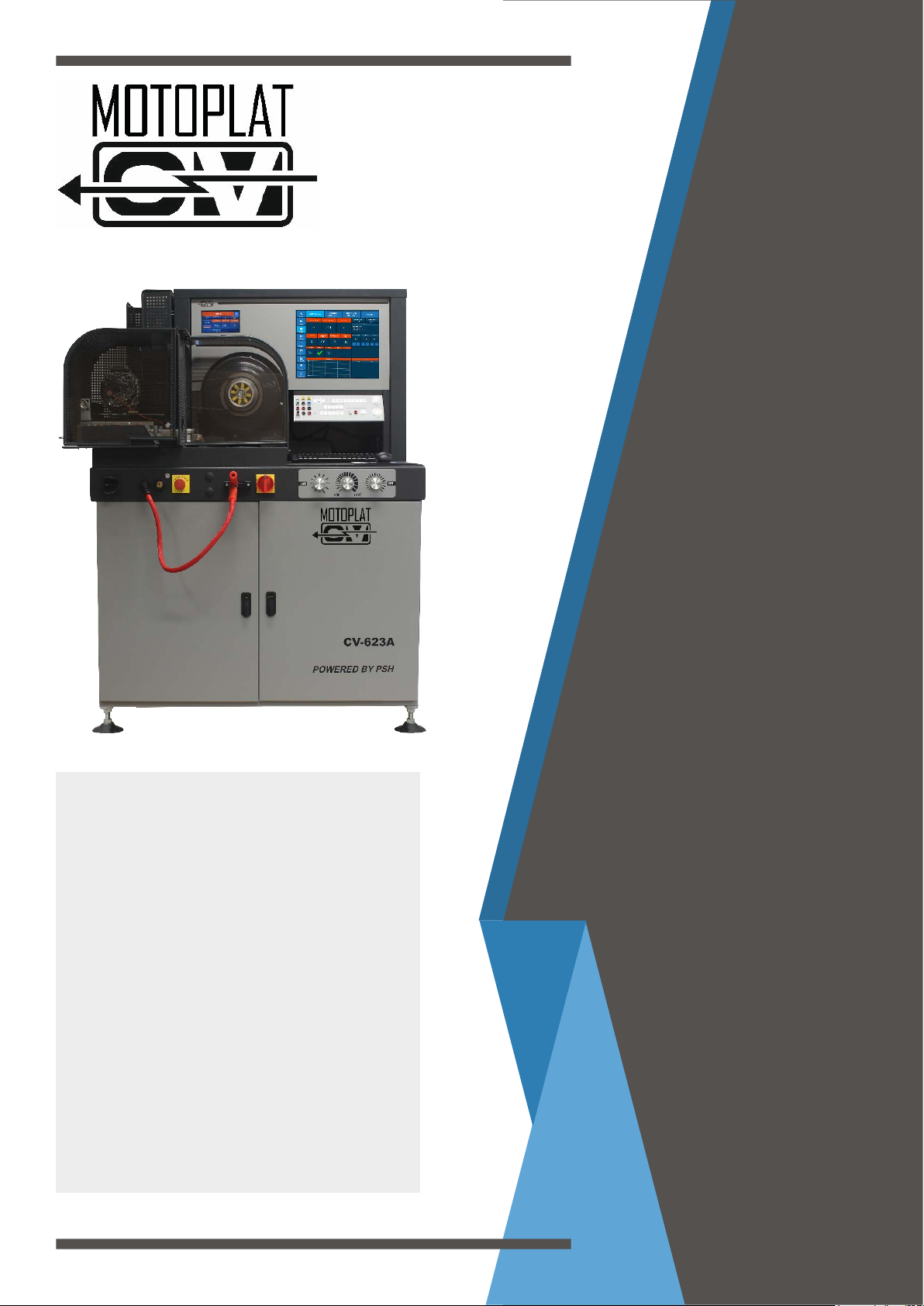
CV-623A
The CV-623A series test benches are high-end for Lab and
production use with a sturdy look and meant to last in the
modern workshop. Its high power motor in combination with its
computer controlled load bank and Siemens PLC’s makes it easy
to test up to 600amps and guaranteeing high reliability.
The CV-623A is equipped with the latest testing technology
for the modern workshop or production facility, such as API+
technology which automatically identies COM protocols
within 2 seconds. The protocols are displayed together with
their ID codes and in-depth communication data, which makes
development in remanufacturing easier, cheaper and more clear.
A modern windows PC is included for internet support and to
generate modern and extensive reports.
Test Bench
ENGLISH
VERSION 2020

Motoplat ®
Page 2
IMPORTANT INFORMATION
Safety warning
Electrical devices should be installed and operated in such a way that all applicable safety requirements
are met. It is your responsibility as an installer to ensure that you idenfy the relevant safety standards and
comply with them. Failure to do so may result in damage to equipment and personal injury. In parcular,
you should study the contents of this guide carefully before installing or operang the equipment.
Only qualied people should work with this equipment!
Prior to using this product, you should carefully review this instrucon manual or undergo training from a
qualied person.
The use of electrical equipment is enrely at your own risk and Motoplat is in no circumstances responsi-
ble for any incidental, consequenal or special damages of any kind whatsoever, including but not limited
to lost prots arising from or in any way connected with the use of the automated test equipment or this
manual.
The tester should be connected to a properly grounded outlet.
If the power cable is damaged, it must be replaced by the supplier or by another qualied person in order
to avoid dangerous situaons.
In the event that the tester comes without baeries (non-EU countries) or if you have to replace the bat-
teries, please ensure that you use approved baeries (preferably deep cycle AGM) only, as non-approved
baeries may have an adverse eect during tesng or may even damage the tester.
- Motoplat® -
Environment
The tester should be installed in a weather-protected area where heat, humidity or any other climate situa-
on will not damage the tester.
The tester should be installed on a level surface that is clear of debris and obstrucons.
It is recommended that the box and packing materials be kept for possible re-use, should the tester be
shipped again at a later me.

Motoplat ®
Page 3
Index
1 General Informaon
1.0 General informaon about the Motoplat CV-623A alternator test bench 5
1.1 Front view 6
1.2 Back view 7
1.3 Main specicaons 7
3 Alternator mounng
3.0 Intro 13
3.1 Side mounng 14
3.2 Connecng the alternator 15
2 Panels
2.0 Connecon panel descripon 9
2.1 Instrumental panel descripon 10
2.2 Instrumental panel (manual) descripon 11
Support
Contact Informaon
4 Soware
4.0 PC soware 17
4.1 Detailed informaon 19
4.2 Informaon LIN/BSS 21
4.3 Menu 22
4.4 Add alternator / alternator list 23
Technical Informaon
Technical informaon

Motoplat ®
Page 4
Section 1
General
Information
www.motoplat.nl

Motoplat ®
Page 5
General informaon about the Motoplat CV-623A alternator test bench:
The Motoplat CV-623A test bench has a 380V 3-phase power supply and can test both 12 and 24 volt
alternators. (48V ready).
To test modern alternators that have a high output at low RPM, the CV-623A is equipped with a modern
high power 22 kW(30Hp) motor and motor drive, which makes less noise than most other test benches on
the market.
The tester is equipped with the new API+ technology which automacally detects the LIN and BSS protocol
more quickly. The LIN and BSS signals will be displayed in dierent protocols together with the ID code,
which makes development in remanufacturing easier, cheaper and clearer.
The CV-623A also tests RVC, PWM, C, DFM, externally regulated and PD-controlled alternators.
An in-depth DFM tester is also built in, which displays the oset frequency of a DFM signal.
The test bench is CE marked for use in any workshop or workplace that demands safe and reliable
equipment.
Requirements installaon area:
The tester must be placed on a at and stable surface.
The oor must be solid enough to easily bear the weight of the tester!
Weight: 800 kg
Please leave an extra square meter at the front and sides free to ensure a good and safe working
environment.
Power supply
Connect the alternator tester to a 400 V three phase voltage supply. Each phase must be protected by a 32
A fuse.
Behind the front doors there is enough space to mount two 12 V baeries AGM with a capacity range of 40
to 100 ampere-hours (Ah) each. It is recommended that AGM baeries are used. They are designed to work
with Start-Stop systems, as they are more resistant to voltage uctuaons and there is no risk they will dry
out!
CAUTION!
The posive (+) and negave (-) poles must not be confused with each other. Otherwise, the alternator
tester can be damaged. The poles are well marked on the baeries as well as on the wires. When the
voltage is 24 V, the baeries are connected in series. Therefore, the baeries should be of the same brand,
type and condion (age and usage level). It is preferable to use baeries with a capacity of 70 Ah. During
every alternator test, the baeries are being charged and they should not become discharged. Nevertheless,
the baery charge level should be checked periodically. If the need arises, the baeries should be charged
by means of a recer. If the baeries are damaged, they must be replaced with new ones. Discharged
or damaged baeries can have a signicant inuence on the test and test results. Connect compressed
air supply on the back of the alternator tester. The compressed air of 8-10 bar is crucial for the pneumac
system controlling the tensioning of the drive belt. When the compressed air pressure is 8-10 bar, the drive
belt tension is about 1000 N.
Secon 1 – General informaon

Motoplat ®
Page 6
1Two-way pneumac belt tension valve 8Instrumental panel (manuel use)
2Power lead (+) 9Alternator mounng panel
3Addional socket (+) 10 Connecon panel
4Emergency stop switch 11 Instrumental panel
5Plaorm control up/down when the alternator is
mounted on the front
12 Secondary screen
6Insulated support (+) 13 Main screen
7Main switch
123 4 5 67
9
10
1.1 Front view:
Figure 1.
8
11
12 13

Motoplat ®
Page 7
2Compressed air connecon
3Data plate
1.2 Back view:
1.3 Main Specicaons:
Measurements
Width 120 cm
Depth 88 cm
Height 150 cm
Weight ca. 800 kg
(depending on the weight of the baeries)
Electric equipment
Motor Three-phase, supply voltage 600V, power 22kW/55A
Motor
RPM
“Le/right” switching, stepless speed control in the
range of 0-6000 RPM.
Inverter Winner V-60 15 kW/18.5 kW
Resistors 10 units with total current capacity of 600 A, step-
bystep load adjustment, including one with stepless
adjustment from 0-80 A.
Tester-alternator communicaon
A. Load indicator lamp 12 V/24 V (convenonal)
B. Digital (based on three types of BSS signals and 35
types of LIN signals used in cars from 2000 to 2018).
In the event of the introducon of new computer
alternator communicaon systems, the updates
with the latest command signals database will be
available.
C. Using informaon from the alternator about the
actual value of the rotor current (DFM+ and DFM-) –
aer pressing the DFM key, detailed frequency and
oset data on the COM display will appear.
D. Using C for Hyundai, Mitsubishi and Nissan and C1
signals characterisc for Honda.
Security and key safety informaon
This product fully complies with
actual CE requirements.
Safety and protecon elements MUST
NOT BE MODIFIED!
Main circuit breaker switch
Emergency stop switch
Safety cover lock protecon switch
Electric circuit wires
Metal safety cover
Figure 3.
Figure 2.

Motoplat ®
Page 8
Section 2
Panels
www.motoplat.nl

Motoplat ®
Page 9
COM Computer communicaon (API+) LIN or BSS
DFM- / DFM+ Informaon from the alternator about the present value of the rotor current in percentage depending on
the type of current control (current is transferred to the posive polarity brush (DFM+) or negave polari-
ty brush (DFM-)).
C
RLO
SIG
PWM control system used on Nissan, Hyundai and Mitsubishi applicaons.
Toyota “Sense” PWM control system.
PWM computer control signal used on Ford, Land Rover and Asian applicaons.
WFrequency- frequency [Hz] of W terminal or tacho
DRIVE Mazda alternator voltage control terminal.
PHASE/DRIVE (PD) Mazda control system (PHASE – output of the alternator phase).
B+ Posive connecon (connuous supply).
15 IGN, ignion or switched B+
GND Ground connecon.
LAMP Lamp connecon (convenonal terminal).
Fuse Automac 5A fuse used for protecon of connecon panel
F1/F2 External regulator connecon. The testbench is equipped with external regulator for alternators that
require this. Simply connect f1 and f2 terminals for alternator.(Chrysler)
Alternator test „Automac” pre-connected harness connecon(set included)
Only rev generator Reversible alternator harness connecon(Start/Stop units)
Regulator test Regulator test harness connecon. Connect regulator-less alternator for tesng the regulator (Set only
included with the CV-623A)
Scope Oscilloscope probe connecon(started from the soware for addional tesng)
2.0 Connecon panel descripon:
Motoplat ®
Page 10
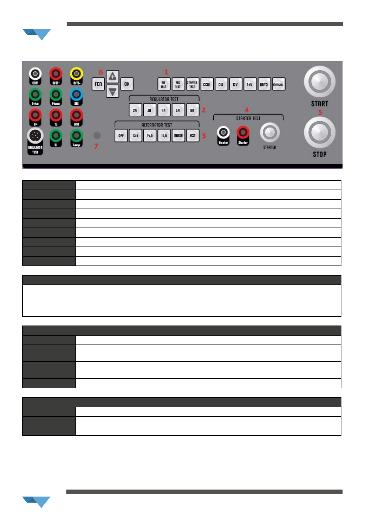
2.1 Instrumental panel descripon:
ALT TEST alternator tesng mode
REG TEST regulator tesng mode
STARTER TEST starter tesng mode
CCW couter clockwise rotaon
CW clockwise rotaon
12V 12 volt seng
24V 24 volt seng
AUTO automac tesng mode
MANUAL manual tesng mod
2. Regulator Test (acve only if reg test is on)
4A/5A/6A/7A/8A- rotor resistance seng. To test a regulator, depending on rotor resistance. This will simulate the rotor
load or alternator load. It can be checked with mulmeter or on an alternator where you want to test the regulator. Set the
resistance (4A,5A,6A,7A,8A) that you get from the mulmeter (Alternator without regualtor is included only with the CV-623A
with harness set)
3. Alternator Test( acve only if alt test is on)
OFF turns alternator voltage o( for LIN and BSS only)
12,5/13,5/15,5 set voltage setpoint for and alternator, works only if pressed, if not the voltage setpoint is by default 14,5
( for LIN and BSS only)
MODE scroll through the control modes, select mode- Search(LIN and BSS), DFM, LAMP, PWM FORD LAND
ROVER, PWM SCANIA, PWM GM, C HYUNDAI/KIA, C HONDA, C NISSAN, PD MAZDA, RLO TOYOTA, B+B-
RST resets the regulator control computer and goes back to search( LIN and BSS only)
4. Starter test( acve only if starter test is on, or IST(start/stop) type alternator is connected)
Vmeter connect wire to the starter eld, between motor and selenoid to measure voltage drop
STARTER connect to solenoid 15(switch connecon)
STARTER BUTTON starts the starter test, works for 3 sec. only.
Motoplat ®
Page 11
5 START and STOP buons
START start the test in both automac and manual mode. Note that when „start” is pressed, the general seng
buons are locked, unll „stop” is pressed.
STOP stop the test in both automac and manual mode
6. FCN/+/-/OK
NOT IN USE (for future use and upgrades)
7. Charging lamp
If lamp alternator is connected, it should be on, when alternator is charging it should be o
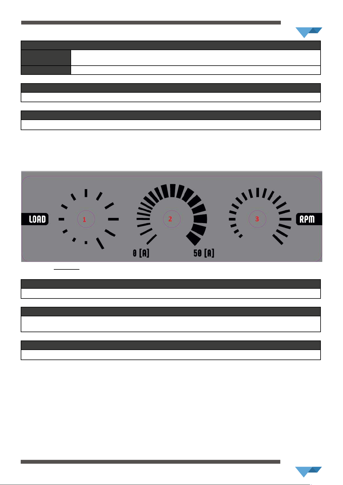
2.2 Instrumental panel (manual) descripon:
IN USE FOR MANUAL MODE ONLY
1. LOAD
Set alternator load in 12 steps of 50amps each(from 0A to 600A)
2. 0A-50A
Stepless regulaon of Load between 0A and 50A
Only funcons when the „LOAD” knob is in the rst or any other poson except the rst.
3. RPM
Stepless „revoluon per minute” regulaon (only to be used in „Manual Mode”)

Motoplat ®
Page 12
Section 3
Alternator
Mounting
www.motoplat.nl

Motoplat ®
Page 13
Secon 3 – Alternator – mounng
3.0 Intro:
Depending on the construcon of the alternator, it can be mounted on the alternator tester in such a way
that it can be powered directly by the motor (direct drive) by means of proper connecng elements or
belt (side mounng). All the parts needed to mount the alternator are included in the tooling equipment
accompanying the alternator tester. Aer mounng the alternator, connect it to the electric circuit of the
alternator tester. This diers per alternator: please refer to our webshop www.psh.nl or other.
Motoplat ®
Page 14
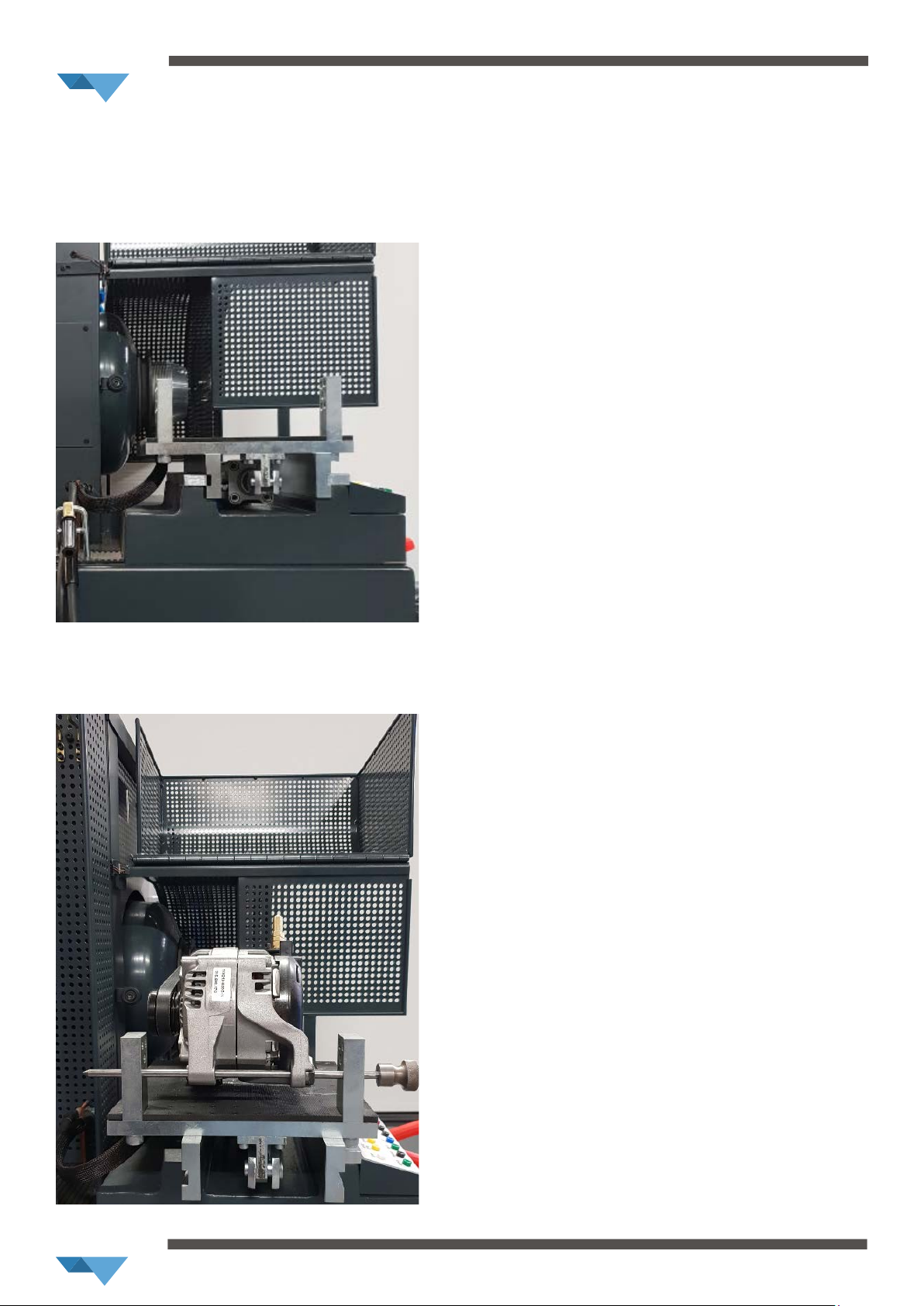
4.1 Side mounng
In order to mount the alternator on the side of the alternator tester, use a plaorm that is placed on the
le side of the alternator tester. In the case of alternators with a pad mounng soluon, rst aach a
support that is placed on the side of the alternator tester with spindles that have the correct diameter. The
spindles are also placed on the side of the alternator tester (Photo below).
Next, mount the alternator by pung appropriate spindles into the holes that are placed on both sides of
the support (Photo below).

Motoplat ®
Page 15
To mount alternators that are longitudinally mounted, use only spindles (with the correct diameter)
without the support (Photo below).
3.2 Connecng the alternator
Aer mounng the alternator, connect it to the electric circuit of the alternator tester. Connect the power
lead to the posive terminal of the alternator B+ (2, Figure 1). Then, depending upon whether it is a
computer-controlled alternator or a convenonal one, use the correct connectors and buons on the
connect and control panel (21, Figure 1).

Motoplat ®
Page 16
Section 4
Software
www.motoplat.nl

Motoplat ®
Page 17
1. Main screen
Main screen of the soware. We have 3 dierent main screens for 3 dierent tests( alternator test, starter test, regulator test).
Chosen test procedure(alternator/starter/regulator) is shown on the orange eld below the „main screen” buon. Shows
basic informaon of ( alternator/starter/regulator).
2. Detailed informaon
Go to detailed informaon. Contains all the parameters of alternator in real me during the test.
3. Informaon LIN-BSS
Detailed informaon about LIN and BSS type alternator, connecon denion.
4. Results
Results table that is lled during and aer the test. Possibility to print or save report as pdf.
5. Start
Start the test procedure.
4.0 PC Soware

Motoplat ®
Page 18
6. Stop
Stops the test procedure.
7. Add alternator
Wizard to add alternator to the database. Simply connect desired alternator and follow the instrucons step by step on the
screen. Aer the test is done it will be added to test-bench database for further comparison test.
8. Alternator list
Alternator database. It contains all the alternators that are saved in database for comparison tesng.
9. Select model
Select regulator control method see “instrumental panel” paragraph above “Modes”.
10. Comparave test
Quick test to compare 2 alternators without adding it to database.
11. Test sengs
Choose test procedure: slow (Endurance test), standard (default), fast (Producon) and „user” test. User test- test parameters
can be custom dened by the user.
12. Oscilloscope
Start oscilloscope soware (picosope built-in).
13. Selecon
Field showing test sengs and part number of an alternator from database (if chosen).
14. Diameter
Set the actual alternator pulley diameter
15. Voltage
Load voltage set-point seng. (Default seng is 13,5) Can be edited.
16. Delay
Set me delay for alternator with so-start.
17. Text eld
Shows current test informaon, pass/fail.

Motoplat ®
Page 19
4.1 Detailed informaon
This screen shows detailed informaon about the tested alternator and test bench
System alternator system
Voltage regulator manufacturer of voltage regulator (com alternator only)
Com code code of the LIN/BSS regulator
Transmission speed com regulator speed (Bauderate 9600 or 19200Kb)
Cycle me test procedure duraon
Com rpm Start/stop alternators send rpm informaon in com transmission
Electrical error electrical error send by regulator
Mechanical error mechanical error reported by regulator
Temperature error thermal error reported by regulator
Scania test yes/no 24V PWM alternator test for RVC/PWM controlled 24V units
Voltage/duty refers to Scania test shows voltage/duty cycle in 24V PWM test
Requested voltage shows requested voltage demanded from the test bench
Voltage set point shows voltage set-point of regulator
C regulaon „C” alternator funcon
Quiescent voltage Inial baery voltage of the test bench before the test starts

Motoplat ®
Page 20
This screen shows detailed informaon about the tested alternator and test bench
Ripple shows the ripple of alternator in Amps
Eciency eciency of alternator shown in %
Torque max torque in Nm used during the test
Motor power Power[kW] of motor used during the test
Operaon mode „auto” or „manual”
Selected voltage show if 12V or 24V is selected
Direcon direcon rotaon of the motor CW or CCW
Auto report print on/o if on the report will be printed automacally aer every test
Serial number Siemens PLC soware serial number
Version Siemens PLC so version
System version Siemens PLC system version
VC-07 version “07” upgrade version
VC07 keyboard instrumental panel soware version
Counter number of tests ran by the test bench
Table of contents
Other PSH Test Equipment manuals


Popular Test Equipment manuals by other brands


Sense-Ware
Sense-Ware T-229/4P USER GUIDE AND INSTRUCTIONS

Lovibond
Lovibond Tintometer TB 350 quick start guide

MONARCH INSTRUMENT
MONARCH INSTRUMENT Nova-Pro 300 instruction manual

National Instruments
National Instruments SMB-2145 user guide

Tool it
Tool it PBT 550 Translation of the original instructions

Sealey
Sealey TA301 instructions