PSI Audio AVAA C214 User manual
User Manual
AVAA C214
6.2023

PSI Audio AVAA C214 User Manual / 6.2023 Page Nr 2 PSI Audio AVAA C214 User Manual / 6.2023 Page Nr 3
AVAA C214 AVAA C214
1 Introduction ............................................................................................................................................ 3
2 Safety Instruction ................................................................................................................................... 3
2.1 Warnings............................................................................................................................................ 4
2.2 Service............................................................................................................................................... 5
3 General Overview ................................................................................................................................... 6
3.1 Description......................................................................................................................................... 6
3.2 Before you start ................................................................................................................................. 7
3.3 Front Panel Description ..................................................................................................................... 7
3.4 Rear Panel Description...................................................................................................................... 8
Power On / Off Switch ................................................................................................................................ 8
Setting buttons (blue an red) ...................................................................................................................... 8
4 Quick Start .............................................................................................................................................. 9
Quickstart Guide .................................................................................................................................... 10
5 Operation .............................................................................................................................................. 11
5.1 Standalone mode -Power ON LED (Green)....................................................................................11
5.2 Remote mode -Power ON LED (Blue) ............................................................................................11
5.3 Limiter...............................................................................................................................................11
5.4 Standby / Overheat (Red).................................................................................................................11
5.5 Controlling gain of your AVAA C214 .................................................................................................11
6 Remote mode (wireless network) ....................................................................................................... 12
6.1 Remote Control ............................................................................................................................... 12
6.2 Enable/Disable wireless network ..................................................................................................... 13
6.3 Factory reset.................................................................................................................................... 14
6.4 Reset the wireless network credentials ........................................................................................... 14
6.5 Firmware update.............................................................................................................................. 15
7 Placement and positioning in room ................................................................................................... 16
7.1 Environment .................................................................................................................................... 16
7.2 Positioning ....................................................................................................................................... 16
7.3 Mounting with optional feet.............................................................................................................. 17
8 Troubleshooting ................................................................................................................................... 18
8.1 Power on LED does not light up. ..................................................................................................... 18
8.2 AVAA C214 is unstable and emits noise.......................................................................................... 18
8.3 Connection problem with the remote control ................................................................................... 18
9 Certicates of conformities................................................................................................................. 19
9.1 C.E. & RoHS Conformities .............................................................................................................. 19
9.2 Compliance to FCC Rules. .............................................................................................................. 19
10 Warranty ................................................................................................................................................ 20
TABLE OF CONTENTS 1 Introduction
Thank you very much, and congratulations on your decision to purchase our digital active bass trap,
the AVAA C214.
You can use it in 2 different modes: Standalone Mode or Remote Mode.
-Standalone Mode (not connected to a wireless network): when you unpack your AVAA C214 and
turn it on for the rst time,it will work like the AVAA C20, you can manually turn it on and off. The
LED is green when it is working.
-Remote Mode (connected to a wireless network): thanks to digital technology, you can now
control your AVAA C214 using an app. When you are in this mode, the LED is blue.
In this user manual, we will always refer to “Standalone Mode” and “Remote Mode”.
Carefully following the instructions in this manual will ensure that your system will give you many
years of reliable and trouble free operations.
For the latest information, help or advice, please contact your local PSI Audio representative or PSI
Audio directly.
Relec S.A.
Rue des Petits Champs 11 a+b
CH-1400 YVERDON (Switzerland)
Tel : +41 (0)24 426 04 20
Fax : +41 (0)24 426 04 51
www.psiaudio.com
2 Safety Instruction
This symbol alerts the user to the presence of electrical
power within the product that may be of sufcient
magnitude to constitute a risk of electric shock.
This symbol alerts the user to important operating and
maintenance (servicing) instructions or warnings.
PSI Audio AVAA C214 User Manual / 6.2023 Page Nr 4 PSI Audio AVAA C214 User Manual / 6.2023 Page Nr 5
AVAA C214 AVAA C214
2.1 Warnings
• Please read and follow the instructions carefully prior to operating the AVAA C214.
• An AVAA C214 positioned above oor level represents a fall hazard. Please make sure your
device is always securely positioned or mounted in a stable position and can’t fall. In particular
make sure no child can make it fall.
• Please do not open the AVAA C214 device - risk of electric shock.
• Make sure not to expose the AVAA C214 to any form of liquid. For cleaning, use only a dry cloth.
In order to prevent spills, do not place any containers containing liquid on the AVAA. Do not use
the AVAA close to water as this may create an electric shock hazard.
• Only use three wire mains cables and connectors with earth (grounding) according to your
country standard.
• Do not operate the AVAA C214 in a conned environment:
Your AVAA has been designed to be placed on the rubber foot located under the case. We
recommend that you place it on a flat, solid and stable surface.
• The AVAA C214 is designed to work in rooms of minimum 10 m2. It is generally most effective
when positioned in a corner. Avoid positioning any large reective object less than 1 meter away
from the front of the AVAA C214 as it may cause instability.
• Do not operate or install the AVAA C214 near any kind of heat source.
• Only operate the AVAA C214 with accessories specied by PSI Audio.
2.2 Service
The AVAA C214 contains no user-serviceable parts. Service must be performed by qualied
personnel. The unit must not be opened by the user – risk of a severe electric shock.
Servicing is required when:
• the AVAA C214 has been damaged in some way, such as when the power-supply cord or plug is
damaged
• the AVAA C214 has suffered from exposure to rain or moisture
• liquid has been spilled into the AVAA C214
• objects have been dropped into the AVAA C214
• the AVAA C214 does not work correctly
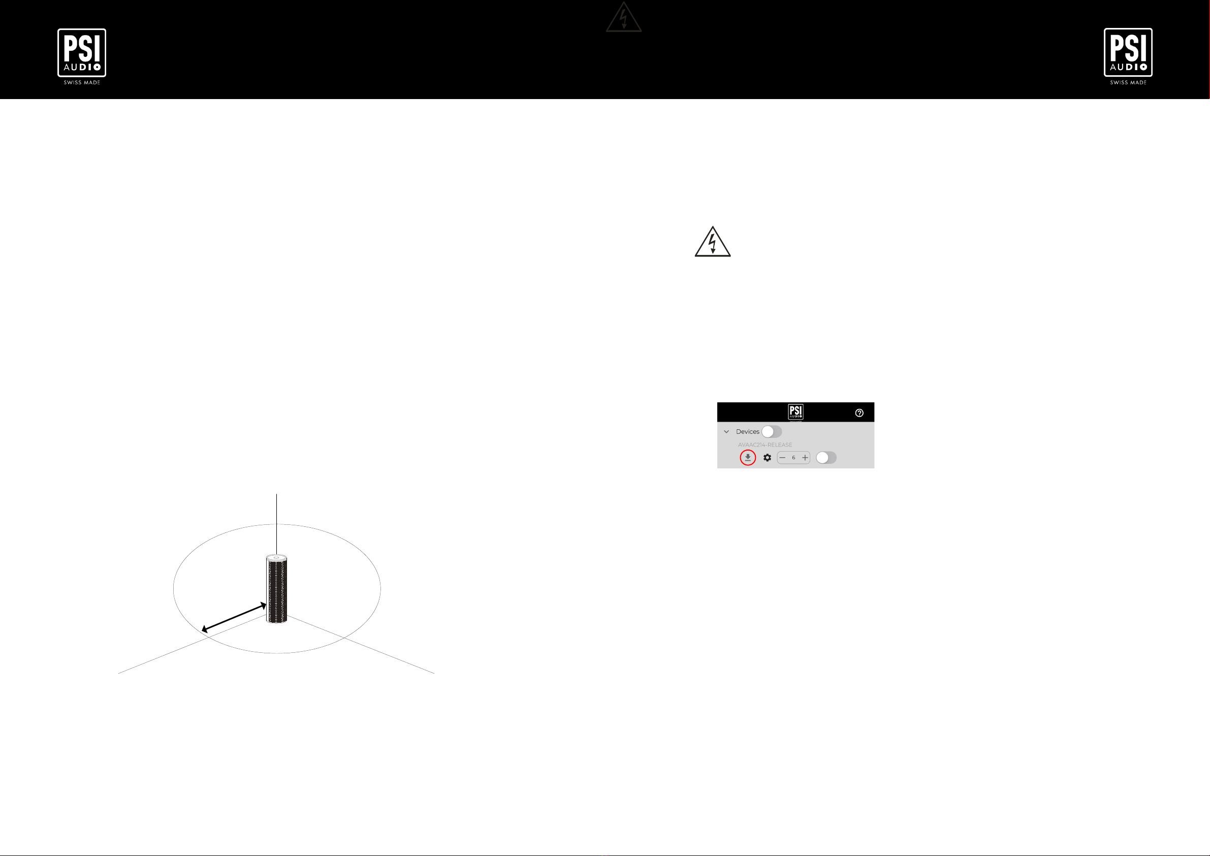
Software update:
• If software or rmware update is required, you will see it in your Smartphone app:
Spare part supply:
• for ordering, please contact your authorized reseller, mentioning your AVAA C214 model and serial
number (see point 3.4.).

PSI Audio AVAA C214 User Manual / 6.2023 Page Nr 6 PSI Audio AVAA C214 User Manual / 6.2023 Page Nr 7
AVAA C214 AVAA C214
3 General Overview
3.1 Description
The AVAA C214 is designed to absorb the standing modes between 15 and 160 Hz in a room. Above
these frequencies, passive systems are effective. For best results, the AVAA C214 should be installed
in a room where medium and high frequencies have already been treated with passive systems.
With frequencies below 160 Hz, each operating AVAA C214 will have the same effect as a hole in the
wall much larger than the dimensions of the AVAA C214.
The exact size will depend on the frequency and environment but typically ranges between 15 and 45
time the size of the AVAA C214..
The graph hereunder shows the typical equivalent absorption area of an active AVAA over the
frequency bandwidth it is designed to absorb.
Note that an AVAA C214 is approximately 0.13 m2so an equivalent sound absorbing area of 4 m2is 30
times the surface of the AVAA.
In normal operating conditions, the AVAA C214 does not emit any audible sound or anti-sound but only
absorbs low frequencies in a very effective way considering its size. Furthermore, it has no impact on
the direct sound from your speakers or other source.
3.2 Before you start
Special care has been taken in the packaging of your PSI Audio product. Before you start to install
it, please check that the following parts are included:
• AVAA C214
• Warranty certicate of calibration
• Quickstart Guide (also included in this User Manual)
3.3 Front Panel Description
---
__
Standalone mode - GREEN LED
(without wireless network)
Remote mode - BLUE LED
(Controlled by an app)
Overload
Overload
Waiting for connection
Connecting to Wi-Fi
Connected to Wi-Fi
Stability issue
Stability issue
Power failure
Power failure
Operating
~
__
For the detailed procedure on how to connect your AVAA C214 to the Wi-Fi network, please
refer to the chapter XXXXXXXX

PSI Audio AVAA C214 User Manual / 6.2023 Page Nr 8 PSI Audio AVAA C214 User Manual / 6.2023 Page Nr 9
AVAA C214 AVAA C214
3.4 Rear Panel Description
Setting buttons
- Adjust the efciency with blue (reduce) or red (increase) buttons
- Reset the wi credentials
- Enable/disable Wi-Fi connection
Power On / Off Switch
Power Cable
Model : PSI Audio AVAA C214
Serial : N° XXXXXXXX
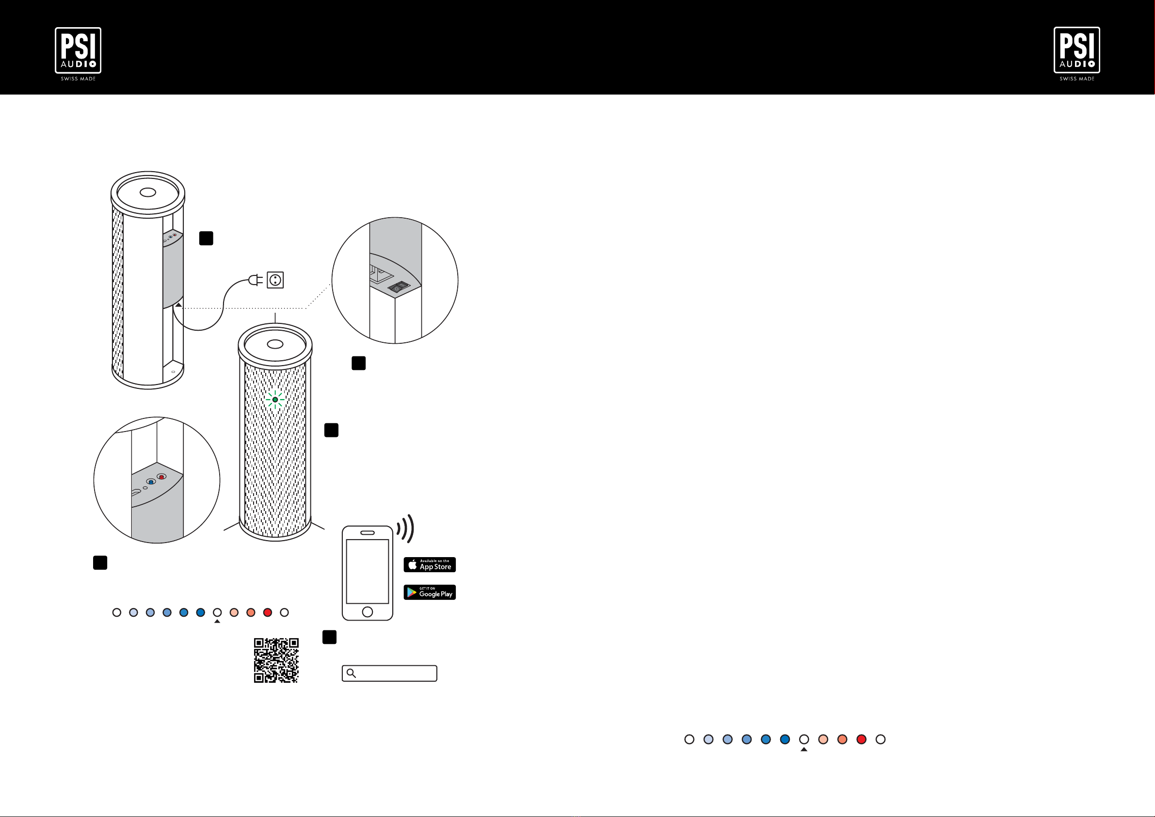
4 Quick Start
Setting up normally consists in testing the AVAA C214 in a couple of different possible locations and
using a remote control can help signicantly. However, in case you need to get started quickly, please
follow the Quickstart Guide on the next page. The rest of this manual will assist you in setting up your
AVAA C214 to your listening environment.
• Connect the power cable whilst paying attention to the warnings mentioned under the chapter safety
instructions.
• The AVAA is a large bandwidth absorber designed to be effective between 15 and 160 Hz in
environments that are already absorbing in higher frequencies such as living rooms and studios. In
theses environments no adjustment is necessary.
• We draw your attention to the fact that this AVAA C214 may, in some critical conditions, become
unstable and emit noise. PSI Audio declines all responsibility for eventual damage caused by the use
of their AVAA under unstable conditions.
• The AVAA C214 has the advantage of being able to adjust its sensitivity (gain) to the best value,
depending on the environment it is in. The sensitivity can be increased until the rst sign of instability
appears.
PSI Audio AVAA C214 User Manual / 6.2023 Page Nr 10 PSI Audio AVAA C214 User Manual / 6.2023 Page Nr 11
AVAA C214 AVAA C214
QUICKSTART GUIDE
AVAA C214
-12 -9 -6 -4.5 -3 -1.5 +0
-
CAL
+1.5 +3 +4.5 +6 dBdB
3PLACE IN CORNER
AND/OR TEST
IN DIFFERENT
LOCATIONS
2SW ITCH ON
1CONNECT TO
POW ER
4ADJUST GAIN W ITH BUTTONS
MAX ONE LEVEL BELOW FIRST
SIGNS OF INSTABILITY
5APPLICATION FOR
REMOTE CONTROL
DOW NLOAD USER MANUAL
PSI AUDIO AVAA
5 Operation
5.1 Standalone Mode - Power ON LED (Green)
The LED on the front panel shows that the AVAA C214 is operational. In the event that this LED
does not lights up, check that it is connected to the AC power outlet.
In Standalone Mode, the AVAA works normally, but without the ability of controlling it without an
application. You can also increase of decrease its effectiveness (see point 5.4).
5.2 Remote Mode - Power ON LED (Blue)
To enter the Remote Mode, please follow the steps under the point 6.2 - Enable/Disable Wi-Fi.
When your AVAA C214 is working in Remote Mode, the front LED will become blue instead of
green.
5.3 Limiter
An internal limiter monitors the pressure seen by the AVAA. If the maximal absorption is
reached, the LED will shine brighter during ~2 seconds. This is the case if the AVAA C214 is
exposed and operating with sound levels above 115 dB (where the AVAA is positioned) and
working at its full capacity. In this case the AVAA LED will shine brighter as an indication that the
AVAA can’t absorb any further. This does not represent an issue, however it is recommended to
reduce the sound level. If the LED shines bright continuously, this means that the AVAA C214 is
doing its best to absorb and AVAAs in different locations are generally more effective than
positioned in the same location.
5.4 Standby / Overheat (Red LED)
The red front LED indicates that the AVAA is in standby mode. This mode is only accessible via
the remote control application and then the absorber must be paired with a wireless network.
Other cases where the LED can turn red is an overheat.
Typical causes of overheat are lack of ventilation. Check that sufcient airow is available
behind and in front of the AVAA. Positioning the AVAA in a hot location may also cause
overheating (such as radiators, direct sunlight, etc).
5.5 Controlling gain of your AVAA
When placed in some extremely reverberant environments, it could be useful to lower the
gain of the AVAA. On the other hand, if the AVAA is placed in a very well treated room, its
gain can be increased to enhance the absorption. Using the back panel rear buttons helps
you find the best gain for your AVAA.
- Pressing the blue button will lower the gain
- Pressing the red button will increase the gain
The complete range is -12 dB to +6 dB.
At minimal/maximal gain and in between (0dB calibration state), a white led will appear to
show you these specific values, as shown in the illustration herunder:
-12 -9 -6 -4.5 -3 -1.5 +0
-
CAL
+1.5 +3 +4.5 +6 dBdB
4ADJUST GAIN W ITH BUTTONS
MAX ONE LEVEL BELOW FIRST
SIGNS OF INSTABILITY

PSI Audio AVAA C214 User Manual / 6.2023 Page Nr 12 PSI Audio AVAA C214 User Manual / 6.2023 Page Nr 13
AVAA C214 AVAA C214
6 Remote Mode (wireless network)
6.1 Remote Control
PSI Audio offers you a new experience by using a smartphone as a remote control. To take
control of your AVAA C214, please download the application on the stores (search for “PSI
Audio”).
The Smartphone app allows:
• Remote control (ON/OFF) of each AVAA C214 individually or in a group.
• Remote control the gain (efficiency) of each AVAA C214 individually.
• Link to help on the PSI Audio website.
• Upgrade the AVAA C214 firmware.
Once downloaded, please follow the steps to pair your AVAA C214 to your wireless network.
Before starting the pairing operation, please check that your AVAA(s) wireless network is
enabled. Please refer to the “Enable/disable wireless network” (section 6.2).
Use only 2.4 GHz wi network!
A 2.4 GHz Wi-Fi network operates in the 2.4 GHz frequency band, which provides several
advantages over 5 GHz Wi-Fi networks:
- Wider Range: The 2.4 GHz frequency band has a longer wavelength, which means it can
penetrate walls and other obstacles more effectively, providing a wider coverage area for the
wireless network signal.
- Better Compatibility: Older devices and some smart home devices operate in the 2.4 GHz
frequency band, so a 2.4 GHz Wi-Fi network provides better compatibility with these devices.
- Lower Interference: The 2.4 GHz frequency band is less congested than the 5 GHz
frequency band, so there's less interference from other devices that use the same band, such
as cordless phones, baby monitors, and microwave ovens.
6.2 Enable/Disable wireless network
Your AVAA C214 can be connected to your wireless network. In the factory default state of the
AVAA C214, wireless network access is disabled.
If you want to use the remote control or get the latest firmware version for your device, you
must pair the AVAA C214 to a Wi-Fi network. (For the remote control, the network does not
need to be connected to the Internet).
Enable Wi-Fi
To enable the wireless network, please follow these steps:
1. Switch off (AC power supply) your AVAA C214
2. Press on the rear BLUE button and keep it pressed
3. Switch on your AVAA C214 (AC power supply)
4. Please, wait until a blink blue LEDs (~2sec) signal to ensure your AVAA has its Wi-Fi
enable.
The front led should now breath blue.
5. You are ready to connect your AVAA(s) with your smartphone application.
Disable Wi-Fi
To disable the wireless network, please follow these steps:
1. Switch off (AC power supply) your AVAA C214
2. Press and hold the rear BLUE button on the rear of the device
3. Switch on (AC power supply) your AVAA C214
4. Wait until a blue LED flashes (~2sec) to ensure that your AVAA C214 has disabled its
wireless network.
5. Your AVAA C214 wireless antenna is OFF and front LED is green
MODE SWITCHING
PSI Audio AVAA C214 User Manual / 6.2023 Page Nr 14 PSI Audio AVAA C214 User Manual / 6.2023 Page Nr 15
AVAA C214 AVAA C214
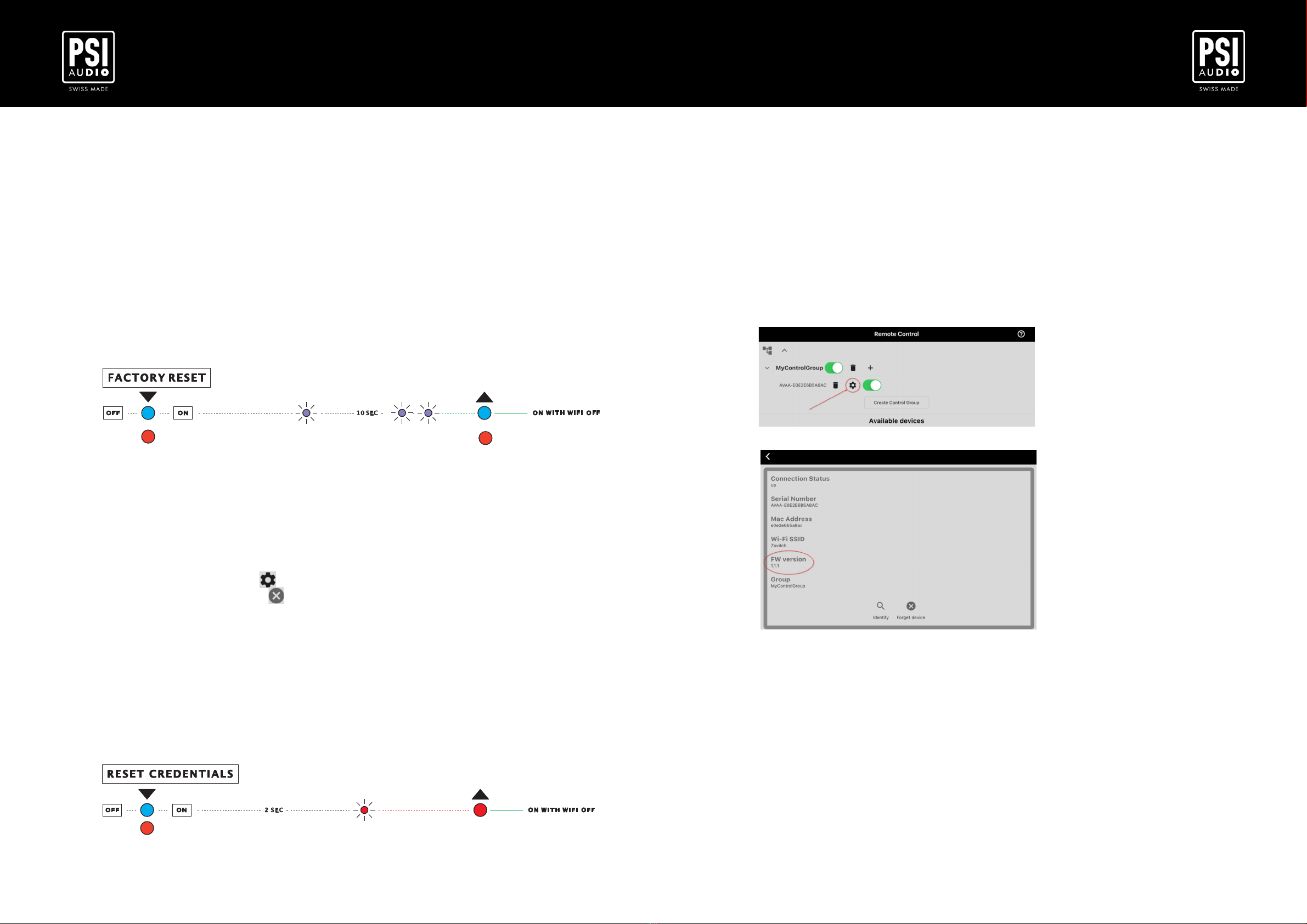
6.5 Firmware update
From time to time, we may release internal firmware updates for your AVAA C214. These are
generally minor enhancements or fixes to ensure that your C214 AVAA continues to operate
correctly.You will find the reference of the currently installed version under the settings page of
the smartphone application:
1. Ensure that your AVAA C214 is switched on and connected to your smartphone
application (please refer to remote control section)
2. Once connected to your AVAA(s) you can go under the settings button of the dedicated
AVAA C214.
3. Check the firmware version.
Using this version number, you can check at any time if a newer firmware version is available
for your AVAA model:
1. Go under the OTA update page of your smartphone application.
2. If you see the serial number of your AVAA C214 in the list, you can download a more
recent version for your device.
3. Click on the button corresponding to your AVAA C214 serial number.
4. Click on the firmware you wish to include in your AVAA C214.
5. Click on the “Update” button and wait for the procedure to finish.
6. Restart your AVAA C214 to ensure it boots with the new firmware.
You can revert to the factory firmware at any time. Please refer to the "Factory Reset" section
(6.3).
6.3 Factory reset
You can at any time reset your AVAA C214 to the factory firmware version. Either because you
find that the absorption was better before an update or because you are stuck in an unknown
behaviour.
To reset your AVAA C214, please follow these steps:
1. Switch off (AC power supply) your AVAA C214
2. Press and hold both the RED and BLUE rear buttons
3. Switch on (AC power supply) your AVAA C214
4. After a short start-up period (with the red and blue buttons still pressed), the LEDs turn
purple. Wait for the green LEDs to flash (~10 sec) to ensure that your AVAA C214 has
returned to its original state.
5. Restart your AVAA C214
6.4 Reset the wireless network credentials
It may be useful to change your AVAA C214 wireless network. Either because you have changed
your router or simply because you have travelled with your AVAA(s). There are several ways of
doing this:
The most indicated way is to use the application (Please refer to the “Remote control” section):
1. Go under the “settings” of your AVAA C214
2. Click on “Forget Device”
3. Confirm that you want to remove the device from the wireless network
If you are not able to remove the AVAA C214 from the application, you can do it manually:
1. Switch off (AC power supply) your AVAA C214
2. Press and hold the red rear button
3. Switch on (AC power supply) your AVAA C214
4. Please wait until a blink red LED (~2 sec) signal to ensure your AVAA has reset its
wireless network credentials.
5. Restart your AVAA C214
Please note that manually erasing the wireless network credentials means that the AVAA C214
left into your application is no longer controllable and you must also delete it from the application.
++
PSI Audio AVAA C214 User Manual / 6.2023 Page Nr 16 PSI Audio AVAA C214 User Manual / 6.2023 Page Nr 17
AVAA C214 AVAA C214
Positioning the AVAAs based on room measurements:
A more technical “2 steps process” can also be used to identify the best location for the AVAAs.
1 - Identify the disturbing room modes:
Assuming the loudspeakers and listening position have been set, measure the frequency decay time
in the listening position.
Note that the most disturbing room modes are the ones with the longest extinction time and not
necessarily the peaks and nulls that are the result of inevitable rst reections.
You may typically identify 3 to 6 room modes.
2 - Identify the highest pressure zones for each problematic room mode:
Play a sine wave at the frequency of each disturbing room mode.
For each of these frequencies, walk around the walls of the room and note down the highest-pressure
areas. You can do this with a sound level meter or listening with a single ear.
As a result, you should have a map of your room highlighting the wall areas most contributing to each
disturbing room mode. This will clearly show the best locations for the AVAAs.
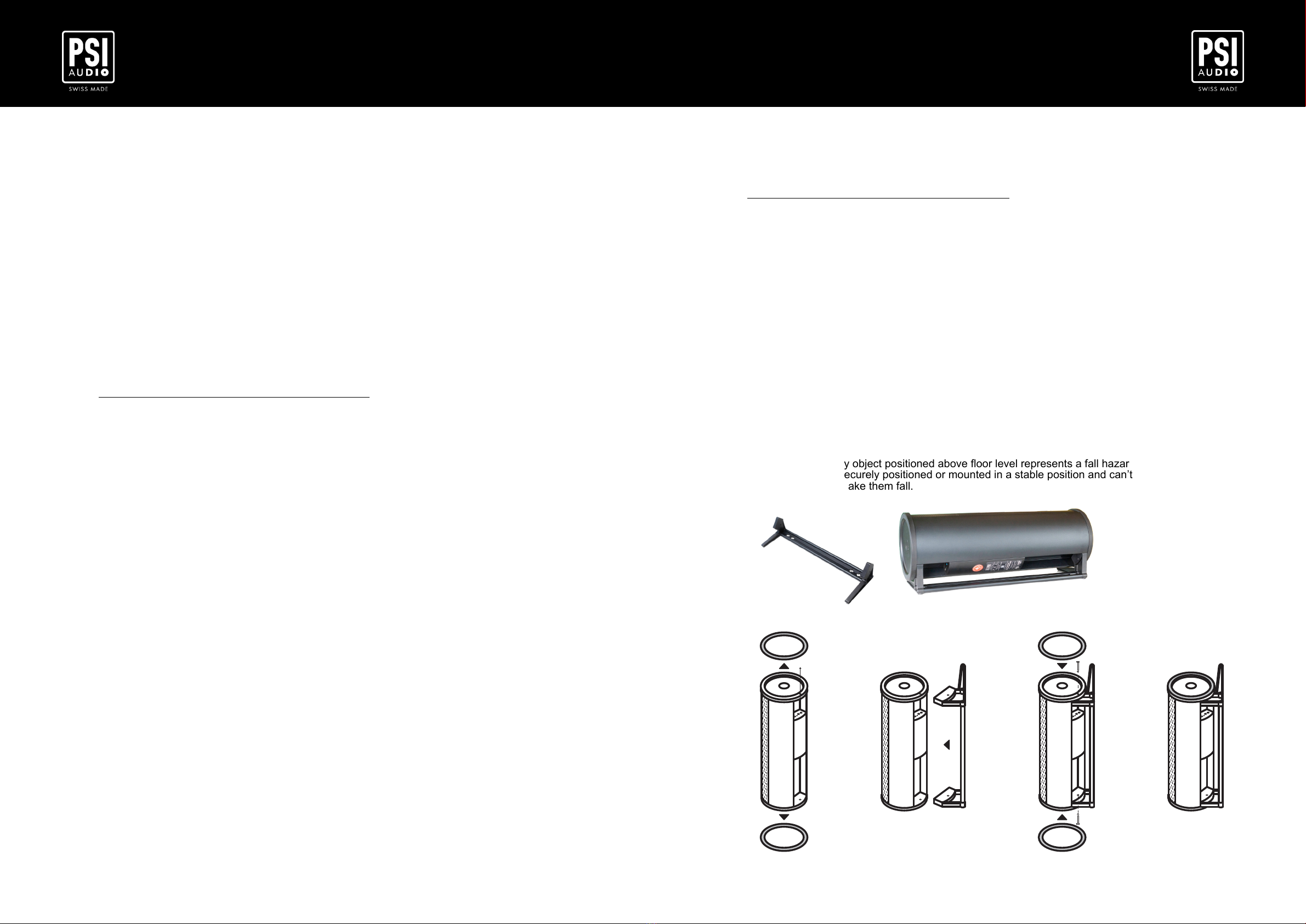
7.3 Mounting with optional feet
You can hang your AVAA C214 from the ceiling or wall using the optional mounting feet. They can
also be useful if you want to position the AVAA C214 horizontally on the oor.
Remember that any object positioned above oor level represents a fall hazard. Make sure your
AVAA are always securely positioned or mounted in a stable position and can’t fall. In particular make
sure no child can make them fall.
7 Placement and positioning in room
7.1 Environment
The AVAA C214 is designed to be effective in a living room or studio that typically have a Rt60 of less
than 2 seconds for frequencies above 200 Hz.
In small and highly reverberating rooms, you can lower the gain.
7.2 Positioning
The effect of the AVAA C214 depends on the acoustic characteristics of the room as well as the
position of the loudspeakers.
The most effective position for the AVAA C214 is in a location where the walls contribute most to the
room modes that are disturbing in the listening position. In practice it is very easy to position the
AVAA effectively after a few comparative trials.
Usual positioning of the AVAA, based on our experience
The starting position is in corners behind the source speakers as this is the most effective position in
a majority of cases. However, depending on the structure of the room boundaries and listening
position, other AVAA locations might turn out to be more effective. Try positioning them in different
corners or against walls and evaluate effectiveness.
In practice it is quick and easy nding the best location by following the basic rules:
- AVAAs positioned in corners are more effective
-AVAAs located against rigid walls are more effective
-AVAAs positioned in corners behind the source are in general more effective than other similar
corners
Bear in mind that the AVAA C214 is designed to absorb long wavelengths, so there's not much to be
gained from positioning the AVAA with great precision

PSI Audio AVAA C214 User Manual / 6.2023 Page Nr 18 PSI Audio AVAA C214 User Manual / 6.2023 Page Nr 19
AVAA C214 AVAA C214
9 Certicates of conformities
9.1 C.E. & RoHS Conformities
PSI Audio products have been tested and calibrated according to the highest quality standards.
An individual calibration diagram is provided with each AVAA produced.
The PSI Audio products have been tested according to EU directives and amendments:
Low voltage directive (LVD), 2006/95/EC
Electromagnetic compatibility directive (EMC), 2004/108/EC
The relevant technical standards are:
EN 60065: 1998 Audio, video and similar apparatus – Safety requirements (Class 1)
EN 55103-1/E1: 1996 Product Standard – Emission
Audio, Video and audio-visual apparatus for professional use
EN 55103-2/E1: 1996 Product Standard – Immunity
Audio, Video and audio-visual apparatus for professional use
This product is manufactured according to the European directive 2002/95/EC
9.2 Compliance to FCC Rules
This device complies with part 15 of the FCC Rules. Operation is subject to the following two
conditions:
• This device may not cause harmful interference, and
• This device must accept any interference received, including interference that may
cause undesired operation.
NOTE:
This equipment has been tested and found to comply with the limits for a Class B digital device,
pursuant to part 15 of the FCC Rules. These limits are designed to provide reasonable
protection against harmful interference in a residential installation. This equipment generates,
uses and can radiate radio frequency energy and, if not installed and used in accordance with
the instructions, may cause harmful interference to radio communications. However, there is no
guarantee that interference will not occur in a particular installation. If this equipment does
cause harmful interference to radio or television reception, which can be determined by turning
the equipment off and on, the user is encouraged to try to correct the interference by one or
more of the following measures:
• Reorient or relocate the receiving antenna.
• Increase the separation between the equipment and receiver.
• Connect the equipment into an outlet on a circuit different from that to which the
receiver is connected.
• Consult the dealer or an experienced radio/TV technician for help
Test report: 1472/2022
8 Troubleshooting
8.1 Power on LED does not light up
Please check that the power switch is set on the ON position and that the mains cable is properly
connected to the mains. If the problem persists, check the fuse, the voltage selector and the AC
power voltage. If this doesn’t solve the problem, please contact PSI Audio or a PSI Audio authorised
dealer.
8.2 AVAA C214 is unstable and emits noise
In normal operating mode the AVAA C214 doesn’t emit any audible sound. The presence of
reverberating objects in the near eld of the AVAA may destabilise the system and produce noise or
whistling. If the AVAA C214 becomes unstable you will distinctly hear it until the overload protection
is reached, the system stops briey and starts again.
-Remove any large reective object that is close to the AVAA C214.
-Try positioning the AVAA C214 in a different location.
8.3 Connection problem with the remote control
It might be possible that your smartphone does not find the AVAA C214 that you would like to
pair with. In this case, please check that your internet router/box has not an automatic
configuration of the frequency range of the wireless network.
To pair your AVAA, it is mandatory to have a 2.4 GHz frequency for the wireless network.
Sometimes the router prefer 5 GHz which is not compatible with the AVAA antenna.
To change this on your internet router, please check the manual of your router and disable the
automatic frequency function. You can also try to generate 2 distinct network (one at 2.4 GHz
and one at 5GHz).

psiaudio.swiss
PSI Audio AVAA C214 User Manual / 6.2023 Page Nr 20 PSI Audio AVAA C214 User Manual / 6.2023 Page Nr 21
AVAA C214 AVAA C214
10 Warranty
Our products undergo several steps of quality control to ensure they leave our factory in perfect
condition. We offer a warranty against any manufacturing or material defect for a period of 5 years on all
electronics and transducers and 2 years on the aluminium boxes. Only Relec SA is able to qualify a
manufacturing or material defect and its eligibility to be covered by the warranty. Wear and tear is not
covered by the warranty.
Please contact your reseller for any query about warranty or servicing.
We kindly remind the user that unauthorised servicing can void the warranty. In order to provide a
quality service, we ask the user to always include the warranty card at each service.
If goods need to be returned to the manufacturer (Relec SA), the symptoms must be clearly mentioned.
In case of warranty, the parts and labour costs are at the charge of the manufacturer. If no defect in
workmanship is detected, the warranty is considered invalid. A quote for the repair will be sent and the
relative cost charged to the customer.
For services (covered or not by warranty), the expenses and the risks of the transports both ways
between the customer and his supplier are the responsibility and at the charge of the customer.
For any other provision, the Swiss code of obligations, Articles 197 to 210 will apply.
For any legal action, reference will apply to the Court of Yverdon-les-Bains (Switzerland) only.
Other manuals for AVAA C214
1
This manual suits for next models
1
Table of contents
Other PSI Audio Recording Equipment manuals


