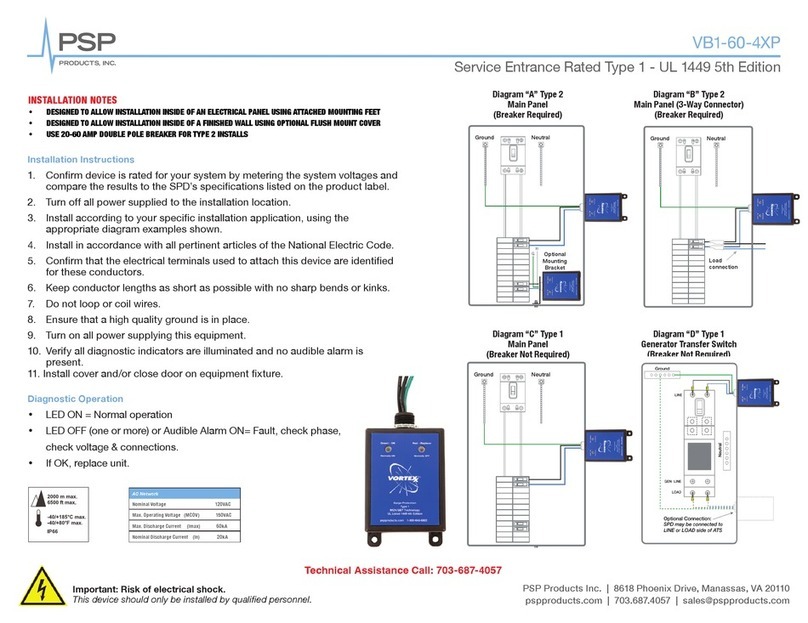
Important: Risk of electrical shock.
This device should only be installed by qualified personnel.
PSP Products Inc. | Phoenix Drive | Manassas, VA 20110
Rev: 05-24-19
PSP Products Inc. | Phoenix Drive | Manassas, VA 20110
Hurricane 4000 Series
Installation Instructions
1. Preparation for Install of
Surge Protection Device (SPD)
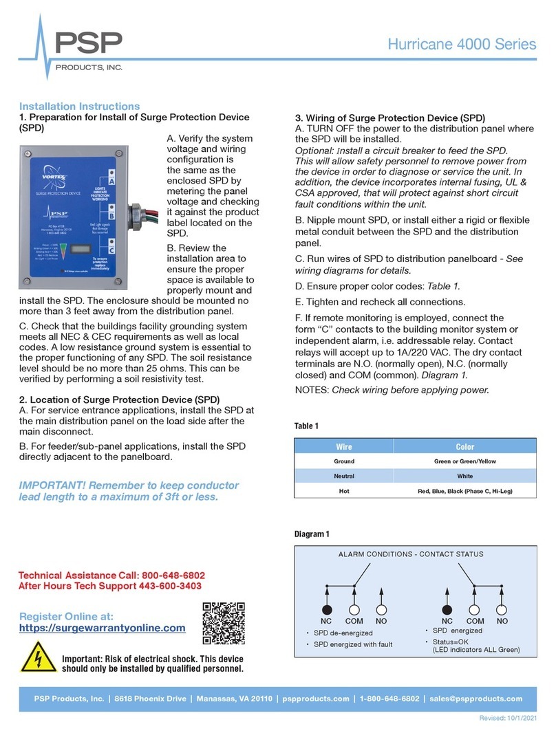
A. Verify the system voltage and wiring
confi guration is the same as the enclosed SPD by
metering the panel voltage and checking it against
the product label located on the SPD.
B. Review the installation area to ensure the proper
space is available to properly mount and install the
SPD. The enclosure should be mounted no more
than 3 feet away from the distribution panel.
C. Check that the buildings facility grounding
system meets all NEC & CEC requirements as well as local codes. A low resistance
ground system is essential to the proper functioning of any SPD. The soil resistance level
should be no more than 25 ohms. This can be verifi ed by performing a soil resistivity test.
2. Location of Surge Protection Device (SPD)
A. For service entrance applications, install the SPD at the main distribution panel on the
load side after the main disconnect.
B. For feeder/sub-panel applications, install the SPD directly adjacent to the panelboard.
IMPORTANT! Remember to keep conductor lead length to a
maximum of 3ft or less.
3. Wiring of Surge Protection Device (SPD)
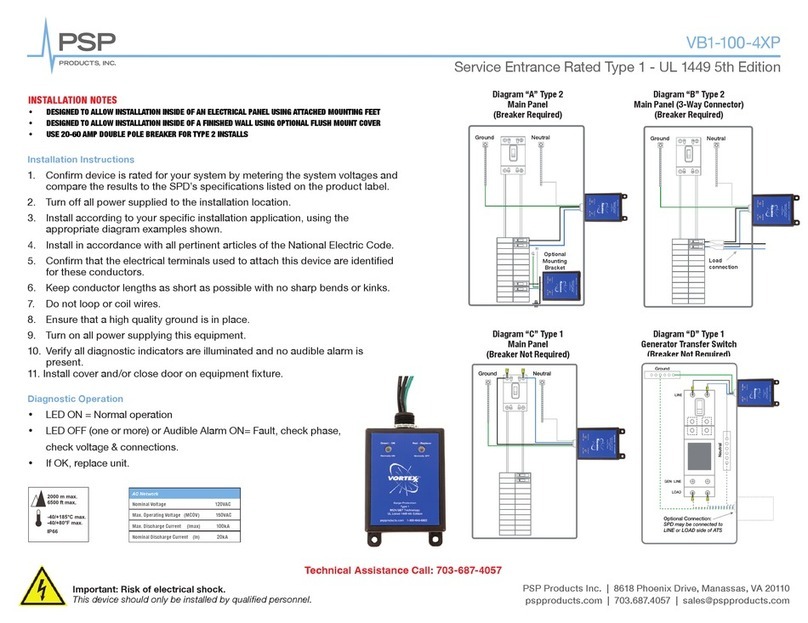
A. TURN OFF the power to the distribution panel where the SPD will be installed.
Optional: Install a circuit breaker to feed the SPD. This will allow safety personnel to
remove power from the device in order to diagnose or service the unit. In addition, the
device incorporates internal fusing, UL & CSA approved, that will protect against short
circuit fault conditions within the unit.
B. Nipple mount SPD, or install either a rigid or fl exible metal conduit between the SPD
and the distribution panel.
C. Run wires of SPD to distribution panelboard - See wiring diagrams for details.
D. Ensure proper color codes: Table 1
E. Tighten and recheck all connections.
F. If remote monitoring is employed, connect the form “C” contacts to the building
monitor system or independent alarm, i.e. addressable relay. Contact relays will accept
up to 1A/220 VAC. The dry contact terminals are N.O. (normally open), N.C. (normally
closed) and COM (common). Diagram 1
NOTES: Check wiring before applying power
Wire Color
Ground Green or Green/Yellow
Neutral White
Hot Red, Blue, Black (Phase C, Hi-Leg)
Table 1
Diagram 1
•SPD de-energized
•SPD energized with fault
•SPD energized
•Status=OK
(LED indicators ALL Green)
Alarm Conditions - Contact Status
NC COM NO NC COM NO

