PSR PAT DS350 User manual


TABLE OF CONTENTS
NOTICE
1
GENERAL INFORMATION...................................................................................... 1
2
WARNINGS ........................................................................................................... 2
3
SYSTEM DESCRIPTION.........................................................................................3
SYSTEM FUNCTION..............................................................................................................................4
OPERATING CONSOLE..........................................................................................................................4
CONTROL IDENTIFICATION...................................................................................................................5
4
CONFIGURATION SETUP.................................................................................... 10
PILE DRIVING APPLICATION ..............................................................................................................10
LMI SETUP PROCEDURE ...................................................................................................................10
HOIST-IN-USE QUICK SELECTION.......................................................................................................16
CRAWLER POSITION QUICK SELECTION (IF APPLICABLE)...................................................... 17
5
OPERATION.........................................................................................................18
LIMIT SETTING.................................................................................................................................. 20
Radius Limitation..................................................................................................21
Tip Height Limitation............................................................................................23
Boom Angle Limitation......................................................................................... 25
INFO CRANE CONFIGURATION.......................................................................................................... 27
DISPLAY CONTRAST CONTROL......................................................................................................... 28
6
PRE-OPERATION INSPECTION AND CALIBRATION VERIFICATION ....................29
7
SERVICE AND MAINTENANCE................................................................................... 33
8
TROUBLESHOOTING...........................................................................................34
9
CALIBRATION..............................................................................................................36
GENERAL INFORMATION ....................................................................................................................36
What must be calibrated?...............................................................................................36
Material required for calibration:.....................................................................................36
Calibration memory........................................................................................................36
CALIBRATION CONFIGURATION SETUP ....................................................................37
CALIBRATION ZERO SETTINGS..................................................................................37
Force Sensor Adjustment ....................................................................................38
Angle Sensor Adjustment .....................................................................................39
CALIBRATION MODE ..................................................................................................40
Main Boom Calibration......................................................................................... 41
Jib Calibration......................................................................................................43
Main Boom and Jib Calibration............................................................................. 45


Operation, Calibration & Service Manual
LinkBelt - DS350 1334 Console
1 GENERAL INFORMATION
The PAT Load Moment Indicator1(LMI) DS350 has been designed to provide the crane operator with
the essential information required to operate the machine within its design parameters.
DS350 LMI basically consists of a central microprocessor unit, graphic operator’s console, angle
sensor, force transducer sensor, and anti-two block switches. The system operates on the principle of
reference/real comparison. The real value, resulting from the load measurement is compared with the
reference data, stored in the central processor memory and evaluated in the microprocessor. If non
permitted conditions are approached, the DS350 LMI will warn the operator by sounding an audible
alarm, lighting a warning light and locking out those functions that may aggravate or worsen the
crane’s condition.
The fixed data regarding the crane, such as capacity charts, boom weights, centers of gravity and
dimensions are stored in memory chips in the central processor unit. This data is the reference
information used to calculate the operating conditions.
The boom angle is measured by the angle sensor, mounted at the boom base. The cable reel cable
serves as an electrical conductor for the anti two-block switches and force transducer signals.
The hoist load is measured by a force transducer mounted in the pendant, close to the boom tip.
The operator’s console uses interactive graphic illustrations to guide the operator through the
configuration setup and calibration programming, which considerably simplifies the input of operating
modes as well as the setting of geometry limit values.
The configuration setup allows the operator to define the crane current configuration, which the
computer uses to set the operating mode and define the limits for the crane configuration.
A calibration is required to define the load, radius, and boom angle for a specific crane configuration.
The calibration adjusts boom weights, deflection, and offsets in main boom and extension
configurations, which will be used to calculate the load moment to aid the operator in determining the
crane limits for the specific operating configuration. Refer to chapter 9 for further information.
NOTE: The zero setting of the force transducer requires that the pendent be disconnected, so
there are no external forces on the transducer.
1
LO
AD
MOM
EN
T:
generally
the
product
of
a
force
and
i
t
s
moment
arm;
speci
fically,
the
product
of
the
load
and
the
load-radius
.
Ue
s
d
in
the
determination of the lifting capacity of a crane

Operation, Calibration & Service Manual
LinkBelt - DS350 1334 Console
The LMI can only work correctly, if all adjustments have been properly set. For correct adjustment,
the operator has to answer thoroughly and correctly all questions asked during the setup procedure
in accordance with the real rigging state of the crane. To prevent material damage and serious or
even fatal accidents, the correct adjustment of the LMI has to be ensured before starting the crane
operation.
2 WARNINGS
The LMI is an operational aid that warns a crane operator of approaching overload conditions and
over hoist conditions that could cause damage to equipment and personnel.
The device is not, and shall not, be a substitute for good operator judgment, experience and use of
accepted safe crane operating procedures.
The responsibility for the safe crane operation shall remain with the crane operator who shall ensure
that all warnings and instructions supplied are fully understood and observed.
Prior to operating the crane, the operator must carefully and thoroughly read and understand the
information in this manual to ensure that he knows the operation and limitations of indicator and
crane.
The use of load or angle sensor bypass plugs for pile driving applications will render the system
inoperable from proper function and operation, and is not recommended. But, the option is available
to prevent momentary cutout conditions due to spiking load indications that may occur or interfere with
the pile driving application. After performing this application, the system must be returned to its normal
working condition with all sensors connected, and bypass plug removed. The pre-operation inspection
and calibration verification in SECTION 6 of this manual MUST be performed.
Proper functioning depends upon proper daily inspection and observance of the operating instructions
set forth in this manual. Refer to Section 6. Pre-Operation Inspection and Calibration Verification of
this handbook.
Operation, Calibration & Service Manual
LinkBelt - DS350 1334 Console
3 SYSTEM DESCRIPTION
The PAT Load Moment Indicator DS 350 consists of a central microprocessor unit, operating console,
angle sensor, force transducer, and anti-two block switches.
The system operates on the principle of reference/real comparison. The real value, resulting from the
load measurement is compared with the reference data, stored in the central processor memory and
evaluated in the microprocessor. When limits are reached, an overload warning signal is generated at
the operator’s console. At the same time, the crane functions, such as hoist up and boom down, will be
stopped.
The fixed data regarding the crane, such as capacity charts, boom weights, centers of gravity and
dimensions are stored in memory chips in the central processor unit. This data is the reference
information used to calculate the operating conditions.
The boom angle is measured by the angle sensor, mounted in the boom base. The cable reel cable
serves as an electrical conductor for the anti two-block switches and force transducer signals.
The hoist load is measured by a force transducer mounted in the pendant, close to the boom tip.
The interactive user guidance considerably simplifies the input of operating modes as well as the
setting of geometry limit values.
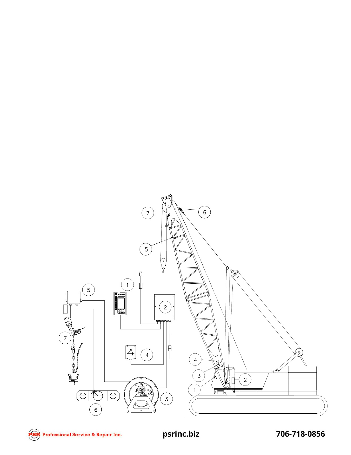
Fig. 1: Components of the LMI
System PAT DS 350
1. Operator’s Console
2. Central Unit
3. Cable Reel
4. Boom Angle Sensor
5. Junction Box
6. Force Transducer
7. A2B Switch
Operation, Calibration & Service Manual
LinkBelt - DS350 1334 Console
System Function
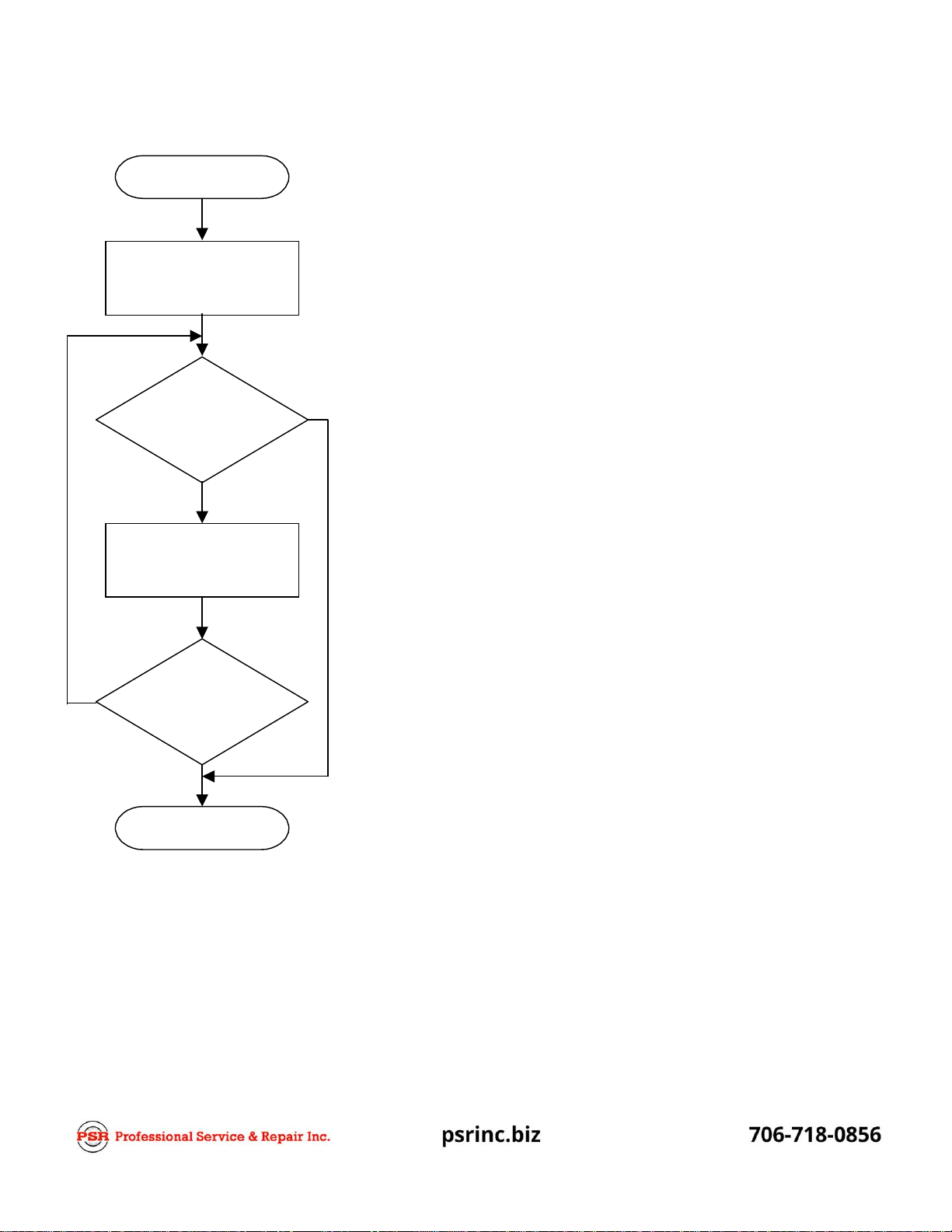
Upon switching on crane ignition switch, the system starts with
an automatic test of the LMI system, of lamps and audible
alarm. During the test, the LC display shows the initial logo.
(approximately 35 seconds)
The previous configuration setup will be displayed showing bold
symbols as selected inputs and must be confirmed OK to set the
system into operation or deleted to enter a new configuration.
(chapter4)
The operating configuration is determined by an interactive step-
by-step interrogation of the rigging states and reeving.
(chapter 4)
The configuration setup entered will be displayed showing bold
symbols as selected inputs and must be confirmed OK to set the
system into operation or deleted to enter a new configuration.
(chapter4)
The console has 3 functions:
Upon acknowledgment of the inputs the system is ready for
operation.
Operating Console
inputs by the crane operator (operating configuration, reeving, and calibration)
input of geometry limit values and signalization of exceeded limit values
display of important data and information
The operator’s console is mounted in the crane’s cab in the operator’s field of vision. For a better
identification of displays and operating elements, they are continuously backlit during operation.
START
SELF TEST
OK or DEL
operating
configuration
NO
YES
Interactive INPUT
operating configuration
NO
OK or DEL
operating
configuration
YES
OPERATIONAL
Operation, Calibration & Service Manual
LinkBelt - DS350 1334 Console
Control Identification
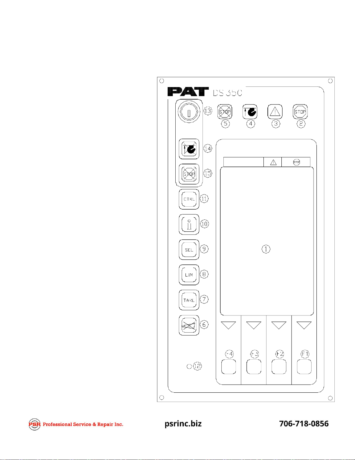
This unit contains a display and different controls that are described as follows:
Fig 2: Operator’s Console
1. LC Display Area
2. Load Moment Limit Light
3. Load Moment Prewarning Light
4. Alarm Light “Anti-Two-Block”
5. By-Pass Warning Light
6. Button “Alarm Stop”
7. Button and Control Light “TARE”
8. Button and Control Light “LIMITS”
9. Button and Control Light “SELECT
OPERATION MODE”
10. Button and Control Light "INFO"
11. Button and Control Light
"CONTROL"
12. Audible Alarm
13. By-Pass Key Switch
14. Button and Control Light "By-Pass
Anti-Two-Block"
15. Button and Control Light "By-Pass
LMI Kick-out function"
F1. Button "Function 1"
F2. Button "Function 2"
F3. Button "Function 3"
F4. Button "Function4"
Operation, Calibration & Service Manual
LinkBelt - DS350 1334 Console
1
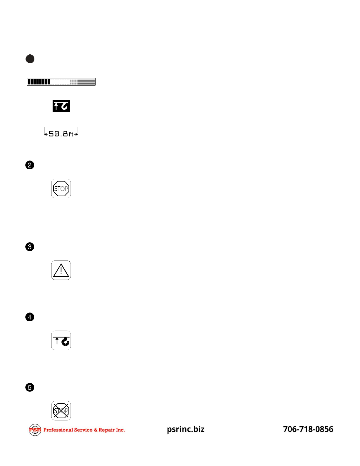
LC- Display
Examples:
Bargraph
Anti-two Block
Radius
The LC display visualizes graphical symbols, texts and numerical values.
Depending on the selected operating mode (setup, limit mode or LMI
representation), the corresponding information is indicated on the display.
Please refer to the description of the different operating modes for the
signification of the individual elements. Refer to chapter 5 for complete list
of symbols.
Load Moment Limit Light
The red LOAD MOMENT LIMIT LIGHT (2) warns the operator that a rated
load condition has been reached. It lights up when the load on the crane
reaches the crane load capacity. The audible alarm also sounds when this
condition has been reached.
The following crane movements will be stopped concurrently:
Hoist up
boom down
Load Moment Prewarning Light
The yellow LOAD MOMENT PRE-WARNING LIGHT (3) will light up when
the load on the crane reaches the defined prewarning area, thus indicating
that an overload condition is approaching.
This means for the operator to continue his crane operation with extreme
caution.
Alarm Light “Anti-2-Block”
The red “Anti Two-Block Alarm Light” (4) lights up when the anti-two-block
limit switch contacts open, indicating that a two-blocking condition is
approaching. At the same time the audible alarm will sound.
The following crane movements will be stopped subsequently: hoist up and
boom down (depending on your machine).
By-Pass Key Warning Light
The red BY-PASS WARNING LIGHT (5) flashes to indicate that the kick-
out function of the A2B / LMI system is deactivated.

Operation, Calibration & Service Manual
LinkBelt - DS350 1334 Console
Button and Control Light “Alarm Stop”
This ALARM STOP BUTTON (6) allows the audible alarm to be silenced for
approximately 15 seconds by pressing this button. Reference “Audible
Alarm” (12).
Button and Control Light “Tare”
The button “TARE” (7) is used to indicate the “Net load” on the LC Display
(1). Net load is the present load, less lifting tackle and hook block. The Tare
Button (7) has to be activated before lifting.
After pushing the “Tare Button” (7) the load display is set to zero (taring)
and the control light lights up. After lifting a load the display shows the net
load (pay load).
The net load display will change to the actual load display when the boom
radius is changed (either by angle or length).
B utton "LIMITS"
Button to start the function "program limit values".
For the proceeding please refer to chapter 5.1.
Operation, Calibration & Service Manual
LinkBelt - DS350 1334 Console
The correct setting is of utmost importance for the proper f unction of the system and the crane.
Therefore only operators who are thoroughly familiar with use and operation of the system shall set
this button.
But ton "SELECT"
Button to start the function "set operating mode".
For the proceeding please refer to chapter 4.1.
B utton "INFO"
Button to start the function "information crane configuration"
Please refer to chapter 5.2.
B utton "CONTROL"
Button to start additional functions.
Please refer to chapter 5.3.
Audible Alarm
The AUDIBLE ALARM (12), sounds during the following conditions:
overload condition
approaching two-block condition
preset limits reached
malfunction of the LMIsystem
operating error
˜T he alarm can be temporarily silenced by pushing the button “Alarm Stop”
(6).
Operation, Calibration & Service Manual
LinkBelt - DS350 1334 Console
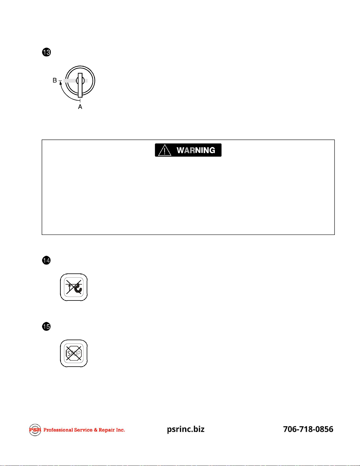
Key Switch
The ant i-two-block sw itch k ick-out f unction is deact ivated w hen the KEY
SWITCH (13) is turned to position "B" and t he “By-pass A2B” button (14) is
pushed.
Or
The LM I k ick-out f unction is deact ivated w hen t he KEY SW ITCH (13) is
turned to position "B" and the “By-pass LMI” button (15) is pushed.
KEY SWITCH (13) can be operated only by using the matching button.
Button "By-pass A2B"
This button can be operated only if key switch (13) is turned to position B.
While pushing this button, the kick-out function of the anti-two-block switch is
deactivated.
The By-Pass Warning Light (5) flashes to indicate that the kick-out function is
deactivated.
Button "By-pass LMI"
This button can be operated only if key switch (13) is turned to position B.
While pushing this button, the control lever lockout function of the LMI is
deactivated.
The By-Pass Warning Light (5) flashes to indicate that the kick-out function is
deactivated.
Since button (14) and (15) deactivate the kick-out function of the LMI system / the anti two-block
system, the following instructions must be obeyed:
The by -pass f unction shall be used w ith discr etion, as unw arranted use of it t o ov erride the
control lev er lock out sy stem can r esult in har m t o t he cr ane and dang er t o pr operty and
persons.
Never use t he by-pass f unction t o eit her overload or operate the cr ane in a non-permissible
range.
Operation, Calibration & Service Manual
LinkBelt - DS350 1334 Console
The use of load or angle sensor bypass plugs for pile driving applications will render the system
inoperable from proper function and operation, and is not recommended. But, the option is
available to prevent momentary cutout conditions due to spiking load indications that may occur or
interfere with the pile driving application. After performing this application, the system must be
returned to its normal working condition with all sensors connected, and bypass plug removed. The
pre-operation inspection and calibration verification in SECTION 6 of this manual MUST be
performed.
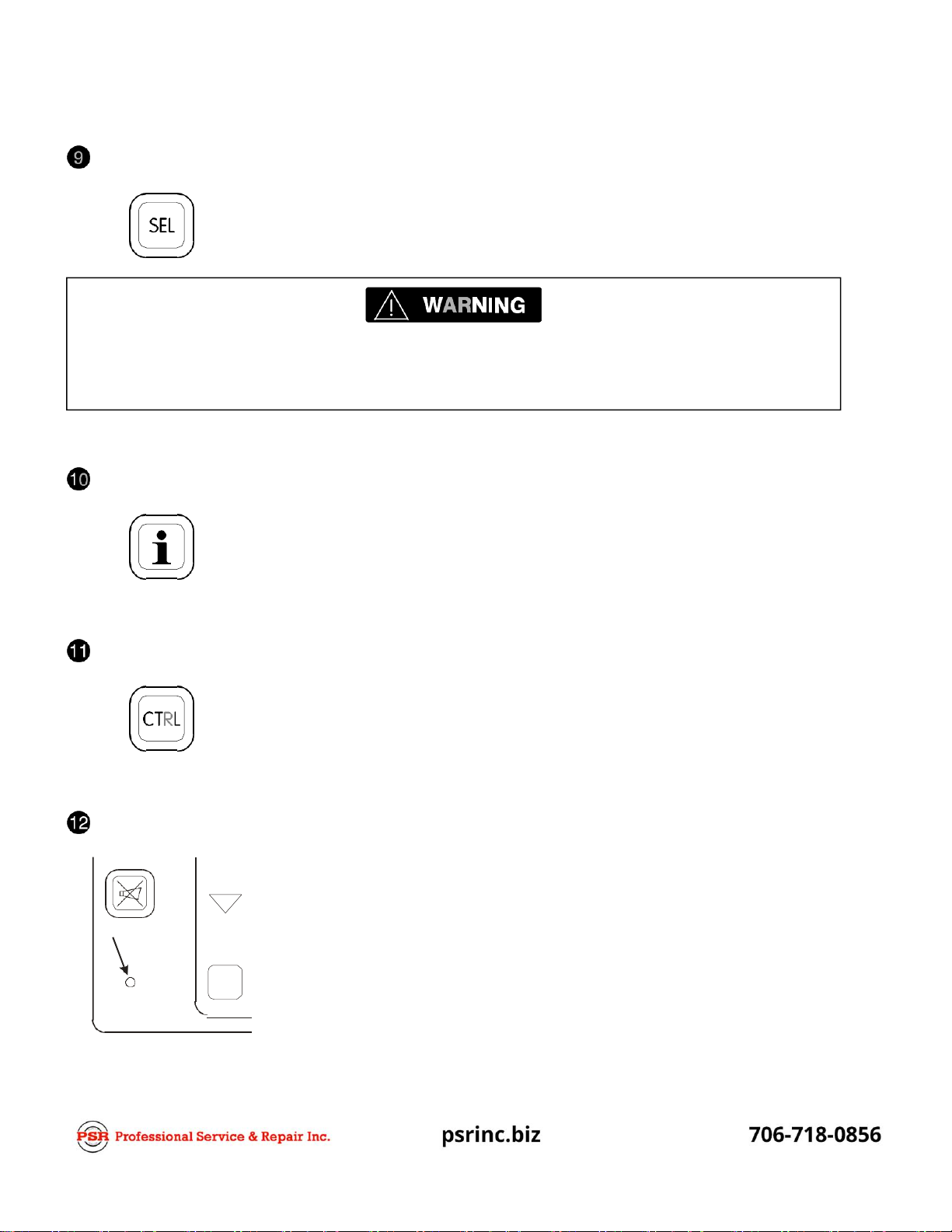
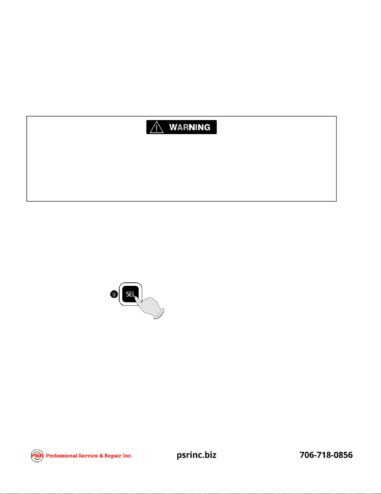
4 CONFIGURATION SETUP
The LMI setup procedure allows the operator to input the crane configuration using interactive
displays. The operator must complete the configuration setup procedure for the Load Moment
Indicator system by confirming (pressing OK) to set the system into operation or deleted (pressing
DEL) to enter a new configuration. The previous configuration setup will be displayed shown in bold
symbols and must match the current crane operating configuration.
Pile Driving Application
To prevent momentary cutout conditions due to spiking load indications that may occur or interfere
with the pile driving application, electrically disconnect the force transducer from the junction box and
install the bypass connector F9L0050 (031-300-060-252) in it’s place. Remove the force transducer
and replace with link J5M0216 in main pendant to replace the length of force transducer.
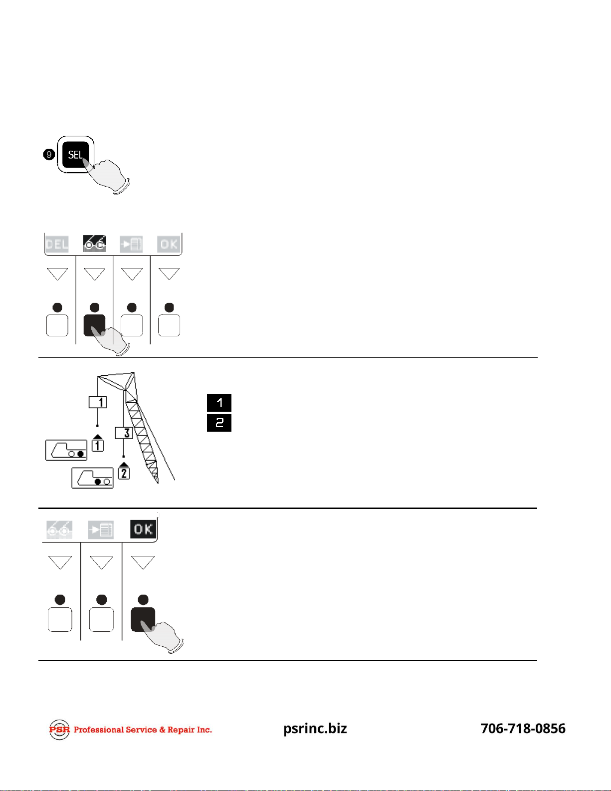
LMI Setup Procedure
...starts: manually after each modification of the crane configuration by
pressing "SEL" (9) button.
...is operated: by answering the different questions using functional buttons F1...F4
in accordance with the actual configuration of the crane.
...is cancelled: any time by pressing again the "SEL" (9) button. The system,
however, is only ready for operation, if the procedure has been
completed and the selections have been confirmed.

Operation, Calibration & Service Manual
LinkBelt - DS350 1334 Console
The correct setting is of utmost importance for the proper functioning of the system and the crane.
Therefore, only operators who are thoroughly familiar with the crane and the operation of the
system should execute the setting of the system according to the operating configuration of the
crane.
During the programming procedure the Load Moment Prewarning Light (3) and the Load Moment
Limit Light (2) will light up and the crane functions will be interrupted.
The LMI programming procedure consists of the following steps:
setting the boom type configuration
setting the counterweight configuration
setting lower configuration
specify boom / setting the hoist configuration and reevings
selecting the pick point
confirmation of the programming procedure
For easy operation, the computer guides the operator through the procedure step by step. (interactive
operation)
Definition of the Displayed Symbols:
The following illustrations define the symbols appearing on the display during the setup procedure for
your crane. Not all symbols will be shown, depending on the crane model and the answers to the
questions.
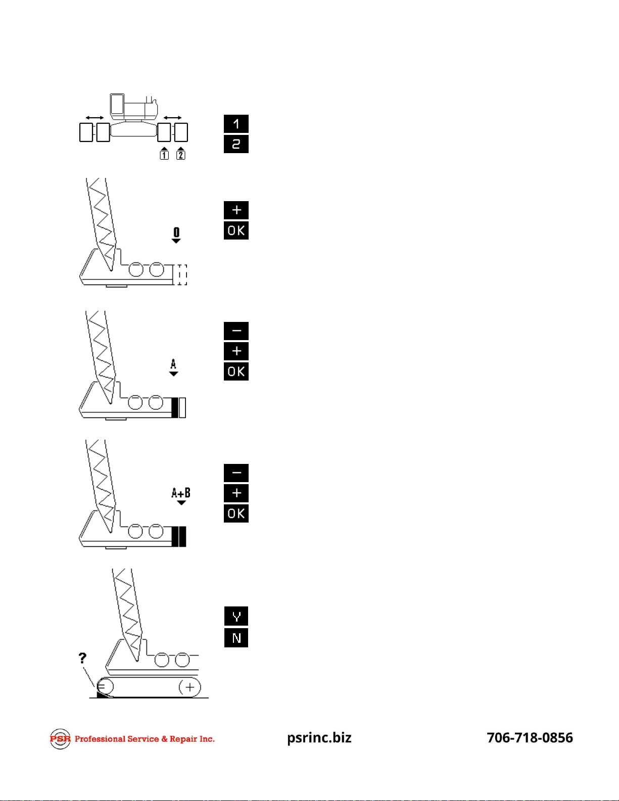
Setting the boom type configuration
main boom operation
tip extension operation
jib operation
Operation, Calibration & Service Manual
LinkBelt - DS350 1334 Console
Setting the crawler / counterweight configuration
Retracted crawlers
Extended crawlers
increase counterweight
confirm counterweight
Note: During the programming procedure this picture may be
skipped depending on previous selection (i.e. boom
selection or crawler position)
decrease counterweight
increase counterweight
confirm counterweight
Note: During the programming procedure this picture may be
skipped depending on previous selection (i.e. boom
selection or crawler position)
decrease counterweight
increase counterweight
confirm counterweight
with additional over end block
without additional over end block

Operation, Calibration & Service Manual
LinkBelt - DS350 1334 Console
Specify boom / jib lengths (example jib):
Select jib length:
Select jib offset:
Select main boom length:
decrease jib length
increase jib length
confirm jib length selection
5jib offset
17. 5jib offset
30 jib offset
increase main boom length
decrease main boom length
confirm main boom length
selection
Setting the hoist configuration and reeving (example jib)
Set front hoist drum pick
point: select pick point 1
select pick point 2
no use of front hoist drum

Operation, Calibration & Service Manual
LinkBelt - DS350 1334 Console
Select front hoist reeving: decrease reeving
increase reeving
confirm reeving
Note: During the programming procedure
this picture may be skipped depending on
previous selection (i.e. front hoist not used)
Set rear hoist drum pick
point: select pick point 1
select pick point 2
no use of rear hoist drum
Select rear hoist reeving: decrease reeving
increase reeving
confirm reeving
Note: During the programming procedure
this picture may be skipped depending on
previous selection (i.e. rear hoist not used)

Operation, Calibration & Service Manual
LinkBelt - DS350 1334 Console
At the end of the procedure all selections are represented once again in symbolic forms.
If selections have been made, the corresponding symbols are filled black (i.e. hoist
drums).
Once you have set the pick-points, you can switch between them by selecting which hoist drum is in
use:
Select hoist-in-use (example jib)
Hoist-in-use
selection: use pick point 1 as defined above
use pick point 2 as defined above
Under each pick point that you had set, you will find a symbol of the crane with the corresponding
hoist drum filled in black.
Confirmation of the programming procedure
Hoist-in-use quick selection
(chapter 4.2)
crawler position quick selection
(chapter 4.3)
cancel procedure
confirm inputs
Operation, Calibration & Service Manual
LinkBelt - DS350 1334 Console
Directly call function "Hoist-in-use quick selection".
F1
F2
F3
F4
Hoist-in-use quick selection
If, during the crane operation, the crane is switched over from using one hoist drum to the other, i.e.
from front to rear hoist drum, the LMI system has to be adjusted to this modification. This modification
can be entered without having to go through the whole LMI setup procedure again:
Call LMI setup procedure.
Select hoist in use (example):
use pick point 1 as defined
use pick point 2 as defined
Confirm modification.
(call up the function again if you have selected
the wrong hoist drum by mistake)
F2
F3
F4

Operation, Calibration & Service Manual
LinkBelt - DS350 1334 Console
Call LMI Programming Procedure.
Directly call function " Crawler Position Quick Selection".
F1
F2
F3
F4
Confirm modification.
(select again the function if you made a wrong selection)
F2
F3
F4
Crawler Position Quick Selection (if applicable)
If, during the crane operation, the position of the crawler tracks is changed, the LMI system has to be
adjusted to this modification. The input of the crawler tracks position can be carried out directly
without having to go through the whole LMI programming procedure again:
input of crawler position:
retracted crawlers
ex tended crawlers
Table of contents
Other PSR Industrial Equipment manuals

Popular Industrial Equipment manuals by other brands


Leroy-Somer
Leroy-Somer LSA 43.2 Installation and Maintenance

KTR
KTR RIGIFLEX-N Operating & assembly instructions

Cembre
Cembre RHTD410T Operation and maintenance manual

IEMCA
IEMCA KID 70 Manual for use and maintenance

Schako
Schako DKA-L-PPs-EL-Ex Additional operating instructions

Jerguson
Jerguson 300L Series Installation, Operation & Maintenance Instruction Manual


