PT W89730 User manual

A/C MANIFOLD GAUGE SET
OWNER'S MANUAL
Item Number W89730
WARNING
TO PREVENT EXPLOSION, SERIOUS
INJURY, AND DEATH:
• Service of air conditioning systems must
be done only by trained and experienced
technician to avoid overlling.
• T
echnicians opening refrigeration circuit in
automotive air conditioning systems MUST be
certied in refrigerant recovery and recycling
procedures in compliance with section 609
of Clean Air Act Amendments of 1990. For
additional information regarding ozone depletion
and air conditioning service regulations, visit
EPA’s website: www.epa.gov/ozone
WARNING: USE ONLY R-134A REFRIGERANT
WITH THE A/C MANIFOLD GAUGE SET
WARNING: READ, UNDERSTAND AND FOLLOW ALL INSTRUCTIONS AND WARNINGS BEFORE
OPERATING THIS TOOL. FAILURE TO DO SO MAY RESULT IN PERSONAL INJURY AND/OR
PROPERTY DAMAGE AND WILL VOID WARRANTY.

1. Keep work area clean and well lit.
2. Keep children away. Children must never be allowed in the work
area. Do not let them handle the A/C Manifold Gauge Set.
3. There are certain applications for which this A/C Manifold Gauge
Set was designed. It will do the job better and more safely at the rate
for which it was intended. Do not modify this A/C Manifold Gauge Set
and do not use this A/C Manifold Gauge Set for a purpose for which it
was not intended.
4. Dress properly. Do not wear loose clothing or jewelry as they can
be caught in moving engine parts. Protective clothes and nonskid
footwear are recommended when working. Wear restrictive hair
covering to contain long hair.
5.
Wear ANSI-approved impact safety goggles and heavy-duty work
gloves at all times during setup and use.
6. Do not overreach. Keep proper footing and balance at all times.
7. Maintain gauge with care. Keep the A/C Manifold Gauge Set clean
for better and safer performance. Inspect hoses periodically, and if
damaged, have them repaired by a qualied technician.
8. Stay alert. Watch what you are doing, use common sense. Do not
operate gauge when you are tired.
9. Check for damaged parts. Before using any gauge, any part that
appears damaged should be carefully checked to determine that it
will operate properly and perform its intended function. Check for
alignment and binding of moving parts; any broken parts or mounting
xtures; and any other condition that may affect proper operation.
Any part that is damaged should be properly repaired or replaced by
a qualied technician.
10. Replacement parts and accessories. When servicing, use only
identical replacement parts. Use of any other parts will void the
warranty. Only use accessories intended for use with this gauge.
11. Do not operate gauge if under the inuence of alcohol or drugs.
Read warning labels if taking prescription medicine to determine if
your judgment or reexes are impaired while taking drugs. If there is
any doubt, do not operate the gauge.
12.
Maintenance. For your safety, service and maintenance should be
performed regularly by a qualied technician.
13.
Industrial applications must follow OSHA requirements.
14. People with pacemakers should consult their physician(s) before
using this product. Electromagnetic elds in close proximity to a heart
pacemaker could cause interference to or failure of the pacemaker.
In addition, people with pacemakers should observe the following:
Caution is necessary when near the coil, spark plug cables, or
distributor of a running engine.
15. The warnings, cautions, and instructions discussed in this
instruction manual cannot cover all possible conditions and situations
that may occur. It must be understood by the operator that common
sense and caution are factors, which cannot be built into this product,
but must be supplied by the operator.
16. ONLY USE REFRIGERANT R-134a WITH THIS A/C MANIFOLD
GAUGE SET.
17. Do not start an engine in an enclosed area (like a garage).
A running gasoline engine generates carbon monoxide; carbon
monoxide is a colorless, odorless gas that can cause serious injury
and death, if inhaled.
18. Keep hands away from the moving parts and hot parts of
vehicle’s engine.
19. Read and understand all instructions and safety precautions
as outlined in the vehicle manufacturer’s manual for air condition
servicing. Only qualied mechanics that are trained in servicing air
conditioning systems should use this product.
20. When warming up an engine in preparation for checking of the
A/C system, make sure the vehicle’s transmission is placed in “Park”
and the emergency brake is applied.
21. Refrigerant can cause severe frostbite if it comes in contact with
skin. Follow the safety warnings and instructions provided by the
refrigerant manufacturer.
22. Do not disconnect any pressurized hose. Pressurized refrigerant
can cause severe injury.
23. Use caution when opening an air conditioning system line or
can of refrigerant. When checking, always place a towel around the
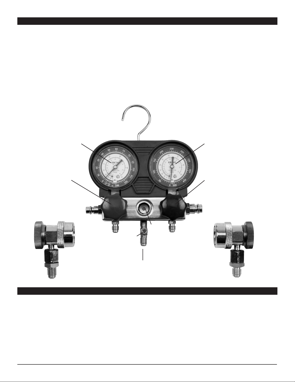
service valves of the air conditioning unit and Red and Blue Couplers
(22 and 23).
24.
Keep refrigerant away from excessive heat as pressure in the
container could increase enough to rupture the can.
25.
Do not discharge refrigerant into the atmosphere. Capture
refrigerant into an approved recovery container (not included),
and then dispose of properly. Contact your local Hazardous Waste
Authority for disposal guidelines.
26. Only use refrigerant in a manner consistent with the air
conditioning system’s repair manual.
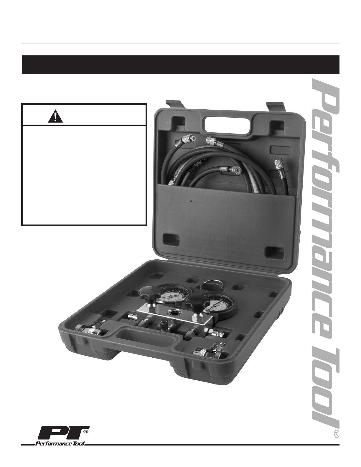
Blue (Low) Gauge............................................................................................................................................... 0-120 PSI
Blue Hose ............................................................................................................................................. 1/4 in. FFL x 50 in.
Red (High) Gauge .............................................................................................................................................. 0-500 PSI
Red Hose.............................................................................................................................................. 1/4 in. FFL x 50 in.
Yellow Hose .......................................................................................................................................1/2 in. ACME x 50 in.
Gauge Accuracy ........................................................................................................................................................+/-2%
SPECIFICATIONS:
Specifications are subject to change without notice.
This instruction manual is intended for your benefit. Please read and follow the safety, installation, maintenance and troubleshooting steps described within to ensure
your safety and satisfaction. The contents of this instruction manual are based upon the latest product information available at the time of publication. The
manufacturer reserves the right to make product changes at any time without notice.
SAFETY GUIDELINES / DEFINITIONS
WARNING: Read and understand this entire instruction manual before attempting to assemble, install, operate or maintain
this product. Failure to comply with the instructions may result in serious personal injury and/or property damage!
The following signal words are used to emphasize safety warnings that must be followed when using this product:
DANGER:
Indicates an imminently hazardous situation
that, if not avoided, WILL result in death or serious injury.
WARNING:
Indicates a potentially hazardous situation that,
if not avoided, COULD result in death or serious injury.
CAUTION:
Indicates a potentially hazardous situation that,
if not avoided, MAY result in minor or moderate injury.
NOTICE: Indicates important information, which if not
followed, MAY cause damage to equipment.
SAFETY GUIDELINES / DEFINITIONS

1. The Red HP Gauge (3) is used to measure high pressure compressor discharge side pressure.
2. The Blue LP Gauge (5) is used to measure low-pressure side suction or pressure.
3. The Manifold Valves (11) control the ow of refrigerant to and from the Yellow Hose (18), also called the Charge Hose.
4. The Coupler Valves (22,23) control the ow to the Gauges (3, 5) from the Red and Blue Hoses (17,19).
5. The Sight Glass (13) allows checking the appearance of the refrigerant.
6. The Yellow Hose (18), also called Charge Hose can be used three ways:
a. Refrigerant recovery/evacuation.
b. Charging (lling) the system.
c. For checking, attach the Yellow Hose (18) to both branches of the T-tting (16) to reduce the risk of leaks.
7. The charge valve allows for simultaneous connection of a refrigerant recovery system.
8. General instructions for A/C service are outlined in this manual. Specic procedures for each individual system type
and model should be referenced in the vehicle manufacturer’s specic A/C system service manual.
9. See Operation instructions that follow.
LOW-PRESSURE HIGH-PRESSURE
(LP) BLUE SIDE (HP) RED SIDE
Charge
Valve
Blue
Coupler
Storage
Plug (6)
Blue
Coupler
(23)
Red
Coupler
(22)
Red
Coupler
Storage
Plug (7)
Red HP
Gauge (3)
Blue LP
Gauge (5)
Red HP
Manifold
Valve
Blue LP
Manifold
Valve
Yellow Charge Hose
Connector (16)
Red HP Hose
Connector
Blue LP Hose
Connector
Sight
Glass
(13)
COMPONENTS AND FUNCTIONS
OPERATION
Read the ENTIRE SAFETY WARNINGS section at the beginning of this manual before set up or use of this product.
WARNING:
TO PREVENT EXPLOSION, SERIOUS INJURY, AND DEATH: Service of air conditioning systems must be done
only by trained and experienced technician to avoid overlling. Technicians opening refrigeration circuit in automotive air
conditioning systems MUST be certied in refrigerant recovery and recycling procedures in compliance with section 609
of Clean Air Act Amendments of 1990. For additional information regarding ozone depletion and air conditioning service
regulations, visit EPA’s website: www.epa.gov/ozone
WARNING:
TO PREVENT SUDDEN LOSS OF CONSCIOUSNESS, AND DEATH: Connect and use in a well ventilated area
ONLY. Refrigerant can displace air if allowed to accumulate, causing sudden loss of consciousness followed by death. This
can happen WITHOUT FEELING SHORTNESS OF BREATH.
2

Coupler Valve (22, 23) operation:
CCW = Close
CW = Open
WARNING:
TO PREVENT EXPLOSION, SERIOUS INJURY, AND DEATH: Do not open the red HP Manifold Valve unless
requested to do so during the recovery/evacuation procedure. Refrigerant is under great pressure. Attempting to add
refrigerant through the HP side of the system may cause the refrigerant can to explode.
Note: Throughout this manual:
HP means High-pressure
LP means Low-pressure
CW means Clockwise
CCW means Counterclockwise
Note: Procedures such as charging refrigerant through the HP side of the system and adding lubricant to the system are
beyond the scope of this manual.
Note: For additional information regarding the parts listed in the following pages, refer to the Assembly Diagram near the
end of this manual.
OPERATION CONTINUED
Manifold Valve (11) operation:
CW = Close
CCW = Open
WARNING:
To prevent SERIOUS INJURY and DEATH:
1. Wear ANSI-approved safety goggles and heavy-duty work gloves during setup and use.
2. DO NOT OPEN either Manifold Valve (11) unless directed to do so; otherwise, refrigerant leaks, A/C system
contamination, and hazardous expulsion of pressurized refrigerant may occur.
3. Use in well-ventilated area only.
4. Keep gauge and hoses away from moving engine parts.
5. Turn off vehicle’s engine and A/C system before attaching gauge.
6. The following procedure is to be performed only by a technician certied in refrigerant recovery and recycling
procedures, as explained previously.
3

1. Close both Manifold Valves (11) by turning CW.
Close both Coupler Valves (22, 23) by turning CCW.
2. CONNECT HOSES:
a. Connect one end of the Blue Hose (19) to the
Blue LP Hose Connector and the other end to the
Blue Coupler (23).
b. Connect one end of the Red Hose (17) to the Red
LP Hose Connector and the other end to the Red
Coupler (22).
c. Connect one end of the Yellow Hose (18) to the
Yellow Charge Hose Connector (16) and the other
end to the Charge Valve on that Connector.
3. ATTACH COUPLERS:
a. Attach the Blue Coupler (22) to the suction LP port
on the A/C system.
b. Attach the Red Coupler (23) to the discharge HP
port on the A/C system.
4. PERFORM CHECK:
a. To do a dynamic check: Turn on the vehicle and
allow it to reach normal operating temperature.
Then, turn on the A/C system.
b. Open both Coupler Valves (22, 23) by turning CW.
c. Read the pressure on both of the Gauges (3, 5)
and compare to the manufacturer’s recommended
readings.
5. AFTER:
a. Close both Coupler Valves (22, 23)
by turning CCW.
b. Turn off the vehicle and the A/C system if dynamic
check was done.
c. Carefully disconnect the Couplers (22,
23), the
hoses may contain residual refrigerant. Pull back
the knurled ring on each Coupler (22, 23) and store it
on its Coupler Storage Plug (6, 7).
CW
KEEP
CLOSED
KEEP
CLOSED
CW
CWCW
REDBLUE
YELLOW
To charge
valve
To discharge
HP port
To suction
LP port
DIAGNOSTIC CHECK
RECOVERY / EVACUATION
1. Close both Manifold Valves (11) by turning CW. Close
both Coupler Valves (22, 23) by turning CCW.
2. CONNECT HOSES:
a. Connect one end of the Blue Hose (19) to the Blue
LP Hose Connector and the other end to the Blue
Coupler (23).
b. Connect one end of the Red Hose (17) to the Red
LP Hose Connector and the other end to the
Red Coupler (22).
c. Connect one end of the Yellow Hose (18) to the
Yellow Charge Hose Connector (16) and the other end
to the refrigerant recovery system / vacuum pump.
3. ATTACH COUPLERS:
a. Attach the Blue Coupler (22) to the suction LP port
on the A/C system.
b. Attach the Red Coupler (23) to the discharge HP port
on the A/C system.
4. PERFORM RECOVERY / EVACUATION:
a. Turn on the refrigerant recovery system / vacuum
pump.
b. Open both Coupler Valves (22, 23) by turning CW
and both Manifold Valves (11), turning them CCW.
c.
Read the amount of vacuum on the Blue LP Gauge (5).
4

1. Close both Manifold Valves (11) by turning CW. Close
both Coupler Valves (22, 23) by turning CCW.
2. CONNECT HOSES:
a. Connect one end of the Blue Hose (19) to the
Blue LP Hose Connector and the other end to the
Blue Coupler (23).
b. Connect one end of the Red Hose (17) to the Red
LP Hose Connector and the other end to the Red
Coupler (22).
c. Connect one end of the Yellow Hose (18) to the
Yellow Charge Hose Connector (16) and the other
end to refrigerant supply.
KEEP THE CAN/CYLINDER UPRIGHT.
3. ATTACH COUPLERS:
a. Attach the Blue Coupler (23) to the suction LP port
on the A/C system.
b. Attach the Red Coupler (23) to the discharge HP
port on the A/C system.
4. PERFORM CHARGING:
a.
Turn on the vehicle and allow it to come up to normal
operating temperature. Then, turn on the A/C system.
b. Open the Blue Coupler Valve (23) only by turning
CW and Blue Manifold Valve (11), turning it CCW.
5. AFTER:
a. After charging manufacturer recommended
amount of R-134a, close both Coupler Valves (22,
23) by turning CCW.
b. Turn off the vehicle and the A/C system.
c.
Carefully disconnect the Couplers (22, 23) from
the A/C system, the hoses may contain residual
refrigerant. Pull back the knurled ring on each Coupler
(22, 23) and store it on its Coupler Storage Plug
(7 & 6, respectively).
TURN VALVES AS SHOWN ONLY AFTER MAKING ALL
CONNECTIONS AND TURNING ON REFRIGERANT
RECOVERY SYSTEM / VACUUM PUMP
CCW
CWCW
REDBLUE
YELLOW
To refrigerant recovery
system / vacuum pump
To discharge
HP port
To suction
LP port
CCW
TURN VALVES AS SHOWN ONLY AFTER MAKING
ALL CONNECTIONS
CCW
CWCW
REDBLUE
YELLOW
To R-134a refrigerant supply
To discharge
HP port
To suction
LP port
KEEP
CLOSED
CW
5. AFTER:
a. Shut off the refrigerant recovery system / vacuum
pump when the vacuum level reaches the
manufacturer’s recommended level.
b. Close both Coupler Valves (22, 23) by turning
CCW.
c. Disconnect the Couplers (22, 23) from the A/C
system. Pull back the knurled ring on each Coupler
(22, 23) and store it on its Coupler Storage Plug
(7 & 6, respectively).
DIAGNOSTIC CHECK CONTINUED
CHARGING

CARE AND MAINTENANCE
1 Rubber Cover........................................................... 1
2 Manifold Body.......................................................... 1
3 Red HP Gauge......................................................... 1
4 Hook ........................................................................ 1
5 Blue LP Gauge......................................................... 1
6 Blue Coupler Storage Plug ...................................... 1
7 Red Coupler Storage Plug....................................... 1
8 Valve Seat................................................................ 2
9 Valve Stem............................................................... 2
10 Valve Nut.................................................................. 2
11 Manifold Valve.......................................................... 2
12 O-Ring...................................................................... 2
13 Sight Glass............................................................1
14 Ring Nut ................................................................1
15 Connector .............................................................2
16 T-Connector ..........................................................1
17 Red Hose (HP Refrigerant)...................................1
18 Yellow Hose (HP Refrigerant) ...............................1
19 Blue Hose (LP Refrigerant)...................................1
20 Connector .............................................................2
21 O-Ring...................................................................2
22 Red Coupler (HP) .................................................1
23 Blue Coupler (LP) .................................................1
No. Description Qty. No. Description Qty.
TO PREVENT SERIOUS INJURY FROM TOOL
FAILURE: Do not use damaged equipment. If
abnormal noise, vibration, or leaking air occurs, have
the problem corrected before further use.
1. Before each use, inspect the general condition of
the A/C Manifold Set. Check for cracked or
broken parts, damaged Hoses (17,18,19), and
any other condition that may affect safe operation.
If a problem with the Set occurs, have it corrected
before further use.
Do not use damaged equipment.
2. Periodically, clean with a damp cloth using a mild
detergent or solvent.
3. When storing, keep the set clean and dry. Also,
connect the Red Coupler (22) and the Blue
Coupler (23) to its corresponding Coupler Storage
Plug (7 or 6 respectively) to prevent contamination.
EXPANDED PARTS LIST
HP means High-Pressure LP means Low-Pressure
PLEASE READ THE FOLLOWING CAREFULLY
THE MANUFACTURER AND/OR DISTRIBUTOR HAS
PROVIDED THE PARTS LIST AND ASSEMBLY DIAGRAM IN
THIS MANUAL AS A REFERENCE TOOL ONLY. NEITHER
THE MANUFACTURER OR DISTRIBUTOR MAKES ANY
REPRESENTATION OR WARRANTY OF ANY KIND
TO THE BUYER THAT HE OR SHE IS QUALIFIED TO
REPLACE ANY PARTS OF THE PRODUCT. IN FACT, THE
MANUFACTURER AND/OR DISTRIBUTOR EXPRESSLY
STATES THAT ALL REPAIRS AND PARTS REPLACEMENTS
SHOULD BE UNDERTAKEN BY CERTIFIED AND LICENSED
TECHNICIANS, AND NOT
BY THE BUYER.
THE BUYER ASSUMES ALL RISKS AND
LIABILITY ARISING OUT OF HIS OR HER
REPAIRS TO THE ORIGINAL PRODUCT
OR REPLACEMENT PARTS THERETO,
OR ARISING OUT OF HIS OR HER
INSTALLATION OF REPLACEMENT
PARTS THERETO.
6

LIMITED WARRANTY
PERFORMANCE TOOL® extends only the following warranties, and only to original retail purchasers. These warranties give specific legal rights.
Except where prohibited by local law, the law of the State of Washington governs all warranties and all exclusions and limitations of warranties and
remedies. There may be other rights which vary from state to state.
PERFORMANCE TOOL® warrants the product to be free from defects in materials and workmanship under normal use and service. A defective
product may be returned for a free replacement within 90 days from the date of purchase, provided that product is returned to place of purchase
immediately after discovery of defect. After 90 days and up to one year from date of purchase, PERFORMANCE TOOL® will replace at no charge
any parts which our examination shall disclose to be defective and under warranty. These warranties shall be valid only when a sales receipt
showing the date of purchase accompanies the defective product or defective part (s) being returned. For part (s) after 90 days, please remit your
request, postage prepaid to:
PERFORMANCE TOOL, P.O. Box 88259 Tukwila, WA 98138
These warranties exclude blades, bits, punches, dies, bulbs, fuses, hoses, and other consumables which must be replaced under normal use and
service. These warranties shall not apply to any product or part which is used for a purpose for which it is not designed, or which has been repaired
or altered in any way so as to affect adversely its performance or reliability, nor shall these warranties apply to any product or part which has been
subject to misuse, neglect, accident or wear and tear incident to normal use and service.
PERFORMANCE TOOL® does not authorize any other person to make any warranty or to assume any liability in connection with its products.
Except for warranties of title and the limited express warranties set forth above, PERFORMANCE TOOL® makes no express or implied warranties
of any kind with respect to its products. In particular, PERFORMANCE TOOL® makes no implied warranty of merchantability and no implied
warranty of fitness for any particular purpose, except that for goods purchased primarily for personal, family or household use and not for
commercial or business use, PERFORMANCE TOOL® makes an implied warranty of merchantability (and, if otherwise applicable, an implied
warranty of fitness for a particular purpose), but only for the particular qualities or characteristics, and for the duration, expressly warranted above.
The laws on limitation of implied warranties may differ from state to state, so the above limitations may not apply in all cases.
PERFORMANCE TOOL® shall not be liable for consequential, incidental or special damages resulting from or in any manner related to any product,
or to the design, use, or any inability to use the product. The sole and exclusive remedy for a defective product or part shall be the repair, or
replacement thereof as provided above. The laws on limitation of remedies or on consequential, incidental or special damages may vary from state
to state, so the above limitations may not apply in all cases.
© Copyright 2019 WILMAR CORPORATION, P.O. Box 88259 Tukwila, WA 98138
Table of contents
Other PT Measuring Instrument manuals
Popular Measuring Instrument manuals by other brands

Keller
Keller LEO 5 operating instructions

MOBILE-ALERTS
MOBILE-ALERTS pro Series quick reference

COMAC CAL
COMAC CAL CALOR 38 Installation and technical conditions

Parkside
Parkside PWM 4 A1 operating instructions

Ivoclar Vivadent
Ivoclar Vivadent bluephase operating instructions

Knick
Knick Stratos PROFIBUS 2221X Cond user manual