- 1-
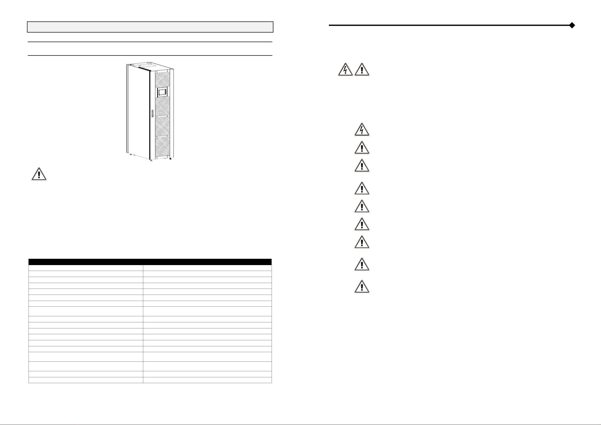
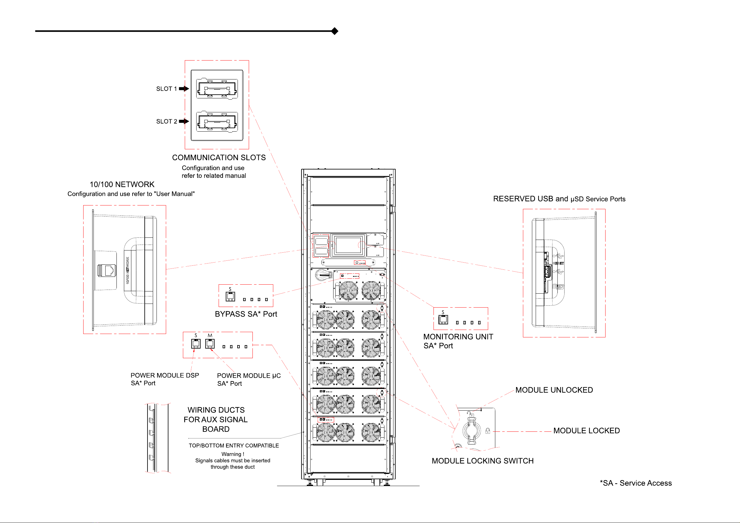
Maxsis RXR130
READ "SAFETY MANUAL" BEFORE STARTING
THE MODULAR UPS POWER CABINET INSTALLATION
INSTALLATION ENVIRONMENTS
The Modular UPS Power Cabinet is manufactured for an internal environment.
Essential Requirements:
- avoid dusty environments;
- the relative humidity must comply with the data in the table within this page;
- the operating ambient room temperature must comply with the data in the table within this page;
- avoid environments exposed directly to sunlight and hot air.
To regulate the ambient temperature within the UPS location at the appropriate range, waste heat disposal
systems must be used. Methods which can be used include:
- natural ventilation;
- forced ventilation, recommended if the external temperature is lower (e.g. 20°C) than the temperature at
which you want to operate the UPS;
- air conditioning system, recommended if the external temperature is higher (e.g. 30°C) than the
temperature at which you want to operate the UPS.
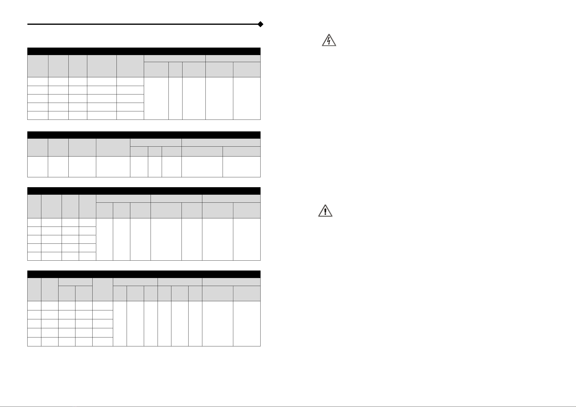
MAIN INFORMATION TABLE
Power [kVA / kW] 125 / 125
V Input [V] 380 – 400 – 415 (3PH + N)
Frequency Input [Hz] 50 - 60
V Output [V] 380 – 400 – 415 (3PH + N)
Frequency Output [Hz] 50 / 60
Operating temperature [°C] 0 ÷ 40
Max relative humidity in operation [%] 90% (without condensation)
Max installation height 1000 mt at nominal power
(-1% power for every 100 m above 1000 m) – max 4000 m
Power loss @ 100% load (1) 5.9 kW - 5073 kcal/h – 20130 BTU/h
Power loss @ 50% load (1) 2.7 kW - 2322 kcal/h – 9220 BTU/h
Max Leakage Current [mA] (2) 550
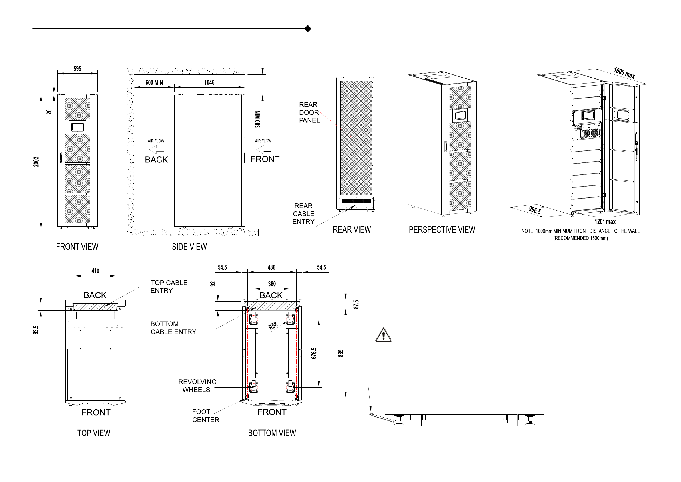
Cabinet Dimension (WxDxH) [mm] 595x1046x2002
Shipping Dimension (WxDxH) [mm] 700x1166x2174
Shipping Weight Power Cabinet [kg] 260
Net Weight without power modules / Bypass module
Included [kg] 240
TOTAL Net Weight with 5 power modules / Bypass module
Included [kg] 420
Air Flow [m3/h] 2710
Degree of protection IP20
(1) 3.97 BTU / h = 1 kcal / h
(2) The load leakage current is added to the one of the UPS on the ground protection conductor
PRELIMINARY INFORMATION FOR INSTALLATION
ALL OPERATIONS DESCRIBED IN THIS SECTION MUST BE PERFORMED BY QUALIFIED AND TRAINED
PERSONNEL ONLY.
Our Company assumes no liability for damages caused by incorrect connections or operations not
contained in this manual.
The following operations have to be performed with the UPS disconnected from the power mains, off
and with all equipment switches open.
Before making the connection, open all cabinet switches and verify that the UPS is completely
isolated from power sources: battery and AC power line. In particular, check that:
- the UPS input line is completely disconnected
- the UPS bypass line is completely disconnected
- the external UPS battery line switch/fuses are open
- all UPS switches are in the open position
- check with a multimeter that there are no dangerous voltages
The first connection to be made is the protective conductor (earth wire), this must be connected to
the bar marked as PE.
The UPS must operate while connected to the earthing system.
The input Neutral must always be connected.
ATTENTION: a three-phase four-wire distribution system is required.
The standard UPS version must be connected to a 3 Phase + Neutral + PE (ground protection) power
line.
Comply with clockwise phase rotation.
Read the battery box manual before connecting the batteries.
Check that the total battery voltage meets the requirements of the UPS (refer to the Battery Box
nameplate).
ATTENTION: the maximum length of the connection cables to the Battery Box is 10 meters.
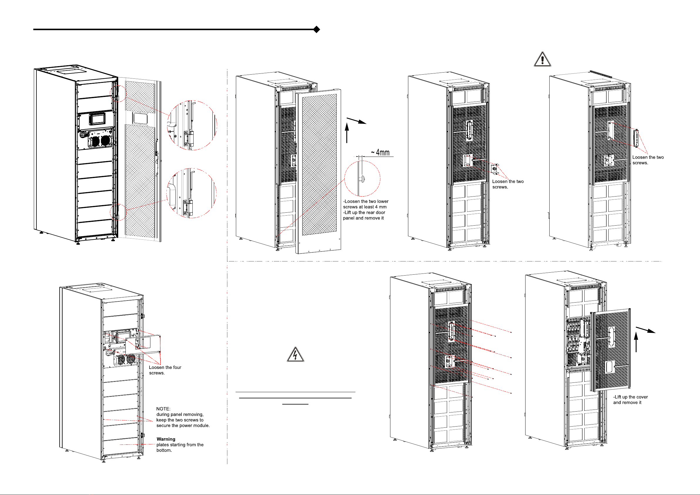
ATTENTION: After the installation operation is complete, refit the cabinet protection panels using the
appropriate screws.
ELECTROMAGNETIC COMPATIBILITY
WARNING: This is a category C2 UPS product. In a residential environment, this product may cause
radio interference, in which case the user may be required to take additional measures.
BATTERY ROOM VENTILATION
The room where the battery box is located must have enough ventilation to ensure the concentration
of hydrogen produced is within safe limits.
The room should preferably be ventilated naturally; if it cannot be, forced ventilation may be
employed.
Standard EN 50272-2 regarding air exchange provides that the minimum aperture must satisfy the
following equation:
A = 28 x Q = 28 x 0.05 x n x Igas x C10 (1/10³) [cm²] where:
A = area of opening [cm²]
Q = airflow required [m³/h]
n = number of battery cells;
C10 = battery capacity in 10 hours [Ah]
Igas = gas producing current [mA/Ah]
according to the standard:
Igas = 1 in backup charging for VRLA type batteries
Igas = 8 in fast charging for VRLA type batteries
NOTE: read the User Manual before using the Maxsis RXR.
NOTE: some images contained in this document are for information purposes only and may not faithfully
demonstrate the parts of the product they represent.