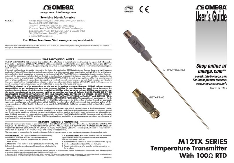
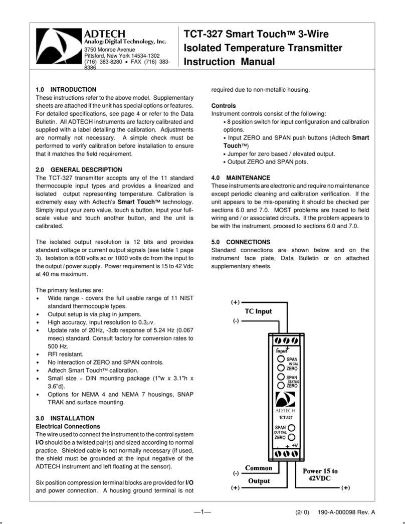
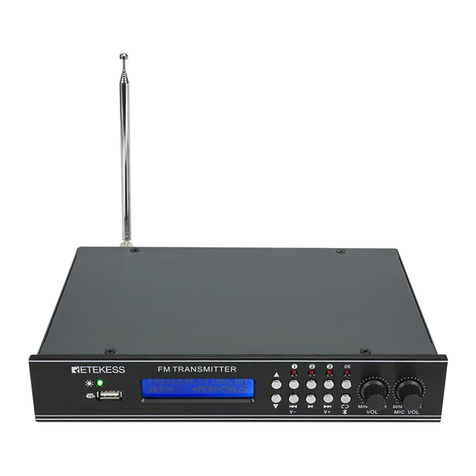
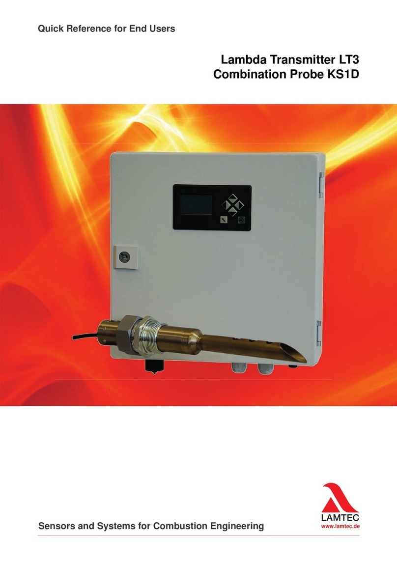
Metal Samples MS2901E User manual

MS2901E
High Resolution ER 4-20mA HART Transmitter
Operator’s
Manual
Metal Samples Company
A Division of Alabama Specialty Products, Inc.
152 Metal Samples Rd., Munford, AL 36268 Phone: (256) 358-4202 Fax: (256) 358-4515


Table of
Contents
I.Introduction..............................................................................................................................................1
A.GeneralDescription...................................................................................................................1
B.PrinciplesofOperation..............................................................................................................1
C.TechnicalSpecifications.............................................................................................................3
II.InstallationandOperation.......................................................................................................................4
A.ReceivingtheMS2901ETransmitter.........................................................................................4
B.Installation.................................................................................................................................4
1.PhysicalMountingandProbeConnection...................................................................4
a.Direct‐ProbeMounting......................................................................................5
b.RemoteMounting..............................................................................................5
2.CurrentLoopConnection.............................................................................................6
a.MakingConnections.........................................................................................6
b.Grounding.........................................................................................................6
c.WiringforaSafeAreaInstallation....................................................................6
d.HARTConnectionforaSafeAreaInstallation...................................................7
e.WiringforaHazardousAreaInstallation...........................................................8
f.WiringwithHARTatHazardouslocations..........................................................9
3.SetupandOperation.....................................................................................................10
a.ProbeSelectionSwitches..............................................................................10
b.TestingtheCurrentLoop..............................................................................11
i.Calibration...............................................................................................11
ii.Testingloopoutputzero(4mA)andspan(20mA).................................12
iii.TestingtheMS2901EwiththeMeterProver..........................................12
c.InterpretingData............................................................................................13
i.MetalLoss................................................................................................13
ii.CalculatingCorrosionRate.......................................................................14
d.Commissioning..............................................................................................16
C.Maintenance............................................................................................................................17
D.HARTCommunicationandDeviceDescriptor..........................................................................18
E.TheHARTModem.....................................................................................................................33
F.Troubleshooting........................................................................................................................37
III.ServiceandWarrantyInformation.......................................................................................................38
A.Warranty...................................................................................................................................38
B.ObtainingServiceandReturningtheInstrumentforRepair....................................................38
C.InstrumentRepairForm...........................................................................................................39
AppendixA–RevisionHistory...................................................................................................................40
AppendixB–HazardousAreaCertificationDetails...................................................................................41
AppendixC–ControlDrawing(HazardousAreaWiringDiagram)............................................................48


1
I.Introduction
A.GeneralDescription
TheMS2901Eisahigh‐resolutionmeterdesignedtotransmitcorrosion(metalloss)datafromanElectrical
Resistance(ER)probetoaplantcontrolsystemorotherrecordingdevice.TheMS2901Eutilizestraditional
4‐20mAcurrentloopcommunicationandHARTDigitalTransmission.Itisloop‐poweredwithbuilt‐in
isolator,soitrequiresonlyatwo‐wireinterface.Thisresultsinasimpleandlow‐costinstallation.Theuse
ofthe4‐20mAprotocolalsoallowstheMS2901Etobeplacedgreatdistancesfromthecontrolsystemor
recorderwhilemaintaininggoodnoiserejection.Practicalcurrentloopdistancescanbemanythousands
offeet(seepages6and7forexactspecifications).Also,HARTdigitaltransmissionhelpstoconnectthe
transmittertoHARTSystem/PC/Handheld.
TheMS2901EiscompatiblewithalltypesofMetalSamplesERprobes,aswellasanystandardERprobe
fromothermanufacturers.Unlikecompetitors’products,theMS2901ETransmitterdoesnotrequire
factorymodificationtoaccommodatedifferentprobetypes.Theprobetypecanbeeasilychangedatany
timeusingtheon‐boardprobeselectionswitches(seepage9.)
TheMS2901Eisavailableasdirect‐mount(standard)orremote‐mount.Inthedirect‐mountversionthe
MS2901EismounteddirectlytotheERprobe.Thisoptionoffersthesimplestinstallationandminimizes
noiseproblems.Theremote‐mountoptionallowstheMS2901Etobemountedindependentlyfrom(butin
closeproximityto)theERprobe.Itisthenconnectedtotheprobeviaashortprobecable.(Seepage5for
mountingdiagramsandspecifications.)
B.PrinciplesofOperation
TheMS2901EoperatesontheElectricalResistance(ER)techniqueandisusedinconjunctionwithanER
probe.TheERprobeutilizesaresistivesensingelementmanufacturedfromthematerialofinterest(ora
closeapproximation)whichisexposedtoacorrodingenvironment.ThisiscalledtheExposedorCorroding
Element.TheresistanceoftheExposedElementisdirectlyrelatedtoitsthickness,soastheelement
corrodestheresultinglossofmetalcausesaproportionalincreaseintheelement’sresistance.Theprobe
alsocontainsaninternalReferenceElementwhichisusedtocompensatefortheinfluencesof
temperatureontheExposedElement.
TheMS2901EisdesignedtoworkwithanystandardERprobe,butitisrecommendedthatCylindricaland
LargeFlushtypeprobesbeusedtoensureoptimumperformance.Theirphysicaldesignplacesthe
ReferenceElementincloserproximitytotheExposedElementcomparedtootherprobetypes,providing
moreeffectivetemperaturecompensationandthusreducingtheeffectsofthermalnoise.
Becausetheyaredesignedtocorrode,ERprobesaresacrificialinnature.EachERprobewillhaveafinite
lifethatisbasedontheelementthickness.ERprobesareavailableinanumberofgeometriesand
thicknessesdesignedtosuitawidevarietyofapplications.Table1liststhecommonERelementoptions
availablefromMetalSamplesandtheeffectivelifeofeach.

2
ElementTypeCompatibilityThicknessProbeLife
(Span)
TubularLoopCompatible
42
84
WireLoopCompatible
4010
8020
Flush(Small)Compatible
42
84
2010
CylindricalPreferred
105
2010
5025
Flush(Large)Preferred
52.5
105
2010
4020
Table1.StandardERProbeElements
TheMS2901EmeasuresanERprobeutilizingahigh‐resolution,16‐bitmeasurement.Thisallowsthe
MS2901Etodetectmuchsmalleramountsofmetalloss,thusrespondingfastertocorrosioneventsand
upsets(comparedtotraditionalERmeters.)At16‐bitresolutiontheMS2901Ecanmeasuremetalloss
amountsassmallas0.0015%oftheprobelife.
MetallossreadingstakenbytheMS2901Eareconvertedtoalinearized4‐20mAcurrentloopoutput.
The4‐20mAsignalcanbefedintoaplantcontrolsystemorotherdevicesandscaledaccordinglyto
reflectmetalloss.Thencorrosionratescanbecalculatedbasedonthemetallossdataovertime.Thisis
coveredinmoredetailonpages11and12.MoreinformationonERprobes,theirtheory,selection,and
usecanbefoundonourwebsiteat http://www.alspi.com/erintro.htm.

3
C.TechnicalSpecifications
PhysicalData
InstrumentWeight: 5.25lb.(2.38Kg)
TotalWeightw/Accessories:7.31lb.(3.31Kg)
InstrumentDimensions:9.0"Hx5.3"Wx5.0"D
(22.86cmHx13.46cmWx
12.70cmD)
OperatingTemperature:‐40°to158°F(‐40°to70°C)
StorageTemperature:‐40°to176°F(‐40°to80°C)
EnclosureMaterial:CastAluminum(Copper‐Free)
MountingSpecifications:Directprobemountor
Remotemount
(Uptoa2.5”(6.35cm)Dia.pole)
PerformanceData
MeasurementType:ERmeasurementusinganystandardERprobetype
(WireLoop,TubeLoop,Cylindrical,Flush,Strip,etc.)
Range:0‐100%ofprobelife
Resolution:0.0015%ofProbeLife(16‐bit)
CycleTime:1Minute
ElectricalData
Connection:4to20mAwithHART,2Wire
PowerRequirements:11to28VDC
CurrentConsumption:4to22.5mA
Maximum20mAwithoutalarm/22.5mAwithalarm
ElectricalConnection:½”NPTentrywithExGland
¾”orotherentriesareavailablewithadaptors*
MaximumProbeCableDistance:30ft(9.1m)
OutputData
OutputSignal:4‐20mAoutputwithHARTprotocol
AlarmSignal:‐CurrentOutputConfigurable
‐Digitalinterface
Load:‐min.250OhmsforHARTCommunication
HazardousLocationCertifications–IntrinsicSafety
EuropeandWorldwideExdb[iaGa]IICT6….T4Gb
(ATEXandIECEx)Extb[iaDa]IIICT85°C…T130°CDb
‐40°C≤Tamb≤+70°C
ATEXCertificateNo:ITS14ATEX27981XIECEx
CertificateNo:IECExITS14.0010X
USAandCanadaClassI,Zone1,AExdb[iaGa]IICT6….T4Gb
(ETL)ClassI,Division2,GroupsA,B,C&D,T6…T4
HazardousLocationCertifications–Enclosure
CaseSpecifications:ExplosionProof(FM,CSA,UL)
IP66,NEMA4X,7BCD,9EFG
IncludedAccessories(Direct‐MountModel)
MeterProver,OperationsManual
IncludedAccessories(Remote‐MountModel)
MeterProver,OperationsManual,ProbeCable,MountingHardwareKit

4
II.InstallationandOperation
A.ReceivingtheMS2901ETransmitter
ChecktheMS2901ETransmitterforanyshippingdamagewhenitisfirstreceived.WhentheMS2901E
isunpacked,verifythatthefollowingitemsareincluded:
MS2901ETransmitter
MeterProver
User’sManual
ProbeCable&MountingHardware(optional,forremote‐mountonly)
Intheeventofshippingdamage,quantityshortage,ormissingitems,itisrecommendedthattheevent
isdocumentedimmediatelyandthatdigitalphotographsaretaken.Anyshortagesormissingitems
shouldbereportedtoMetalSamplesimmediately.Intheeventofshippingdamage,aclaimshouldbe
openedwiththeresponsiblecarrier.
B.Installation
Warning:Donotopenwhenanexplosiveatmosphereispresent.Potentialelectrostaticcharginghazard.
Seeinstructions.Referusemanualforinstallationinstructionsandmaximumelectricalinput&output
parameters.
Attention:nepasouvrirenprésenced'uneatmosphèreexplosive.Risquepotentieldecharge
électrostatique.Voirlesinstructions.Consultezlemanueld'utilisationpourlesinstructionsd'installation
etlesparamètresd'entréeetdesortieélectriquesmaximum.
InstallationoftheMS2901ETransmitterinvolvesthefollowingsteps:
1. PhysicalMounting
2. ElectricalConnection
3. SetupandProgramming
1.PhysicalMountingandProbeConnection
WhenselectingalocationtomounttheMS2901Eitisimportanttoconsiderthesurrounding
environment.Toensureproperoperation:
DonotmounttheMS2901Einalocationthatexceedsitsoperatingtemperature.
AvoidmountingtheMS2901Enearsourcesofstrongelectricalnoise.
Ensurethatthereissufficientclearanceforinstallationandtoopenthetransmittercover
afterwards.
a.Direct‐ProbeMounting
TheMS2901Eisdesignedfordirect‐probemountingwhicheliminatestheneedforadditionalhardware
andtransmitter‐to‐probecabling.Thisgreatlysimplifiesinstallation,reducescosts,andminimizes
electricalnoisethatcanbecoupledontoprobecablingfromnearbyelectricalequipment.
BeforemountingtheMS2901E,firstensurethattheprobeisinstalledproperlyandsecurely.During
installationitisimportantthatyoudonotapplyexcessiveforceontheprobeorseals,asdoingsocould
breakthesealandresultinsystemleakage.

5
TomounttheMS2901E:
1. Alignthekeywaysofthetransmitterandprobeconnectors.
2. Insertthetransmitterconnectorplugfullyintotheprobeconnectorreceptacle.
3. Securethetransmittertothetopoftheprobebytighteningthecouplingnut.
NOTE:Hand‐tightissufficient.Donotover‐tightenthecouplingnut.
NOTE:Neverforcetheconnectorstomate.Ifthereisresistance,stopandcheckforbentpinson
theprobeandforforeignmaterialinthefemalesocketsofthetransmitterconnector.Gently
straightenanybentpinsandclearanyforeignmaterialthatmaybefound.
AlignKey
Insert
Connector
Tighten
CouplingNut
123
Figure2.MS2901EDirectMountInstallation
b.RemoteMounting
Whenitisnotpracticaltodirect‐probemounttheMS2901Etransmitter,theunitcanberemote
mountedinstead.Inthiscasetheinstrumentismountedtoaseparatemountingpoleusingthe
optionalRemoteMountingHardwareKit.ThetransmitteristhenconnectedtotheERprobeviathe
probeextensioncable.
Figure3.RemoteMountInstallation

6
2.CurrentLoopConnection
a.MakingConnections
TheMS2901Ecurrentloopconnectionwiringentersthetransmitterthroughthe1/2"femaleNPT
conduitportshowninFigure4below.PleaserefercontroldrawingforwiringandTerminal
identification.
CAUTION:Whenusedinahazardousarea,theconduitorcableconnectionsmustbemadeinsuch
awaythatallhazardousarearequirementsaremet.CableGlandsandblankingplugsmustbe
certifiedforprotectiontypes‘Exdb’or’tb’anditshouldberatedforIP66.
ATTENTION:Lorsqu'ilssontutilisésdansunezonedangereuse,lesconnexionsdesconduitsou
descâblesdoiventêtreréaliséesdemanièreàcequetouteslesexigencesrelativesauxzones
dangereusessoientsatisfaites.Lespresse‐étoupesetlesobturateursdoiventêtrecertifiéspour
lestypesdeprotection«Exdb»ou«tb»etdoiventêtreclassésIP66.
ProbeConnector
StemorProbeCable
1/2”FNPTConduitPortfor
FieldWiringEntry
Figure4.MS2901EcurrentLoopConnector
ThemaximumpermissiblelengthofthecurrentloopwiringbetweentheMS2901ETransmitterand
thecontrolsystemisdeterminedbythecontrolsystemsupplyvoltage,theelectricalresistanceofthe
currentloopcableandtheloadofthecontrolsysteminput.IftheTransmitteristobeinstalledina
safearea,refertosectionc.WiringforaSafeAreaInstallationfordetails.IftheTransmitteristobe
installedinahazardousarea,refertosectiond.WiringforaHazardousAreaInstallation.
b.Grounding
TheMS2901Eenclosureisgroundedinternallythroughthewiringharness,butanadditional,external
groundingterminalisprovidedaswell.Theenclosureshouldbegroundedproperlyusingtheexternal
groundingterminaltoensuresafeoperation.
c.WiringforaSafeAreaInstallation
Forbasicsafeareawiringinformationrefertothecircuitdiagramshownonpage19.Usethefollowing
equationtodeterminemaximumpermissiblecablelength:
𝐷 𝑉
10
4∗10𝑅

7
Where:
D=Max.cablelengthinfeet.
VS=Powersupplyvoltage.
R=Cableresistanceinohmsper1000feet.
Example:
VS=24Volts
R=16.1(22AWGcable)
𝐷 24 10
4∗1016.121,739 𝐹𝑒𝑒𝑡
d.HARTConnectionforaSafeAreaInstallation
MetalSamplesMS2901EsupportsHARTcommunicationprotocol.HARTisanacronymforHighwayAddressable
RemoteTransducer.TheHARTprotocolmakesuseoftheBell202FSKstandardtosuperimposedigitalsignalsat
alowlevelontopofthe4‐20mASignal.Thisenablestwo‐waycommunicationandmakesitpossiblefor
additionalinformationbeyondjustthenormalprocessvariabletobecommunicatedtoandfromafield
instrument.
MS2901EcanbeconnectedtoHARTmodemtocommunicatewiththecomputerinasafearea.Connectthe
modemacross250Ohmsresistorinlinewithcurrentloopsupplyasshowninfigure.Anycertifiedhandheld
terminalcanbeconnectedtothecurrentloopsupplyoftheinstrumenttocommunicateandaccessthe
variablesandtheprobelifeandotheritemscanbesetfromremoteterminal.(ReferHandheldequipment’s
connectiondetailsforproperconnectiondetails).
Duetothesensitivenatureofcorrosionmeasurement,itisimportanttoprovidegoodelectricalisolation
betweentheI/Osystem/powersupplyandeach4‐20mA/HARTsignalfromMS2901E.MetalSamples
recommendsusingisolatororisolatedI/ocardtoconnecttothePLC/DCSHARTconnections
Forallothergeneralapplications,asignalconditionercapableofrepeatingthe4‐20mA/HART
signalsandprovidingatleast500Vofisolationmustbeused.Ifyouareusing

8
e.WiringforaHazardousAreaInstallation
CAUTION:Thissectionprovidesgeneralguidelinesforhazardousareawiring.However,regardlessof
anythingstatedhere,theMS2901Emustbeinstalledinfullcompliancewiththecontroldrawing
locatedonpage18andallofthelocalarearequirements.
ATTENTION:Cettesectionfournitdesdirectivesgénéralespourlecâblageenzonedangereuse.
Cependant,indépendammentdetoutcequiestindiquéici,leMS2901Edoitêtreinstallé
conformémentauschémadecontrôlesituéàlapage18etàtouteslesexigenceslocales.
Wheneveranelectricallydrivensensorormeasuringdeviceisusedinapotentiallyexplosive
environmentthemeasuringsystemmustbeinstalledinsuchawaythatelectricalenergyiseither
effectivelyisolatedfromtheexplosiveenvironment(viaexplosive‐proofcontainers,cableconduits,
etc.)ortheamountofelectricalenergyproducedinthehazardousareamustbelimitedtoa
permittedlevel.
LimitingelectricalenergyisthemostpracticalmethodofprotectingtheMS2901Emeasuringsystem
whentheTransmitterisinstalledinahazardousarea.IntheMS2901Esystem,electricalenergylimits
aremaintainedusingapowersupplywithUmof28Vinstalledinthe4‐20mAcurrentloopper
standardpractice.Thevoltageshallbemaintainedallthetimeinaccordancewiththeguidancegiven
inIEC60079‐14.
Caution:IngeneralSafetybarriersarenotnecessarybutwhenasafetybarrierisusedwiththe
MS2901Esystem,thecurrentloopcablemustbeconnectedtothebarrier’shazardousareaterminals
andthebarrieroutputvoltageshouldnotexceed28Vatanycircumstances.Allotherconnections
mustbemadetothebarrier’ssafeareaterminals.
ThetypeofrepeatersafetybarrieremployedintheMS2901Esystemdependsonthespecific
classificationofthehazardousenvironmentinquestion.MetalSampleswillprovide,uponrequest,
assistanceandtechnicaladviceintheselectionofarepeatersafetybarrieroritsequivalent.
ThemaximumlengthofthecurrentloopcablethatconnectstheMS2901ETransmittertothe
repeatersafetybarrierisasfollows:
Example:
17.5Volts
22AWGCable=5,434feetmaximum
16AWGCable=21,788feetmaximum
CAUTION:Forhazardousareainstallations,themaximuminductanceandcapacitanceoftheloop
wiringbetweenthesafetybarrierandthetransmittercannotexceedtheentityparametersofthe
selectedbarrier.
ATTENTION:Pourlesinstallationsenzonedangereuse,l'inductanceetlacapacitémaximalesdu
câblagedelaboucleentrelabarrièredesécuritéetletransmetteurnepeuventpasdépasserles
paramètresd'entitédelabarrièresélectionnée.

9
f.WiringwithHARTatHazardouslocations
NoadditionalisolatorsarenecessarytouseMS2901Einhazardouslocations.Pleaseensurethatthe
maximumvoltageappliedtotheinstrumentshouldbebeloworequaltoUm=28V.
Anycertifiedhandheldterminalcanbeconnectedtothecurrentloopsupplyoftheinstrumenttocommunicate
andaccessthevariablesandtheprobelifeandotheritemscanbesetfromremoteterminal.(ReferHandheld
equipment’sconnectiondetailsforproperconnectiondetails).

10
3.SetupandOperation
a.ProbeSelectionSwitches
HousedwithintheMS2901Eenclosureareprobeselectionswitcheswhichallowtheinstrumenttobe
setforanystandardERprobetype.Theyalsoallowtheinstrumenttobeplacedintoseveraltest
modeswhichoutputfixedvalues,allowingverificationofthecurrentloopconnectionandDCS
program.
Figure5.ConnectorandSwitchDetails
Setting
Switch
1
Switch
2
Switch
3
Switch
4
Operating
Positions
Wire Loop Off (↓)On (↑) On (↑) Off (↓)
Tube Loop/Flush On (↑) Off (↓)On (↑) Off (↓)
Cylindrical*Off (↓)Off (↓)On (↑) Off (↓)
Test
Positions
4mA Output On (↑) On (↑) Off (↓)Off (↓)
20mA Output Off (↓)On (↑) Off (↓)Off (↓)
4-20mA Sweep On (↑) Off (↓)Off (↓)Off (↓)
Table2.ProbeSwitchSettings
*Cylindricalprobesettingisillustrated.
ProbeSelectionSwitch
(Seedetailbelow)
4‐20mACurrent
L
oop
Co
nn
ecto
r
ProbeCableConnector

11
b.TestingtheCurrentLoop
i.Calibration
TheMS2901Eisfullycalibratedwhenshippedfromthefactory.Thecalibrationsettingsarefixedto
avoidaccidentalchangewhichcouldresultinerroneousdata.Ingeneralnofieldcalibrationis
required.However,itisimportanttotesttheMS2901Euponinstallation,andduringperiodic
maintenanceinspections,toensuretheunitisoperatingproperly.Followtheprocedureasbelow,if
calibrationbecomesabsolutenecessary.
Note1:Notedowntheswitchsettingsbeforeproceedingtothebelowprocedure.
1) 4.00mACalibration
a. Powerdowntheinstrument
b. TurnOffSwitch1,2and3
c. TurnOnSwitch4
d. ConnectmeterinseriestotheinstrumenttomeasurecurrentinmA.
e. Power‐uptheinstrument
f. ChecktheLoopCurrent,Nocalibrationnecessaryifthemeterreads4.00mA,if
notproceedbelow.
g. Toincreasetheloopcurrentinstepsof0.025mA,toggletheSwitch‐2toUpand
Down.EachTogglewillincreaseloopcurrentby0.025mA
h. Todecreasetheloopcurrentinstepsof0.025mA,toggletheSwitch‐3toUpand
Down.EachTogglewilldecreaseloopcurrentby0.025mA
i. Ensurecurrentreadingisequalto4.00mA.
j. TurnOffSwithc‐4.Waitforasecond
k. TurnoffthePower.
2) 20.00mACalibration
a. Powerdowntheinstrument
b. TurnOffSwitch2and3
c. TurnOnSwitch1and4
d. ConnectmeterinseriestotheinstrumenttomeasurecurrentinmA.
e. Power‐uptheinstrument
f. ChecktheLoopCurrent,Nocalibrationnecessaryifthemeterreads20.00mA,if
notproceedbelow.
g. Toincreasetheloopcurrentinstepsof0.025mA,toggletheSwitch‐2toUpand
Down.EachTogglewillincreaseloopcurrentby0.025mA
h. Todecreasetheloopcurrentinstepsof0.025mA,toggletheSwitch‐3toUpand
Down.EachTogglewilldecreaseloopcurrentby0.025mA
i. Ensurecurrentreadingisequalto20.00mA.
j. TurnOffSwithc‐4andwaitforasecond
k. TurnoffthePower.
Nowthenewcalibrationvaluesregisteredinthenon‐volatilememory.
Note2:SettheSwitchwithrespecttoprobeconnectedtotheinstrumentbeforeputinto
service.

12
ii.Testingloopoutputzero(4mA)andspan(20mA)
TheMS2901EProbeSelectionSwitches(page9)offerthreetestsettingsthatallowtheunittobe
placedintovariousdiagnosticmodesasfollows:
1) 4mAOutput–Forcesaconstant4mAoutputonthecurrentloop.
2) 20mAOutput–Forcesaconstant20mAoutputonthecurrentloop.
3) 4‐20mASweep–Causestheoutputtocontinuallycyclefrom4mAupto20mA.
Thesetestmodescanbeusefulwhentroubleshootingproblemswiththecurrentloopwiringand
DCS/SCADAsystem.
iii.TestingtheMS2901EwiththeMeterProver
AMeterProverisprovidedtoallowroutinechecksoftheMS2901E.TheMeterProversimulatesa
WireLooptypeprobeatafixedvalue.TotesttheMS2901EwiththeMeterProver:
1) Disconnectpower.
2) DisconnecttheMS2901Efromtheprobe(oriftheMS2901Eisremote‐mounted,disconnect
theprobeextensioncablefromtheprobe.)
3) ConnecttheMeterProvertotheMS2901Eprobeconnectorstem(ortotheprobeextension
cableiftheMS2901Eisremote‐mounted.)
4) LoosentheMS2901EEnclosureLockScrew.
5) UnthreadandremovetheMS2901Ecover.
6) ChangetheProbeSelectionSwitchestotheWireLoopposition(seepage9.)
7) Reconnectpowerandallowtheinstrumenttomeasureforseveralminutestostabilize.
8) Afterseveralminutesobservethetransmitteroutput.Theoutputshouldcloselymatchthe
valueprintedontheMeterProverlabel.
IfthetransmitteroutputmatchestheMeterProvervalue,youmayreturntheProbeSelection
SwitchestotheirprevioussettingandreconnecttheMS2901Etotheprobe.Ifthetransmitteroutput
showsasignificantdifferencecomparedtotheMeterProvervalue,furthertroubleshootingmaybe
required.Refertopage14fortroubleshootingorcontactthefactoryforfurtherassistance.
BesuretoreinstalltheenclosurecoverandtightentheLockScrewwhenputtingtheMS2901Eback
intoservice.

13
c.InterpretingData
i.MetalLoss
TheMS2901EmeasurestheMetalLossofanERprobeandconvertsthatvaluetoalinearized4‐20mA
currentloopoutput.The4‐20mAoutputisdirectlyproportionaltothecumulativeMetalLossofthe
ERprobeatanygiventime.Theoverallspanofthe4‐20mAoutputisproportionaltothelifeofthe
probeinuse,soforDCS/SCADAprogrammingthe4‐20mAsignalcanbescaledasfollows:
4mA=0mils(0%MetalLoss)
20mA=ProbeLifeinmils(100%MetalLoss)
TheProbeLifecanbefoundinTable1andisalsolistedontheMetalSamplesprobetag(asthe
“Multiplier”.)
Figure6.MetalSamplesProbeTag
Figure7illustratestherelationshipbetweenLoopCurrentandMetalLoss.Inthisexampleaprobe
witha10‐millifeisassumed.However,theXaxiscouldbechangedtorepresentanyProbeLife.
Figure7.OutputRelationship
Asseenhere,thetransmitteroutputbeginsat4mAforanewprobe(zeroMetalLoss)andincreasesas
theprobeelementcorrodes,eventuallyreachingamaximumof20mAwhentheprobesensing
elementhasbeencompletelyconsumedbycorrosion(inthiscase,10milsofMetalLoss.)Atthistime
theprobehasreacheditsend‐of‐lifeandmustbereplaced.

14
ii.CalculatingCorrosionRate
Asexplainedpreviously,ERprobesandinstrumentsreportMetalLoss.However,thevaluethatisof
ultimateinterestisCorrosionRate.TheCorrosionRateisessentiallyMetalLossovertime,sothe
CorrosionRatecanbecalculatedusingthefollowingformula:
Corrosion Ratempy∆Loop CurrentmA
16 365
∆TimedaysProbe Lifemils
where:
LoopCurrent(mA)isthedifferencebetweentworeadings
Time(days)isthetimedifferencebetweenthosetworeadings
Itisacommonpracticetoprogramthisformulaintothecontrol(DCS/SCADA)systemandhaveit
calculatedCorrosionRateonacontinualbasisfromtheMetalLossdata.Thechallengeindoingthisis
selectinganappropriatetimeinterval.Usinganintervalthatistooshortmaygiveerraticresults,
whileselectinganintervalthatistoolongmaygiveresultsthatareinsensitivetosystemupsets.The
idealtimeperioddependsonmanyfactorsandwillvaryfromsystemtosystem.Itmaytakesome
trialanderrortosettleonthebesttimeperiodforyourinstallation.
Insomecases,itmaybenecessarytoreviewtherawMetalLossdataandmanuallyapplythe
CorrosionRateformulatoperiodsofinterest.Forexample,lookatthegraphbelowandseehow
muchthecalculatedCorrosionRatecanvarydependingonthetimeperiodused.
Figure8.CorrosionRatescalculatedfromMetalLossdata
Whileeachoftheresultsisvalidfortheselectedtimeperiod,theoneofmostinterestisthevalueof
11.81mpywhichrepresentssometypeofsystemupset.WhentheCorrosionRateiscalculated
automaticallyonapre‐selectedtimeperiod,thereisnoguaranteethattheselectedtimeperiodwill
alwayscoincidewithsystemupsetssuchasthis.Thatiswhymanualreviewandinterpretationof
MetalLossdataisalsohelpful.

15
AlarmlimitsandCurrentRanges
Aguaranteedlinearover‐rangeisprovided.Devicemalfunctioncanbeindicatedbyup‐scalecurrent.
Currentvaluesareshowninthetablebelow.
DirectionValues(percentof
range)
Values(mAorV)
Linearover‐rangeDown‐0.6%0.1%3.89to3.92mA
Up+105.0%1.0%20.64to20.96mA
Devicemalfunction
indication
Down:lessthan‐1.8%3.70mA
Up:greaterthan+115.0%22.50mA
Maximumcurrent+115.0%22.50mA
Multi‐Dropcurrentdraw4.0mA

16
d.Commissioning
OncetheMS2901Etransmitterhasbeeninstalled,tested,andproperlyconfiguredfortheprobe
inuse,itcanthenbeclosedandputintoservice.First,performonelastvisualinspectionto
ensurethatallelectricalconnectionsaresecureandthattheenclosureo‐ringisinplaceandisin
goodcondition.Thenthreadtheenclosurelidontothebasefully.Oncethelidhasbeen
threadedintoplace,tightentheLockScrewtopreventunauthorizedtampering.
Figure10.Enclosure
Lock
Screw
CAUTION:
TheLockScrewontheinstrumentbasemustbetightenedsecurelytoprevent
unauthorizedpersonnelfromopeningtheMS2901Etransmitter,andensurethattheflameproof
safetyisnotviolated.Onlyqualifiedpersonnelshouldbeallowedtoinstall,operate,and
maintenancetheMS2901Etransmitter.
Table of contents
Other Metal Samples Transmitter manuals
Metal Samples
Metal Samples CORR VELOX MS2801E User manual

Metal Samples
Metal Samples MS2500L User manual
Metal Samples
Metal Samples MS2600E User manual
Metal Samples
Metal Samples MS2601E User manual
Metal Samples
Metal Samples MS2701E User manual

Metal Samples
Metal Samples MS2500E User manual

Metal Samples
Metal Samples CORR Velox MS2800E User manual
Metal Samples
Metal Samples MS2700E User manual

