PTI VP User manual
VP Keypad Access Device
Installation and Operation Manual
114A3868 revision.E- July 2017
www.ptisecurity.com 800.523.9504

VP Keypad Access Device
ii 114A3868.E rev. 7-2017
Thank you for purchasing the VP Keypad Access Device. While every
effort has been made to ensure the accuracy of the information in
this document, PTI Security Systems assumes no liability for any
inaccuracies contained herein. We reserve the right to change the
information contained herein at any time and without notice.
NOTE: This equipment has been tested and found to comply with the limits
for a Class A digital device, pursuant to Part 15 of the FCC Rules. These limits
are designed to provide reasonable protection against harmful interference in
a residential installation. This equipment generates, uses, and can radiate radio
frequency energy and, if not installed and used in accordance with the instructions,
may cause harmful interference to radio communications. However, there is
no guarantee that interference will not occur in a particular installation. If this
equipment does cause harmful interference to radio or television reception, which
can be determined by turning the equipment off and on, the user is encouraged
to try to correct the interference by one or more of the following measures:
• Reorient or relocate the receiving antenna.
• Increase the separation between the equipment and receiver.
• Connect the equipment into an outlet on a circuit different from that to which
the receiver is connected.
• Consult the dealer or an experienced radio TV technician for help.
This Class A digital apparatus complies with Canadian ICES-003.
Cet appareil numérique de la classe A est conforme à la norme NMB-003 du
Canada.
© 2017 PTI Security Systems
All rights reserved. No part of this publication may be reproduced,
transmitted, transcribed, or translated into any language in any
form, by any means, without written permission of PTI Security
Systems.
VP Keypad Access Device
iii
rev. 7-2017 114A3868.E
This equipment generates, uses, and can radiate radio frequency energy
and if not installed and used in accordance with the instruction manual,
may cause interference to radio communications. It has been tested
and found to comply with the limits for a Class A computing device
pursuant to Subpart J of Part 15 of FCC rules, which are designed to
provide reasonable protection against such interference when operated
in a commercial environment. Operation of this equipment in a residential
area is likely to cause interference in which case the user, at his/her own
expense, will be required to take whatever measures may be required to
correct the interference.
With the RS485 communication scheme, a keypad can be located as far
as 4000 feet from the controller, therefore shielded twisted pair cable
with ground wire is required for optimal operation. Additionally, larger
gauge wire must be used the farther the device is from the controller,
The system will not operate properly if the voltage is below
12VDC. Extreme care should be taken when choosing a power supply
voltage and current rating. Long distance runs may require a remote
power supply to be installed in line with an RB5 relay to ensure proper
operation.
Do NOT run low voltage system wires in the same conduit
as high voltage wiring
Incorrect installation of electrical components can result in
damage to electronics as well as personal injury.
Cross-wiring the AC power with the DC power will damage
the electronics.
Cross-Wiring the Power wires with the Data wires will
damage the electronics
Cross-wiring the positive and negative on the DC part of
the system will damage the electronics.
Warning: The User should follow all installation, operation, and
maintenance instructions. The User is strongly advised to conduct
product and systems tests at least once each week. Changes in
environmental conditions, electric or electronic disruptions and
tampering may cause the product to not perform as expected.
PTI Security Systems warrants its Product to the User. The User
is responsible for exercising all due prudence and taking necessary
precautions for the safety and protection of lives and property wherever
PTI Security Systems products are installed. PTI Security Systems does
not authorize the use of its products in applications affecting life safety.

VP Keypad Access Device
iv 114A3868.E rev. 7-2017
Contents
Technical Specifications............................................................1
Installation ................................................................................2
Introduction......................................................................................2
Mounting Access Devices ...............................................................3
Installing VP Series Keypads ............................................................7
Installation Instructions ....................................................................9
Connecting Additional Features
(not on all models).................................................................. 14
Intercom.........................................................................................14
Gate Operators..............................................................................16
Pinhole camera...............................................................................17
Testing the Keypad ........................................................................18
Operation ............................................................................... 20
VP Keypad Setup Function ............................................................20
Setup Parameters/Functions..........................................................21
Optional Setup Functions ..............................................................22
Standard Display Messages ...........................................................26
Access Response Messages...........................................................29
System Maintenance .............................................................. 31
Troubleshooting .................................................................... 33
Test Power and Communication ....................................................34
Test Individual Devices, Card and Code Input...............................38
Test multiple devices or entire site.................................................39
Warranty & Disclaimer ...................................................................41
For Technical Support, Please Visit: ...............................................42
tickets.ptisecurity.com....................................................................42

VP Keypad Access Device
1
rev. 7-2017 114A3868.E
Technical Specifications
Power Supply:
Voltage: 12 – 18 VDC or AC
Current Consumption: 300mA Maximum
Relay Specifications:
Maximum Switching Voltage*: 30 VAC / 24VDC
Maximum Switching Current*: 1A (NO / NC)
* Resistive Load
Environmental:
Ambient Temperature: -40°C to +85°C
(-40°F to 185°F)
Ambient Humidity: 0 to 85%
non-condensing
VP Keypad Access Device
2114A3868.E rev. 7-2017
Installation
Introduction
The VP Access Device (VP) controls entry to or exit from a secured
area. It works in conjunction with a controller and control software.
The VP can be used to control gate access, building access, room
access, elevator access, etc. and is designed for ease of use and
flexibility. Both the keypad and the large LCD are backlit for easy
visibility day and night. Mounting height for devices will vary with
local code regarding handicap access, emergency and fire access,
and other regulations.
Before installing the VP determine where and how the device will
be installed, since the mounting location is determined by how the
device will be used. For drive up access, install the device where it
can be reached from a vehicle’s driver door. If the VP is used for walk
up access, install it where it can be accessed by a person on foot.
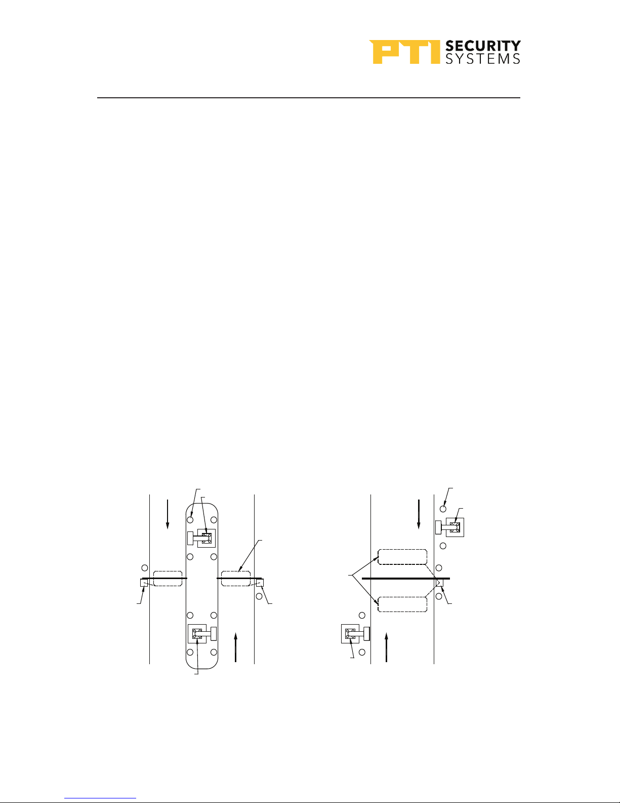
Drawing 1: Drive up accessability
Inside of propertyInside of property
BOLLARD
EXIT KEYPAD
DETECTOR
LOOP
DETECTOR
LOOPS
BARRIER
OR PAD
BARRIER
OR PAD
ENTRY KEYPAD
ENTRY KEYPAD
Outside of property Outside of property
SLIDE GATE
OR PAD

VP Keypad Access Device
3
rev. 7-2017 114A3868.E
Drive Up Accessibility
When the VP will be positioned for drive up accessibility, the device
must be mounted within easy reach of the driver of an automobile
or light truck. Most of these locations use gooseneck stands on an
island between the entry and exit gates (or to the left side of the
gate if a single gate is used). “Drawing 1: Drive up accessability”
on page 2 shows different entry layouts.
Local building codes may set a minimum and maximum height for
devices that are accessible by vehicle. shows suitable mounting
locations when used for vehicle access.
Walk Up Accessibility
When the VP is used for walk up access, it can be mounted on a
stand or attached to a wall. It can also be surface mounted so that
it protrudes from the wall.
Mounting Access Devices
The proper mounting height for the VP varies with the application
and it can be installed at an entrance on a gooseneck/bollard or
attached to a wall.
Once the keypad location is determined, note , the location and
purpose of the device on a site security wiring plan. Keep the plan
in a safe location for future maintenance and service purposes.
Surface Mount
• Surface mounted keypads are often used in conjunction with
door strikes and elevators.
• Mounting height is usually 48” – 58” from the floor to the center
of the ‘5’ button on the touchpad. However, the final location
of the keypad may be affected by local building codes.
• The choice of fasteners depends on the construction material
of the wall.

VP Keypad Access Device
4114A3868.E rev. 7-2017
If the VP is installed on an exterior wall, seal the contact point
between the housing and the wall with a silicone sealant rated
for outdoor use. This prevents moisture and insects from getting
into the housing.
Gooseneck Stand Mount
A gooseneck is commonly used for driveways for vehicle access.
The gooseneck can also be used near doors for wheelchair access
or when sidewalks and landscaping require a freestanding keypad
mount away from the building.
• The base plate of a gooseneck has a hole that accepts conduit
(¾” maximum) for electrical wiring. Ensure the conduit is
placed properly and the wiring runs through the conduit before
mounting the gooseneck stand to the concrete base. The final
location of the gooseneck and the mounting techniques may
be affected by local building codes.
• As a precaution, the gooseneck should be protected with
concrete bollards to prevent vehicles from damaging the
electronics.
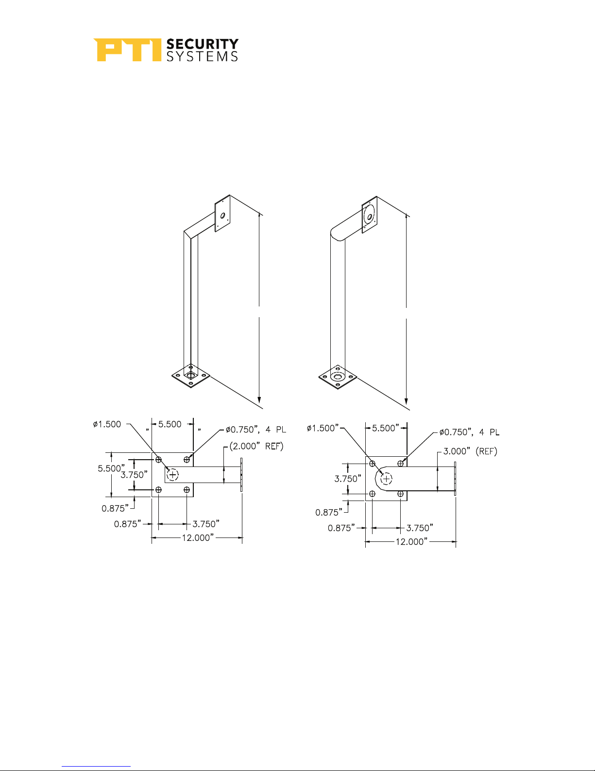
• There are several different styles of gooseneck stands available.
See for the dimensions of two common styles in “Drawing 3:
Gooseneck stand mount” on page 5.
Wall Mount Gooseneck
A wall mount gooseneck allows the
keypad to be mounted on a wall. It may
be used for door strikes or for gates in
driveways ajacent to a building wall, as
shown in “Drawing 6: Silicone seal for
gooseneck” on page 9.
The wallmount gooseneck also gives
wheelchair users access to a device.
Mounting height is generally 48” – 58” Drawing 2: Wall mount
Gooseneck
VP Keypad Access Device
5
rev. 7-2017 114A3868.E
from finished floor to the ‘5’ button on the touchpad for walk-up
access and 45 inches from driveway level to the ‘5’ button on the
touchpad for vehicular access.
If the VP is installed on an exterior wall, seal the contact point
between the housing and the wall with a silicone sealant rated for
outdoor use. This prevents moisture and insects from getting into
the housing.
Drawing 3: Gooseneck stand mount
46.00”
46.00”
VP Keypad Access Device
6114A3868.E rev. 7-2017
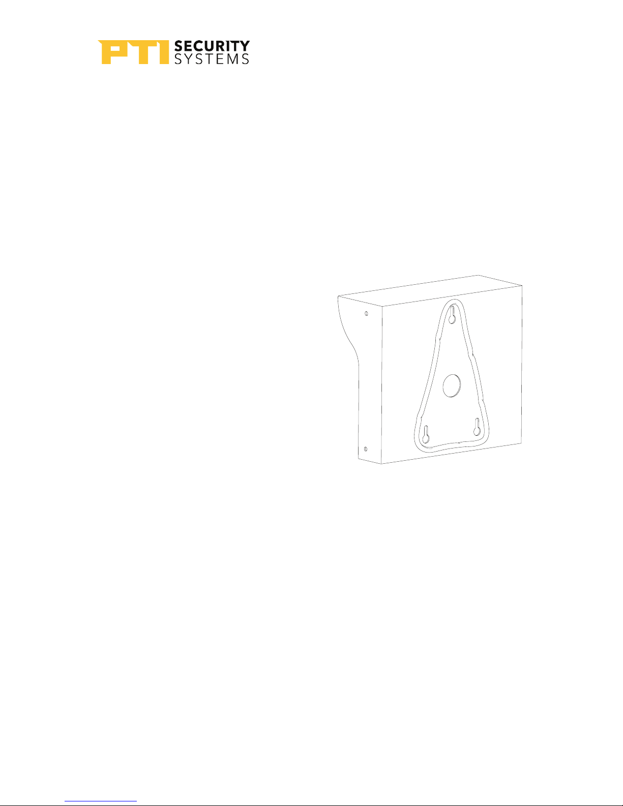
Keypad Adapter Plate
• A keypad adapter plate is an aluminum plate used to mount
keypads to stands, bollards, and goosenecks manufactured by
other companies.
• The installer measures, marks, and drills holes in the adapter
plate to match the stand configuration. To prevent tampering,
ensure the holes are countersunk on the same side as the
installed screws so that the keypad covers the mounting screws.
• The screws and screwholes provided on the aluminum plate
match up with the VP keyhole mounting pattern.
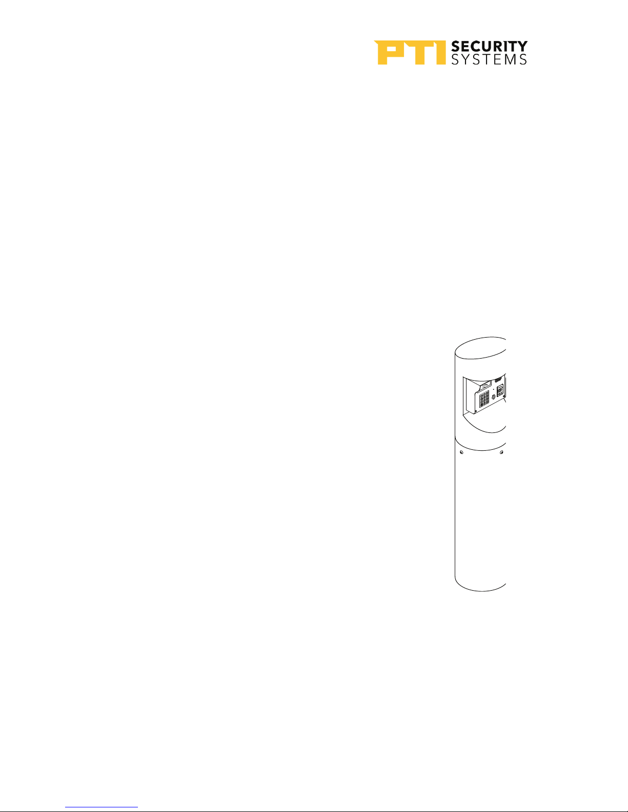
Single Bollard
A bollard is an attractive and functional stand for
keypads. It helps protect the keypad from vehicle
damage. It can be used in driveways for vehicle
access or near doors as a keypad stand. Height is
determined by the length of the pipe on which it
is mounted.
Bollards can be filled with concrete and used as
barriers to protect keypads, walls, or gates.
Both single and double bollards are mounted on
a Schedule 40 10 3/4” diameter pipe with a .365”
wall. This pipe is footed in concrete and filled 3/4
of the way with concrete to create a solid barrier.
The entire pipe and bollard are then painted to
match the facility. Contact PTI Security Systems for
full measured installation plans and instructions.
Drawing 4: single
bollard

VP Keypad Access Device
7
rev. 7-2017 114A3868.E
Installing VP Series Keypads
Power and data communication wiring are the most important
wiring component for VP devices. A VP requires power and
communication lines connected to the controller.
The system will not operate properly if the voltage is below
12VDC.Extreme care should be taken when choosing a power
supply voltage and current rating. Long distance runs may require
a remote power supply to be installed in line with an RB5 relay to
ensure proper operation
PTI recommends that power and data communication be run
through a single 18 AWG, 4-conductor shielded cable. Some
installations will require larger gauge wire. See “Drawing 5: Wiring
for VP keypad” on page 8 for details on connecting the wiring
to the VP device.
Additional cables may be needed for the intercom, gate operator,
door strike, presence detector, or other device.
• Use approved electrical conduit to supply the wiring to the VP.
• Local building codes determine the actual installation
techniques and wiring methods.
• Only licensed contractors should install VP devices.
• Correct installation methods are critical for a trouble-free
keypad. Most of the problems that emerge during use can be
traced back to poor installation techniques or improper wiring.
All installations must conform to local building and electrical
codes. When discrepancies exist between local codes and this
manual, local code takes precedence.
With the RS485 communication scheme, a keypad can be located
as far as 4000 feet from the controller, therefore shielded twisted
pair cable with ground wire is required for optimal operation.
Additionally, larger gauge wire must be used the farther the
device is from the controller.
VP Keypad Access Device
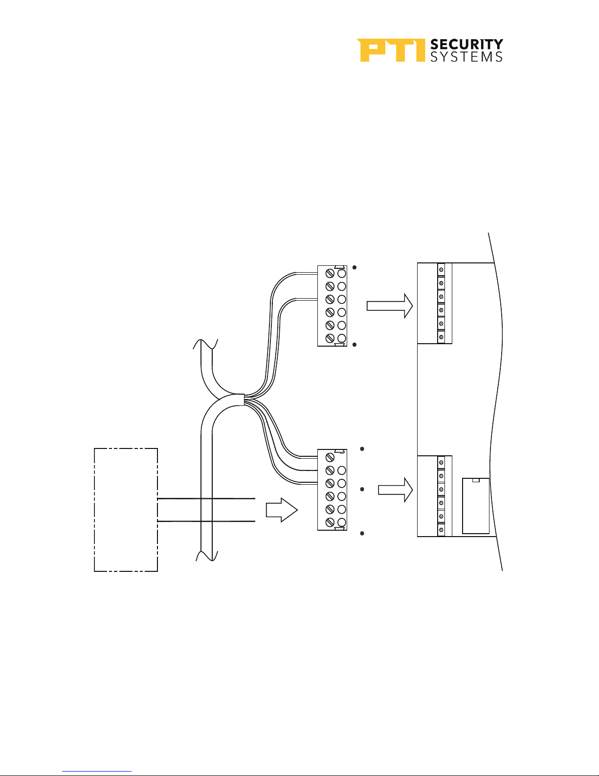
8114A3868.E rev. 7-2017
FROM
CONTROLLER
DATA
GATE
OPERATOR/
DOOR STRIKE
POWER
(DC POWER
CONNECTION
SHOWN)
RELAY
Refer to gate operator or door strike
manufacturer installation instructions
for proper wiring to keypad relay
Power & data from
power supply and
controller
Power & data to
other AI devices
GRN
WHT
SHLD
4 65321
RED
BLK
65321 4
P1
K1
P2
AC/
DC+
D+
NC
COM
NO
GND
D–
AC
GND
GND
DC–
DC–
Drawing 5: Wiring for VP
keypad
VP Keypad Access Device
9
rev. 7-2017 114A3868.E
Installation Instructions
1
Open the device by removing the four stainless steel button
head machine screws on the side of the keypad case using the
security hex key provided with the unit. The front and back half
will separate.
2
Mount the back plate to the desired keypad location using the
three-keyed holes. Seal around the back of each screw hole
and around the back of the wire hole with an outdoor silicone
sealant as shown in
3
If the keypad is being mounted
on a gooseneck or bollard, run
a bead of silicone in a triangle
around the three screw holes
as shown in Drawing 6 on page
9:
If the keypad is being mounted
on a wall, before mounting, run
a bead of silicone in a square
around the back of the keypad
about ½ inch from the edge.
4
Pull the necessary wires through the wire hole on the back
of the housing. Allow an extra 1 foot of wire to remain inside
the housing. After the wire connections are complete, excess
wire can be pushed back into the gooseneck or wall or it
can be carefully positioned inside the keypad housing for
future maintenance and service. Each keypad should have
the following wires as shown in “Drawing 7: Wires for the VP
keypad” on page 10:
Drawing 6: Silicone seal for
gooseneck

10 114A3868.E rev. 7-2017
-One of 18 AWG, 4-conductor, shielded cable coming in
from the controller or from the previous AI device in line.
-One of 18 AWG, 4-conductor, shielded cable going out to
the next AI device in line (if there is another AI device down
the line).
-One of earth ground wire
-One or two 2 of 18 AWG, 2-conductor cable(s) coming from
the gate operator or door strike.*
* A cable for the door strike or gate operator will only be present if the relay inside the
specific keypad is used to trigger the door or gate. The controller can be configured to
trigger a gate or door using relays on the circuit board, a separate relay board, or almost
any other AI device.
For security reasons, the relay in the keypad used to gain access to the secured area
should not be used to allow access to the area. Relays which allow access to secured areas
should be in the secured area
8-32 x 3/8" Screws
(qty 3)
Cover hole
with silicone
RG 59U Camera Cable
(If optional camera is part
of this device)
18GA, 2-Conductor Unshielded Cable
(only if relay in this device used to
trigger Gate/Door Strike)
18GA, 2-Conductor Shielded Cable
(for Intercom)
18GA, 4-Conductor Shielded Cable
(RS485, may have more than one
cable to daisy-chain to other
Access interface devices
Earth Ground
(connect to Chassis Ground
with wire nut and tape)
Chassis Ground
(connect to Earth Ground
with wire nut and tape)
Chassis Ground
(connected to keypad)
Drawing 7: Wires
for the VP keypad

VP Keypad Access Device
11
rev. 7-2017 114A3868.E
-One of 18 AWG, 2-conductor, shielded cable coming from
the intercom base station if intercoms are being used.
-One of RG59U video cable if a pinhole camera is being
used.
-One of 18 AWG, 2-conductor cable for the presence sensor
if it is being used.
5
Strip back the outer insulation and shield foil from both of
the 18 AWG, 4-conductor, shielded cables (coming from the
controller or previous AI device in line and going out to the
next AI device in line), being careful not to cut the bare shield
wire. Strip ¼ inch of insulation off the end of each of the
individual colored conductor wires.
6
Remove the terminal blocks from the keypad circuit board by
sliding them up and off.
7
For Terminal Block P1 “Drawing 8: Terminal block P1
wiring” on page 1111: Insert both red wires (coming in
from the power supply and going out to the next AI device)
into terminal slot 1 on the first terminal block (P1).
Terminal Block P1 (Left)
1. Red DC +*
2. (see footnote)
3. Black DC -
4.
5. Earth Ground if applicable
6.
* If using AC power, place the AC
wires in slots 1 and 2. We recommend
12-18 VDC, but 12-18 VAC can be used.
Drawing 8: Terminal block P1
wiring
VP Keypad Access Device
12 114A3868.E rev. 7-2017
8
Ensure that both wires are seated all the way inside the slot.
Use a flathead precision screwdriver to tighten down the
terminal screw.
9
Verify that the terminal slot has tightened down on the copper
wire and not on the rubber insulation. There should be no
copper wire showing outside of the terminal slot. Gently tug
the wires to verify that they are tightly held inside the terminal
slot.
10
Insert both black wires into terminal slot 3 on P1. Ensure
that both wires are seated all the way inside the slot.
Repeat this process with each of the remaining wire
connections, placing them as shown in “Drawing 8: Terminal
block P1 wiring” on page 11.
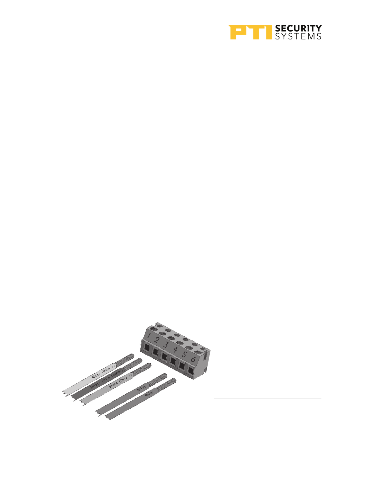
11
For Terminal block P2 “Drawing 9: Terminal block P2
wiring” on page 12. If a gate operator or door strike is
being triggered directly from this keypad,use pins 4, 5, and
6 for the relay and the wires will connect to two of these three
pins.
Terminal Block P2 (Right)
1. White Data +
2. Shield *
3. Green Data -
4. Relay Normally Open Wire
5. Relay Common Wire
* Shield wire should be
insulated with heat shrink
or electrical tape
Drawing 9: Terminal block P2 wiring

VP Keypad Access Device
13
rev. 7-2017 114A3868.E
12
Refer to the gate or door strike manufacturer’s instructions to
determine whether it needs to be connected to the normally
open and common or to the normally closed and common.
An earth ground must be supplied either:
-Through the mounting of the keypad to a conductive
surface with an earth ground.
-Using the earth ground wire and a proper earth ground
connection.
13
The earth ground wire is connected in locations where the
keypad is mounted on a wall that is wood, stone, or other
nonconductive material. It is not always necessary when it is
mounted on a grounded bollard or gooseneck.
14
To connect the ground wire, run a copper wire from a grounded
water pipe or from a copper rod in the ground to the keypad
and connect it to the green earth ground wire using a wire nut.
In this case, Jumper J1 should be set to ‘Normal’.
15
This installation must meet applicable code as the type of wire,
depth of burial, and size of the rod may vary by municipality
16
Connect any additional features such as an intercom, gate
operator, or pinhole camera. Details are on page 14 to
page 17.
17
After all wiring is complete, gently push the excess wire
back through the hole in the wall or gooseneck, leaving just
enough slack to allow the keypad to be opened for service
or maintenance. Seal the back wire hole with outdoor-rated
silicone sealant and then screw the housing back together.
Loose un-insulated wires (Typically used for earth ground)
cannot be located inside the unit’s case. Make connections for
un-insulated ground wire outside the case.

VP Keypad Access Device
14 114A3868.E rev. 7-2017
Connecting Additional Features
(not on all models)
The VP keypad may have additional features and functions. They
need to be connected after steps 1 - 14.
Intercom
• Connect the wires to terminal block P3 in the upper left
corner of the board as shown in “Drawing 10: Intercom wiring
and jumper configuration” on page 15. The connection and
jumper settings will vary depending on whether the intercom
is LEF Single Master Station, LEF Multiple Master Station, or
NEM type intercom. Refer to the manufacturer’s instructions.
The VP with Intercom can be connected to an Aiphone LEF or
Aiphone NEM intercom.
• The intercom wiring must be separate from all other wiring to
either keypad. Use 18 AWG, 2 or 3-conductor shielded cables
for the intercom depending on the type of intercom being
used. Refer to the Aiphone specifications for more detail.
• The intercom type jumpers on either keypad circuit board must
be set to match the type of intercom that you are using, so
reference the configuration table in Drawing 10 on page 15.

15rev. 7-2017 114A3868.E
INTERCOM TYPE VP JUMPER CONFIGURATION
INTERCOM JUMPER
CONFIGURATION TABLE
LEF (SINGLE
MASTER STATION)
LEF (ALL BUT
SINGLE MASTER
STATION)
NEM (ALL)
NEM
LEF
NEM
LEF
LEF Single
All Others
J3
J4 J5
NEM
LEF
NEM
LEF
LEF Single
All Others
J3
J4 J5
NEM
LEF
NEM
LEF
LEF Single
All Others
J3
J4 J5
SEE INTERCOM JUMPER
CONFIGURATION TABLE FOR
PROPER JUMPER PLACEMENT
LEF SINGLE-MASTER STATION
AND ALL NEM INTERCOM
TYPES WIRING
LEF MULTI-MASTER
STATION WIRING
- OR -
TO
OFFICE
TO
OFFICE
TO SPEAKER AND
CALL BUTTON
(ONLY ON KEYPAD W/
INTERCOM ONLY)
RED
BLK
1
E
–
RED
BLK
GRN
1
E
–
1
E
–
P3
NEM
LEF
NEM
LEF
J4
J5
LEF single
All others
J3
P4
SW
SW
SPKR
SPKR
PROGRAM
SW1
Drawing 10: Intercom wiring and
jumper configuration

VP Keypad Access Device
16 114A3868.E rev. 7-2017
Gate Operators
• Most electric gate operators require a ‘normally open’
contact (pins 4 & 5). Some electric door strikes require a
‘normally closed’ contact (pins 5 & 6).
• If door strikes are used it is recommended that they be 12V DC.
• Install a shunting diode across the solenoid to prevent ground
spikes from disrupting the keypad communication.
• The VP has a presence sensor function that allows the keypad
to be connected to a loop detector, or pressure mat requiring
a ‘presence’ in order to use the keypad. This function prevent
users from walking to, and using, the keypad in a driveway area
where they may be in danger from vehicles or the gate.
• This function is often used in connection with a gate operator
and loop detector. Loop detector output wires are connected
to terminal block P7 in the keypad. The keypad is then
programmed with the Presence Required ‘ON’. see
‘Setup Functions’ on page 24 for information on setting up
this feature.
• Do not connect a gate operator or door strike to a keypad
located directly outside the area it secures. This improves
security by preventing someone from vandalizing the keypad
to gain access to your site.
Do not place a diode across AC strikes as it will short out the
power supply for the strike.
Check the voltage level!
Relay voltage must not exceed 30 volts.
Wiring the relay to the operating device introduces the
operating device control voltage into the keypad housing.
The VP is not designed for the presence of
high voltage inside the keypad case.
Table of contents


