PTM ADVANCE SUPER USB User manual


2
Dear customer, thank you for buying this PTM product.
We advise you to read this manual carefully
in order to use the product at best.
SAFETY AND MAINTAINANCE INFORMATION
Never open the protection box of the scale.
Should the scale be damaged, or should liquids have soave in, have the scale checked by a service point.
Never pull the cables in order to disconnect the scale, but unscrew the connectors in the right way.
If the device is provided with an electro-valve control box, remind that this is equipped with a fuse for
protection against power supply inversions and current overflowing. In case the fuse breaks down, replace it
with an equivalent one.
Do not lay the device cables (e.g. load cell cables, data transmission cables, cables to control relay boards,
etc.) near supply cables of other electric or electronic devices.
Supply the device with tensions consistent with the technical features of the product.
Have installation and maintenance work carried out by qualified staff.
Working on the electro-valve control box, by making connections or adjustments which are not authorized by
PTM, is prohibited.
Do not lay the cables which are connected to the scale near moving mechanical parts.
Once you have finished working with the device, we suggest you store it on its holder.
Before cleaning the machine with high-pressure water, protect the scale against possible water infiltrations.
We also remind you to be extremely careful and not expose electronics, cables and other optionals to direct
water jets.
It is possible to clean the scale outside by using a soft and damp cloth, avoiding solvent or abrasive
substances, sharp or cutting objects which can damage the device.
Do not expose the scale to temperatures higher than the limits indicated in the technical features.
In order to reach a longer duration, do not expose the scale directly to atmospheric events, such as rain,
snow, frost, etc.
Never unscrew the grounding clamp which can be found on the protection box of the scale.
Do not use sharp or cutting tools to press the keys.
In case of installation, maintenance and reparation of the scale or the load cells, carry out a weight check /
calibration before making the weighing system operating.
Should the scale be equipped with data saving through USB Pen Drive or Memory Card, insert the saving
device in the correct way.
Before carrying out installation, maintenance and reparation works on the scale or the load cells, disconnect
all the machines which could be connected to the weighing system.
Before carrying out installation, maintenance and reparation works on the system, disconnect the power
supply.
Should the scale be equipped with relay boards, never connect the board directly to electric engines, devices
with a higher tension than 110V, etc.
During the charge of the machine battery, disconnect the power supply cable from the scale.
Before carrying out welding on the machine, disconnect all the cables from the scale.
In case of welding on the machine, place the grounding clip near the welding point, in order to prevent
electric current from passing through the load cells.
In case of welding on the device/machine, disconnect the electro-valve control box and the electronic
equipment, by unplugging the power supply cable, all the electro-valve cables and the connection cable to
the handheld remote control.
We suggest NOT to use electro-valves which have the connection to the body of the electro-valve itself.
All responsibility for installation, maintenance and reparation works falls on the person who carried them out.

3
The constructor of the machine on which the device is installed takes on the responsibility to fix the parts of
the device properly, in order to prevent any dangerous contact of the operator with the dangerous area. In
particular, if the device can control electro-valves, when the operator pushes a button, he is supposed to be
aware of the corresponding movement on the machine.
It is responsibility of the constructor of the machine on which the device is installed to:
oEvaluate risks and safety of the system
oProvide the correct power supply on the device, in order to guarantee the correct functioning of the
device in full respect of the regulation EN 60204-1.
oIf the device controls electro-valves directly, supply the symbols of the controls that you find on the
device, so that they are conformed to the directive.
oCorrectly describe the functioning of the different keys and of the valves associated, so that the
machine on which the device is installed can work in the correct way.
Any change and/or alteration on the hardware or software made on the product, on the device or on the
security systems of the product, if not expressly authorized by PTM S.r.l., makes any responsibility of the
constructor concerning "CE" conformity drop.
ATTENTION!
Do not use high-pressure devices to clean the weighing scale and the load cells.
PTM s.r.l. declines any responsibility in case the regulations above are not observed, and invites the
operator to the correct use of the device.

4
INDEX
FUNCTIONS AND FEATURES....................................................................................................................................5
TECHNICAL FEATURES.............................................................................................................................................7
OPTIONALS.................................................................................................................................................................7
WEIGHING SCALE STRUCTURE...............................................................................................................................8
KEYS FUNCTIONS......................................................................................................................................................9
TO START..................................................................................................................................................................10
MULTIPLE CHANGE OF A PARAMETER................................................................................................................14
HELP ..........................................................................................................................................................................15
ENTRY OF TEXT AND NUMBERS ...........................................................................................................................16
COMMUCATION WITH SOFTWARES......................................................................................................................17
MENU .........................................................................................................................................................................18
MAIN MENU ...............................................................................................................................................................19
SUBMENU..................................................................................................................................................................20
PROGRAMMING........................................................................................................................................................37
RECIPE SELECTION.................................................................................................................................................37
LOADING PROGRAMMING......................................................................................................................................44
UNLOADING PROGRAMMING.................................................................................................................................44
NEW RECIPE.............................................................................................................................................................45
CHANGE RECIPE......................................................................................................................................................50
LOADING OPERATION.............................................................................................................................................55
UNLOADING OPERATION........................................................................................................................................62
CHANGES BLOCK THROUGH PIN CODE ..............................................................................................................66
ACCESS TO THE CODE MENU................................................................................................................................67
CODE LIST.................................................................................................................................................................68
PRINT EXAMPLES ....................................................................................................................................................77
OPTIONALS...............................................................................................................................................................79
CONNECTORS PLAN ...............................................................................................................................................80
TROUBLE SHOOTING ..............................................................................................................................................81
PTM IN THE WORLD.................................................................................................................................................83
DISPOSAL REGULATIONS .....................................................................................................................................84
DECLARATION OF CONFORMITY ..........................................................................................................................84
WARRANTY...............................................................................................................................................................85

5
FUNCTIONS AND FEATURES
The weighing indicators from the series ADVANCE SUPER USB are specific for the management of loading and
unloading operations on Unifeed mixer wagons.
This kind of electronics allows to program and manage up to 150 recipes, with a maximum of 99 components, and
30 components per recipe.
By means of the "PTM Multilink" connecting system, it is possible to connect different optional devices
simultaneously (e.g. printer, weight repeater, remote control, additional relays for Topcut management, mixer, etc.).
The series ADVANCE SUPER USB includes weighing computers with the following features:
Possibility to give a name to components
Memorization of 99 components
Possibility to give a name to groups
Memorization of 100 unloading groups
Possibility to give a name to recipes
Memorization of up to 150 recipes
Possibility to load up to 30 components per recipe
Possibility to unload up to 50 groups per recipe
Total weight screen with the following details: date and time, name of the recipe to load, recipe total, ration
per animal, number of animals
Recipe selection screen with the main details of each recipe: recipe total, ration per animal, number of
animals, mixing time and number of components
Quick selection of the recipe to load
Possibility to manage recipes by selecting the order of the components from a loading list
Management of a numeric keyboard, with the same writing mode of cell phones
Online Help for each screen/function of the scale
Automatic backup of the changes made on components, groups and recipes upon inserting the USB
pendrive
Automatic backup of loading and unloading data upon inserting the USB pendrive
Possibility of digital printing in CSV format, for consumptions and loading and unloading operations.
Overcharge control system
Possibility to prevent the access to some menu, under menu and functions to unskilled and unauthorized
staff (through a PIN code). It is possible to manage to 20 users.
Zeroing through external input or keyboard
Loading break through external input or keyboard
Loading stop through external input or keyboard (optional)
Simultaneous connection of more repeater displays/optionals
Management of the recipe mixing during the loading
Possibility to specify for each component break time and alarm duration after the loading
Possibility to specify for each group the alarm duration after the unloading
Possibility to manage international measurement units
Available weight divisions: 1-2-5-10-20
Calibration through load cells data
Calibration through load cells chart
Calibration with sample weight
Possibility to set out a threshold for manual dosage
Connection of PTM Multilink peripheral devices
Possibility to use additional I/O modules
Control on possible programming conflict between outputs
Self-detection of the number of relay boards connected
Connection to the printer (by request)
Possibility to set out the automatic unloading
Management of component consumptions

6
Proportional recalculation of the quantities of the recipe components in case of rest from the previous
unloading (it can be enabled/disabled for each single recipe)
Proportional recalculation of the quantities of the recipe components in case of overload of the first
component (it can be enabled/disabled for each single recipe)
Proportional recalculation of the unloading quantities in case of overload (it can be enabled/disabled for each
single recipe)
Management of the automatic load of the components from SILO (option)
Management of the MAINTENANCES of MIXER WAGON (option)
Contrast adjustment
Brightness adjustment
Integrated clock
Detection of supply tension
Multilanguage
Possibility to show the weight in reverse mode
Backup of the changes made on components, groups and recipes, made on the weighing computer
Backup of the last 800 loadings and unloadings carried out by the weighing computer
Backup of the settings and calibration of the weighing computer

7
TECHNICAL FEATURES
High sensitivity membrane keyboard
Cast aluminium casing
Protection class: IP 68 with plug-in connectors
Size: L 258 X H 212 X P 75 mm
Weight: 2000 gram ca.
Display: LCD backlit Black/White 320x240 pixel/dot (5.7") with 16 grey levels
Display visible in full sunlight
Memory: Eeprom non volatile
Clock / Calendar
Available weight divisions: Kg. 1 –2 –5 –10 –20
Resolution: 135.000 dd
Operating conditions: - 30 + 70 C°
Relative humidity: 95 %
Power supply: from 10 to 32 V dc
Absorbed power: 4 VA max
Load cells in parallel connection: Max 12 (350 Ω)
Load cell power supply: 5 Vcc
Margin of reading error: +/- Kg. 1 out of Kg. 10.000
Display data field: +99999 ; -99999
Measuring range: ± 2 mV; ± 20 mV
Conversion speed per second: 10 / sec.
No. of RS232 serial outputs: 1 fixed; 2 optional
Consumption: 12V –ca 250 mA (in case of 4 connected load cells)
Protection against radiofrequency interferences
Elimination of power supply interferences
Signalling of low tension
OPTIONALS
Repeater Displays: MV6, AV20-5, Big Display, AV40-5
Portable Displays: AV50/AV80
Multilink TR60: RF Antenna for portable Display AV50/AV60/AV65/AV80
Multilink TR61: RF Antenna (automatic load of the components)
4in-12out Board: Board 4 inputs 12 outputs (automatic load of the components)
16out Boards: Board 16 outputs (automatic load of the components)
Multilink Drive 8: I/O board
Multilink RF7: RF Antenna for Radio control
Multilink Printer Mod. P255/P256/P260/P261
Multilink Drive 8: I/O board #2
Multilink Drive 8: I/O board #3
Multilink Drive 8: I/O board #4
Inverter
Power supplier

8
WEIGHING SCALE STRUCTURE
1. Identifying plate: In this area of the keyboard there is the identifying plate where the scale model is
indicated.
2. Display LCD 320x240 with 16 grey levels: LCD Graphic display where all information of the weighing
scale are indicated, here all the different steps of the weighing operations are indicated. To make the
access to the end user easier, the scale is equipped with interactive graphic.
3. Numeric Keyboard: Numeric keyboard for the insertion of numbers and letters.
4. Function keys: In this keyboard area there are some function keys, among them there is the tare zeroing
key and the partial weight zeroing key.
5. Shift keys: In this area of the keyboard there are some keys used to shift among the different menus of the
scale.
6. Connctors: There are four connectors for the junction to the power supply, to the load cells, to the
optionals and to the USB pen-drive.
7. Male coupling: Scale fixing support. Together with the weighing kit the female coupling is supplied.
8. Serial Number: Serial Number of the scale. In case of service, please communicate to PTM or to the
authorized dealer this number to allow the product identification.
9. EC Identifying plate: This is the identifying plate of the weighing scale. In case of service, please
communicate to PTM or to the authorized dealer this number to allow the product identification. Please, do
not remove or damage this plate.
5
7
9
6
4
3
2
1
8
9
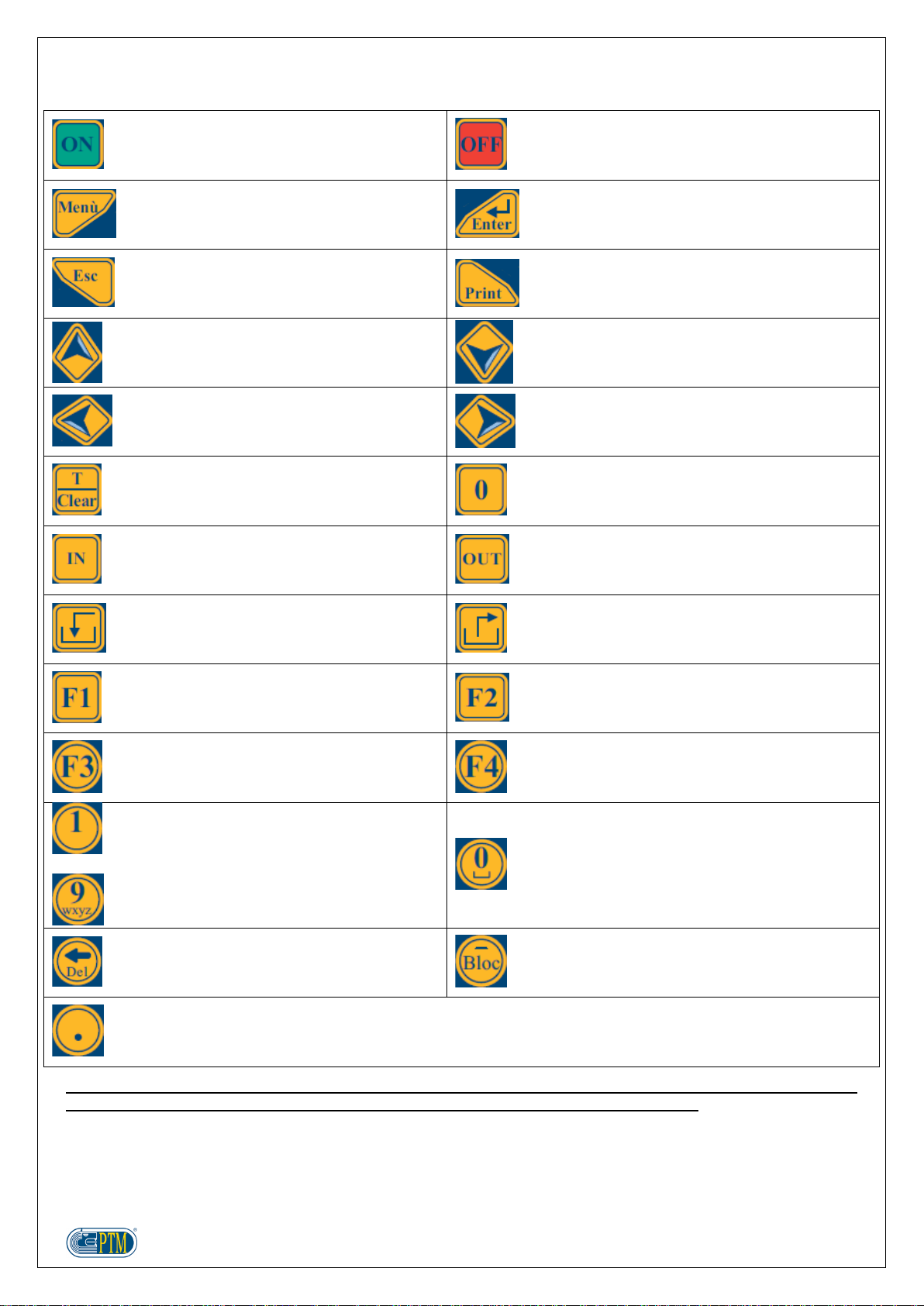
KEYS FUNCTIONS
ON
OFF
ACCESS TO USER MENU
ADVANCED PARAMETERS
ENTER
EXIT
PRINT
SHIFTING THE CURSOR UPWARDS
MOVING TO THE NEXT COMPONENT
MOVING TO THE NEXT GROUP
SHIFTING THE CURSOR DOWNWARDS
MOVING TO THE PREVIOUS COMPONENT
MOVING TO THE PREVIOUS GROUP
SHIFTING THE CURSOR TO THE LEFT
SHIFTING THE CURSOR TO THE RIGHT
TARE ZEROING
TOTAL WEIGHT RECALL
PARTIAL WEIGHT RECALL
PARTIAL WEIGHT ZEROING
RECIPE SELECTION MENU
LOADING PROGRAMMING
RECIPE SELECTION MENU
UNLOADING PROGRAMMING
START OF THE LOADING OF THE SELECTED
RECIPE
START OF THE UNLOADING OF THE SELECTED
RECIPE
ACTIVATION / DEACTIVATION OF THE
TOPCUT FUNCTION (IF AVAILABLE)
VISUALIZATION OF MULTILINK MODULE ALARMS
(IF AVAILABLE)
CHANGE ALL VALUES
CHANGE WRITING MODE (CAPITAL LETTERS,
SMALL LETTERS, NUMBERS)
QUICK SELECTION OF COMPONENTS, GROUPS
AND RECIPES
ENTRY OF NUMBER AND LETTERS BY
MEANS OF THE NUMERIC KEYBOARD
ENTRY OF NUMBER “0” OR SPACE
DELETE CHARACTER (DELETE)
ENTRY OF CHARACTER “-“
BLOCKING/UNBLOCKING DURING LOADING AND
UNLOADING OPERATIONS
ENTRY OF DECIMAL POINT
ONLINE HELP
ATTENTION: According to the menu, some keys may have either additional or different functions. For more
information, please read the online help on the scale, or go on reading this document.

10
TO START
FUNCTION
OPERATION
DISPLAY
The operations descrive below concern the basic functioning of the weighing computer.
For extra information, please go on reading this document.
Switch ON
Press
Switch OFF
Press
TOTAL WEIGHT
After the introduction, the weighing computer shows the screen TOTAL WEIGHT:
1. Current screen (TOTAL WEIGHT or PARTIAL WEIGHT)
2. Current date and time
3. Measurement unit used by the scale
4. Value of total or partial weight detected by the scale
5. Current selected recipe
6. Summary information regarding the current selected recipe: Total weight to load,
ration per animal and total number of animals
7. Icon showing the status of Topcut knives in the mixer wagon (by request)
8. Key to press in order to visualize the online help of the scale
9. Alarms for Multilink modules (by request)
10. USB Pendrive inserted in the weighing computer
11. Software Release installed on the weighing computer
3
2
1
5
7
8
9
10
11
6
4
11
FUNCTION
OPERATION
DISPLAY
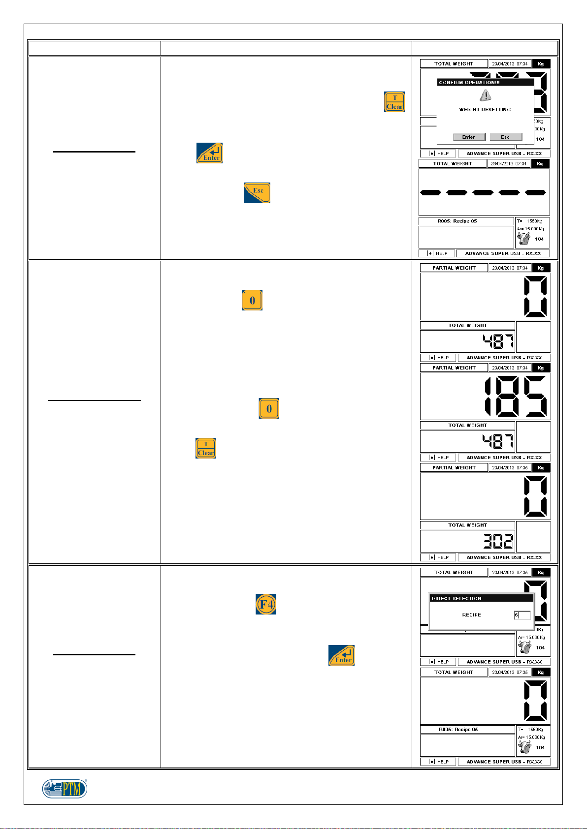
TOTAL WEIGHT
Zeroing the total weight
The screen TOTAL WEIGHT shows the value of total
weight measured by the load cells.
To reset the weight value to zero, keep the key
pressed for 3 seconds, until the confirmation message
appears on the display.
Press to confirm the tare zeroing: the value of
total weight will be reset to zero.
Otherwise, press to cancel the operation.
PARTIAL WEIGHT
Zeroing the partial
weight
It is possible to move from the screen TOTAL
WEIGHT to the screen PARTIAL WEIGHT by
pressing the key .
The value of total weight is displayed in the lower part
of the screen.
When going on with the loading operations, the
display shows the partial weight loaded from that
moment on, while the updated total weight is
displayed in the lower part of the screen.
By pressing the key again, it is possible to reset
the partial weight to zero.
Press to go back to the menu TOTAL WEIGHT.
TOTAL WEIGHT
Direct selection of the
recipe
In order to carry out a DIRECT SELECTION of the
recipe to load, place yourself in the menu TOTAL
WEIGHT and press .
In the superimposed screen it is possible to enter the
number of the recipe to load by means of the numeric
keyboard, and confirm it by pressing .

12
FUNCTION
OPERATION
DISPLAY
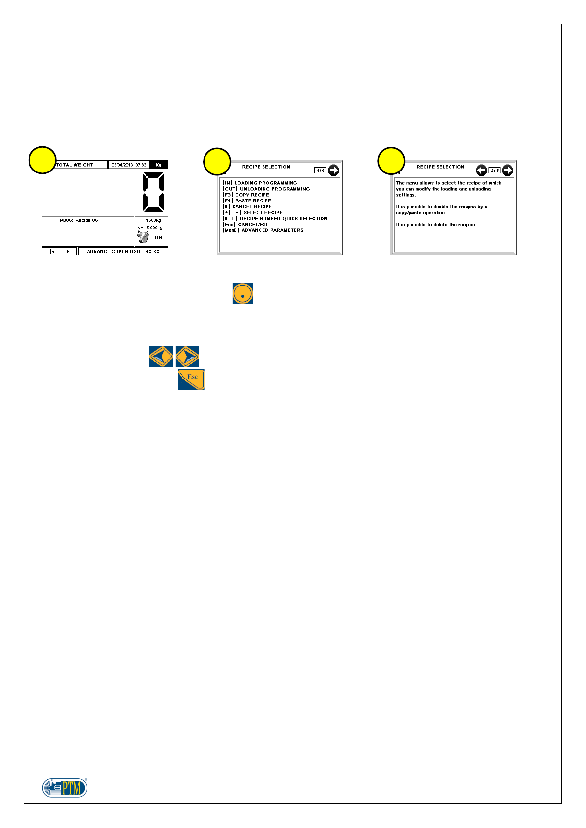
RECIPE SELECTION
In order to enter the menu RECIPE SELECTION
press or .
ATTENTION: for more detailed information, please
see the section PROGRAMMING and RECIPE
SELECTION.
TOTAL WEIGHT
Starting the loading of
the recipe
To start the LOADING of the recipe selected in the
menu TOTAL WEIGHT, press .
Should an empty recipe be selected, the display
shows the error message ERROR!!! Recipe Total
Void!!! It is possible to leave this message by
pressing .
TOTAL WEIGHT
Starting the unloading of
the recipe
To start the UNLOADING of the recipe selected in the
menu TOTAL WEIGHT, press .
Like for the loading, should an empty recipe be
selected, the display shows the error message
ERROR!!! Recipe Total Void!!! It is possible to leave
this message by pressing .
TOTAL WEIGHT
Manual TOPCUT
(by request)
If the scale is arranged for the TOPCUT function
(control of knives for grinding the material in the mixer
wagon), the icon showing the status of the knives
appears in the menus TOTAL WEIGHT and PARTIAL
WEIGHT.
It is possible to enable/disable MANUAL TOPCUT
only from the menus TOTAL WEIGHT and PARTIAL
WEIGHT.
It is not possible to leave the menus TOTAL WEIGHT
and PARTIAL WEIGHT as long as the function
MANUAL TOPCUT is not disabled.
For more details, please read the specific section in
the next pages.

13
FUNCTION
OPERATION
DISPLAY
TOTAL WEIGHT
Manual TOPCUT
(by request)
Static
Recipe times
Dedicated times
This mode can be set out in the sub menu MANUAL
TOPCUT, where it is possible to choose among the
following functioning modes:
STATIC
RECIPE TIMES: with the same Knives IN and
Knives OUT times of the selected recipe
DEDICATED TIMES: with Knives IN and Knives
OUT times independent from the times of the
selected recipe
After choosing one of the three available modes, it is
possible to enable it by pressing the key in the
screens TOTAL WEIGHT and PARTIAL WEIGHT.
The word MAN or AUTO appears above the TOPCUT
icon, according to the functioning mode selected.
In the STATIC mode, the TOPCUT icon shows the
word MAN and the knives are activated (IN) and
deactivated (OUT) upon enabling/disabling the mode.
In the modes RECIPE TIMES or DEDICATED TIMES,
the TOPCUT icon shows the word AUTO and the
knives are activated (IN) and deactivated (OUT)
according to the times set out in the submenu
MANUAL TOPCUT.
These modes can be disabled by pressing ; in
this case the word OFF appears above the icon
TOPCUT.
TOTAL WEIGHT
MULTILINK
(by request)
Module alarms
In case the weighing computer is connected to any
Multilink modules, and there communication problems
with the scale, the icon is displayed in the
screen TOTAL WEIGHT.
By pressing it is possible to visualize the scrren
ENABLED ALARMS, with the list of Multilink modules
having communication problems with the scale; in this
way it is possible to identify the source of the fault
immediately.
To leave, press .

14
MULTIPLE CHANGE OF A PARAMETER
In some menus and for some parameters, it is possible to make a single change to set out a value for all the
associated positions in the menu.
For instance, in the menu LOADING PROGRAMMING it is possible to modify the value LOADING ALARM % for
all the components of the recipe, by entering the value 20% only once, instead of entering it for each component.
It is possible to enable the multiple change with single entry as follows:
1. press
2. in the screen MODIFY ALL VALUES use the numeric keyboard to enter the value you want to give the
parameter for all the elements in the menu
3. confirm by pressing , or cancel by pressing
In the explanation of the next sections the following description will be indicated, every time it is possible to carry
out the multiple change of the parameter with single entry:
With multiple change of the parameter
1
3
2
15
HELP
The weighing computer Advance contains some screens to help the user better understand:
the functions of the keys
the functioning, the settings and the options.
The Help screens are contextual, and contain descriptions concerning the menu which the user is visualizing.
1. The function HELP is available in the menus showing the sign “|.| HELP” at the bottom on the left. In order
to visualize the HELP pages, press .
2. The keys, as well as their function in the menu, are described in the first page.
3. The next pages describe the functioning of the menu, the settings and the options which can be set out.
To scroll the pages, use .
To leave the online help, press .
1
2
3

16
ENTRY OF TEXT AND NUMBERS
It is possible to enter text and numbers by means of the numeric keyboard.
By repeatedly pressing the keys, it is possible to enter other characters than the ones present on the keyboard.
In some menus it is possible to change the writing mode by pressing :
Capital letters ABC (123)
Small letters abc (123)
Numbers 123
In the following you'll find the character corresponding to the number of pressures of the key in CAPITAL
KEY
x1
x2
x3
x4
x5
x6
x7
x8
x9
x10
x11
x12
.
,
?
!
1
A
B
C
Ä
Á
À
Â
Ã
Ç
2
D
E
F
Ë
É
È
Ê
3
G
H
I
Ï
Í
Ì
Î
4
J
K
L
5
M
N
O
Ö
Ñ
Ó
Ò
Ô
Õ
6
P
Q
R
S
Š
7
T
U
V
Ü
Ú
Ù
Û
8
W
X
Y
Z
Ÿ
Ý
Æ
Œ
Ø
Å
Ž
9
and SMALL mode:
KEY
x1
x2
x3
x4
x5
x6
x7
x8
x9
x10
x11
.
,
?
!
1
a
b
c
ä
á
à
â
ã
ç
2
d
e
f
ë
é
è
ê
3
g
h
i
ï
í
ì
î
4
j
k
l
5
m
n
o
ö
ñ
ó
ò
ô
õ
ð
6
p
q
r
s
š
ß
7
t
u
v
ü
ú
ù
û
8
w
x
y
z
ÿ
ý
æ
œ
ø
å
9

17
COMMUCATION WITH SOFTWARES
The weighing computer Advance Super USB can work with the software SUPER DATA MIX or PTM
MANAGEMENT, which allows the exchange of programmings and loading and unloading data, the best
management of the quantities of material, and the control on the operator's work on the wagon.
Here under you'll find some useful advice to communicate with the program.
In order to communicate with the program, it is necessary to get a USB pendrive (supplied as standard
equipment with the scale), and get in the total weight menu.
In order to download data from the program into the weighing computer, get in the total weight menu and
put the USB pendrive in the specific connector.
In order to export loading and unloading data, as well as changes made on groups and recipes, get in the
total weight menu and put the USB pendrive in the specific connector.
Check that the USB pendrive has been put in the weighing computer in the right way.
Do not switch off the weighing computer while sending/receiving data.
Here is the detailed procedure for sending/receiving data:
Create the programmings with the software Super Data Mix or PTM Management
Send the programmings from the software Super Data Mix or PTM Management to the weighing computer
by inserting the USB pendrive in the specific connector.
Get in the total weight menu and insert the USB pendrive.
Wait for the data to be automatically downloaded.
Take out the USB pendrive and carry out the loading/unloading operations.
On the weighing computer it is possible to create or modify components, groups and recipes; all changes
will be then exported to the USB pendrive and imported into the program Super Data Mix or PTM
Management.
Wait for the data to be automatically downloaded upon putting the USB pendrive in the specific connector.
ATTENTION: if the communication between scale and software fails, and data go lost, they can be retrieved as
backup data from the internal memory of the scale (see BACKUP USB).

18
MENU
It is possible to access the following screens:
TOTAL WEIGHT
PARTIAL WEIGHT
MENU
SUBMENU
RECIPE SELECTION
LOADING PROGRAMMING
UNLOADING PROGRAMMING
according to the following scheme:

19
MAIN MENU
FUNCTION
OPERATION
DISPLAY
MAIN MENU
In the MENU you'll find the list of the submenus which
can be selected, in order to access some of the
functions of the scale.
You can access this screen from the TOTAL WEIGHT
by pressing .
MAIN MENU
Submenu
Use the keys to move the cell between the
submenus:
COMPONENTS
GROUPS
COMPONENTS CONSUMPTIONS
RECALCULATION ACTIVATION
SILO (Option)
MAINTENANCES (Option)
MANUAL TOPCUT (by request)
PRINT TO USB (enabling through code)
CONTRAST
BACKLIGHT
WATCH
BATTERY
LANGUAGE
WEIGHT IN REVERSE
USB BACKUP
BACKUP USB PARAMETERS
By pressing it is possible to access the
underlined submenu.
By pressing it is possible to go back to the
menu TOTAL WEIGHT.
MAIN MENU
Shifting the cursor
In the following screens:
MENU
SUBMENU
RECIPE SELECTION
LOADING PROGRAMMING
UNLOADING PROGRAMMING
it is possible to shift the cell:
to the left
to the right
upwards
downwards
20
SUBMENU
FUNCTION
OPERATION
DISPLAY
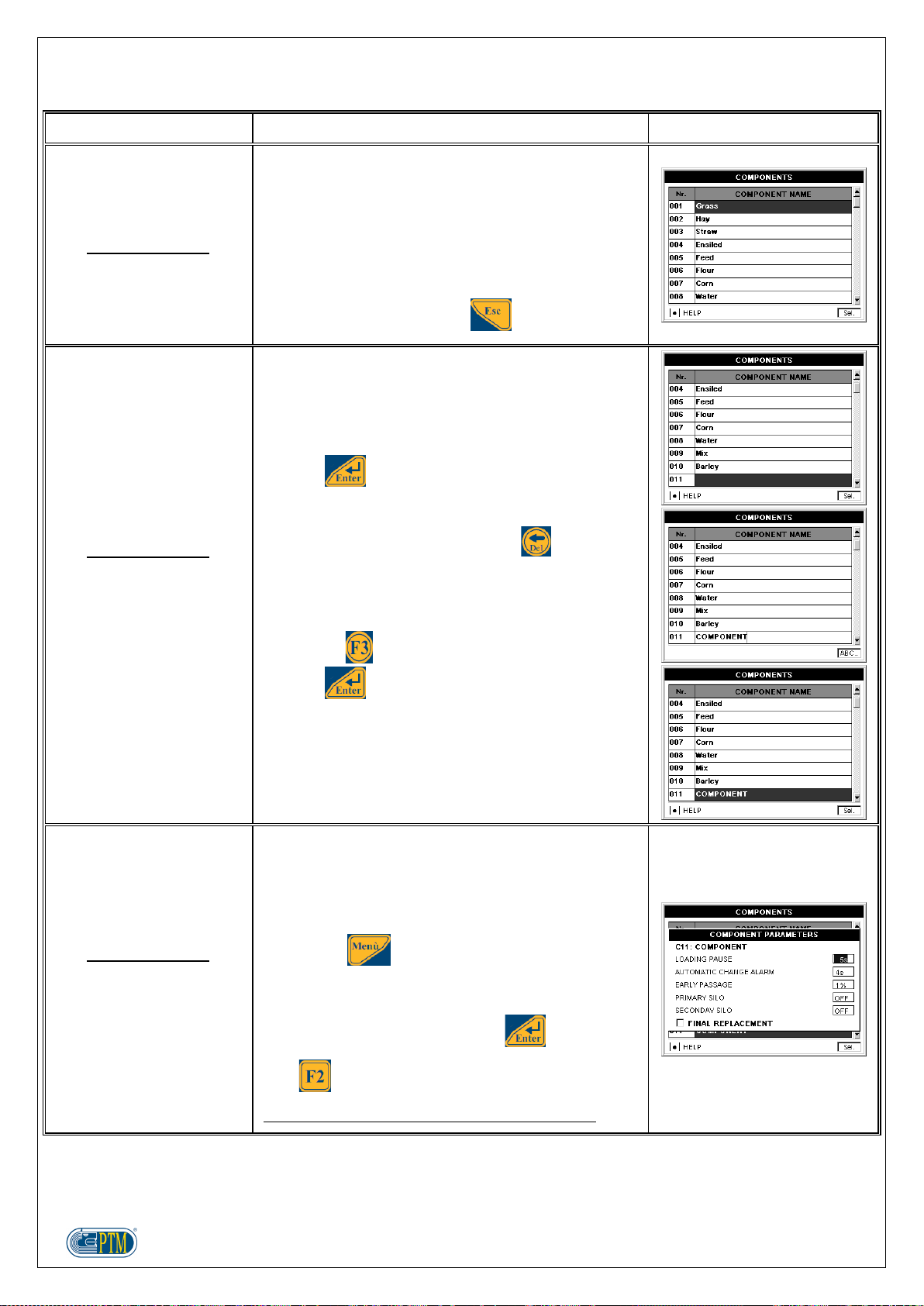
COMPONENTS
The submenu COMPONENTS allows to manage
components, which will be used in the loading
operations of the single recipes.
The names of the components can be entered by
means of programmings with the softwares SUPER
DATA MIX or PTM MANAGEMENT, or on the
weighing computer directly.
To leave this submenu, press .
COMPONENTS
Modify
Create
Erase
It is possible to modify, create or erase a component
as follows:
place the cell in the column COMPONENT NAME,
on the line of the component to create, change or
erase
press
in order to create a new component, it is necessary
to select an empty line
make the wished changes: press , if you wish
to cancel the component; use the numeric
keyboard to change the name (or create it, if the
selected component is new). While modifying the
name, it is possible to change the writing mode by
pressing
press to confirm the changes
COMPONENTS
COMPONENT PARAMETERS
Loading pause
For each component it is possible to set out a break at
the end of the component loading, that is a waiting
time counted down at the end of the component
loading.
Access to the screen COMPONENT PARAMETERS
by pressing .
In the superimposed window it is possible to enter the
value for LOADING PAUSE by means of the numeric
keyboard, and confirm by pressing .
With multiple change of the parameter.
It is possible to enter values between 0 and 999.
Table of contents
Other PTM Accessories manuals

Popular Accessories manuals by other brands

B&C Speakers
B&C Speakers Hf Compression Drivers DE 45 Specification sheet

UltraLux
UltraLux RFWDB INSTRUCTIONS FOR EXPLOITATION

Foerster
Foerster CIRCOGRAPH DS operating instructions

Wonbo
Wonbo Smart Doorbell A3 owner's manual

Emerson
Emerson Rosemount 214C quick start guide

inventum
inventum HB75 instruction manual


Emmaljunga
Emmaljunga NXT Carrycot Supreme instruction manual

ring
ring Doorbell Pro manual

Silvercrest
Silvercrest 284941 Assembly, operating and safety instructions

Aardvark
Aardvark Direct Pro Q10 owner's manual

BONA SPES
BONA SPES VIKING SP16W Instructions for use

ETC
ETC Echo Dual Tech Ceiling-mount Vacancy Sensor installation guide