Ptotec 3300 Guide


93-530-70 Issue 0 Page 3 of 44 © Protec Fire Detection PLC 2007
Table of Contents
1.0 3300 SYSTEM OVERVIEW ..........................................................................................................5
2.0 IMPORTANT NOTES – PLEASE READ ......................................................................................6
3.0 ITEMS SUPPLIED WITH THE 3300 PANEL................................................................................6
4.0 CABLING REQUIREMENTS ........................................................................................................7
4.1 Detector, Alarm and Auxiliary Wiring .....................................................................................7
4.2 Mains Wiring...........................................................................................................................7
5.0 INSTALLATION PROCEDURE ....................................................................................................8
6.0 TESTING OF CABLING PRIOR TO CONNECTION..................................................................11
7.0 DETECTOR CIRCUIT CONNECTIONS......................................................................................11
8.0 ALARM CIRCUIT CONNECTIONS ............................................................................................12
9.0 AUXILIARY INPUT AND OUTPUT WIRING ..............................................................................13
9.1 Keyswitch Input ....................................................................................................................13
9.2 Remote Alarm Input .............................................................................................................13
9.3 Class Change Input..............................................................................................................13
9.4 Global Fault Output ..............................................................................................................13
9.5 Global Fire Output ................................................................................................................13
10.0 REPEAT PANEL WIRING ..........................................................................................................14
11.0 INTERNAL EXPANSION PORT .................................................................................................15
12.0 COMMISSIONING.......................................................................................................................16
12.1 Connecting the Mains...........................................................................................................16
12.2 Installing and Connecting The Standby Batteries ................................................................17
12.3 Switching On ........................................................................................................................17
13.0 PROGRAMMING OVERVIEW ....................................................................................................18
13.1 Access Levels.......................................................................................................................18
13.2 Zone Programming Choices.................................................................................................19
14.0 PROGRAMMING DETAILS ........................................................................................................20
14.1 PROGRAMMING ZONE DISABLEMENTS................................................................................20
14.2 Programming Alarm Disablements ..................................................................................21
14.3 Programming Zone Delays................................................................................................22
14.4 Programming Zones into Test Mode ................................................................................23
14.5 Programming Coincidence Zones ....................................................................................24
14.6 Programming Non-Latching Zones ..................................................................................25
14.7 Programming Expansion Interface Node Information....................................................26
15.0 OVERRIDING SYSTEM DELAYS ..............................................................................................27
16.0 DISABLING THE FIRE LINK INTERFACE ................................................................................28
17.0 DELAYING FIRE LINK ACTIVATIONS ......................................................................................29
18.0 PSU MONITORING TYPE SET-UP ............................................................................................30
www.acornfiresecurity.com
www.acornfiresecurity.com

93-530-70 Issue 0 Page 4 of 44 © Protec Fire Detection PLC 2007
19.0 PROGRAMMING END OF LINE TYPE ......................................................................................30
20.0 PROGRAMMING PULSING ALARMS.......................................................................................31
21.0 FAULT DIAGNOSIS FEATURES ...............................................................................................31
22.0 3300 SOFTWARE VERSION DISPLAY .....................................................................................32
23.0 DETECTOR ZONE FAULT DETAILS.........................................................................................33
24.0 ALARM FAULT DETAILS ..........................................................................................................34
25.0 SYSTEM FAULT DETAILS.........................................................................................................35
26.0 POWER SUPPLY FAULT DETAILS ..........................................................................................36
27.0 FAULT RECTIFICATION GUIDELINES .....................................................................................37
28.0 3300 TECHNICAL SPECIFICATION ..........................................................................................38
29.0 3300 FEATURES SPECIFICATION ...........................................................................................39
30.0 APPENDIX 1. ACCESSORIES AVAILABLE FOR THE 3300. ..................................................40
31.0 APPENDIX 2. 3300 SPARES LIST.............................................................................................41
32.0 APPENDIX 3. DECIMAL TO BINARY CONVERSION CHART.................................................42
33.0 APPENDIX 4. 3300 MAIN PCB DETAILS..................................................................................43
34.0 APPENDIX 5. 3300 PROGRAMMING QUICK REFERENCE GUIDE .......................................44
www.acornfiresecurity.com
www.acornfiresecurity.com

93-530-70 Issue 0 Page 5 of 44 © Protec Fire Detection PLC 2007
1.0 3300 System Overview
The main features of the Protec 3300 Fire Alarm system are:
•Four and eight detector zone models available.
•Four monitored alarm circuits rated at 150mA each.
•Common negative (allowing three wire operation).
•Manual call point activation can override zone delays.
•Re-sounding of outputs if a zone changes from automatic to manual activation.
•Three auxiliary inputs, Keyswitch, Class Change and Remote Alarm.
•Global Fire and Global Fault clean contact connections.
•Monitored Auxiliary 24V output (Overload Protected, 100mA maximum).
•Programmable capacitive or resistive detector circuit end of line monitoring.
•Extensive range of engineering functions, accessed via a 5 digit code entry or key-switch
activation.
•Delays to zones.
•Disablement of zones.
•Coincidence Operation.
•testing of zones.
•Non-latching zones.
•Disablement of alarm circuits.
•Disablement of fire link output.
•Comprehensive fault diagnosis features.
•Expansion outputs to drive one fire link interface and one eight way zonal mimic interface.
•Repeat panel output to drive up to eight 3300 Repeat Panels, no extra driver board is required.
•All interfaces supported as standard.
•Low quiescent current of 15mA (24V dc supply, mains fail fault, no external equipment).
Note: Due to a policy of continuous improvement Protec Fire Detection PLC reserve the right to alter
the specification without prior notice.
www.acornfiresecurity.com
www.acornfiresecurity.com

93-530-70 Issue 0 Page 6 of 44 © Protec Fire Detection PLC 2007
2.0 Important Notes – PLEASE READ
•THE FIRE ALARM PANEL AND ITS ASSOCIATED CONNECTIONS MUST BE INSTALLED,
COMMISSIONED AND MAINTAINED BY A SUITABLY SKILLED AND COMPETENT PERSON.
•THIS EQUIPMENT MUST BE EARTHED.
•THIS EQUIPMENT IS NOT GUARANTEED UNLESS INSTALLED AND COMMISSIONED IN
ACCORDANCE WITH CURRENT NATIONAL STANDARDS.
•THIS EQUIPMENT HAS BEEN DESIGNED AND MANUFACTURED TO CONFORM WITH
THE REQUIREMENTS OF ALL APPLICABLE EU COUNCIL DIRECTIVES.
•THIS MANUAL MUST BE THOROUGHLY READ AND UNDERSTOOD BEFORE
INSTALLATION AND COMMISSIONING OF THIS EQUIPMENT IS UNDERTAKEN.
3.0 Items Supplied with the 3300 panel
•Installation, commissioning and maintenance manual.
•User manual.
•Mounting template.
•Accessory pack, comprising:
•8 x 100µF/22Ωdetector circuit end of line units (41-804-52)
•4 x 10kΩalarm circuit end of line units (41-800-48)
•1 x red battery lead (41-791-64)
•1 x black battery lead (41-790-63)
•1 x inter-battery connection lead (41-796-44)
•1 x 1A HRC power supply fuse (15-131-35)
•1 x 1.6A battery fuse (15-055-40)
www.acornfiresecurity.com
www.acornfiresecurity.com

93-530-70 Issue 0 Page 7 of 44 © Protec Fire Detection PLC 2007
4.0 Cabling Requirements
4.1 Detector, Alarm and Auxiliary Wiring
All external wiring associated with the system must conform to the current I.E.E Regulations and
cabling must conform to the relevant BS specifications. ECA recommended Cable Separation for
Electromagnetic Compatibility in Buildings must be followed.
To comply with EMC regulations Protec recommends the use of screened cabling throughout the
installation. The screens must be securely connected to the screwed earthing studs provided inside
the 3300 enclosure.
Screened cables that are suitable for wiring are:
MICC (PyroTM), Pirelli FP200TM, FireTuffTM, or any other cable which complies with BS 6387
(categories C, W, Z).
Proper glanding of the cable is vital to the correct performance of the system.
4.2 Mains Wiring
The 3300 requires a mains supply exclusive to the panel that uses fixed three core wiring (between
0.75mm2and 2.5mm2) which is fed from a double pole isolating fused spur, fused at 3A.
Unauthorised operation of the mains supply should not be allowed and the fused spur should be
labelled “FIRE ALARM: DO NOT SWITCH OFF”
www.acornfiresecurity.com
www.acornfiresecurity.com

93-530-70 Issue 0 Page 8 of 44 © Protec Fire Detection PLC 2007
5.0 Installation Procedure
The 3300 fire alarm panel circuit boards are housed in a plastic enclosure. When the front is removed
from the panel the circuit boards and the batteries are fully accessible. The panel can still be
controlled even though the front has been removed.
The panel can be surface or flush mounted.
The panel must be located internally in an area that is not subject to dampness, extremes of
temperature or physical abuse. The environmental limits are given in section 21.0
1) Unpacking
After opening the box remove the installation template and spares pack from the packaging,
leaving the 3300 in the cardboard box for protection.
2) Preparing the Mounting Position
Use the installation template in conjunction with a spirit level to mark out the fixing locations
for the panel. Drill and plug the mounting holes previously marked.
3) Removal of the Door
Remove the 3300 unit from the packaging. Remove the two screw covers from the lower two
corners of the front door and unscrew the two front door fixing screws.
Swing the door upward from the bottom and lift away, see figure 5.0.
Put all removed parts in a safe, dry place.
Figure 5.0 – Removing the door from a 3300.
www.acornfiresecurity.com
www.acornfiresecurity.com

93-530-70 Issue 0 Page 9 of 44 © Protec Fire Detection PLC 2007
4) Removal of the Main PCB.
NOTES ON ANTI-STATIC HANDLING OF THE PCBs
Before handling any of the circuit boards in the 3300 it is vital that any operatives
discharge themselves of any static charge that may have built up on them. This can be
done by momentarily touching a solid earth point (a non-painted part of a radiator, for
example).
Handle the PCBs by their sides and DO NOT touch the electronic components on them.
The PCB should be stored in a clean, dry place away from the place of work. Retain the
PCBs in a cardboard box for safety until they are required.
Disconnect the 3 way connector from the main PCB, taking care not to strain the connector or
the PCB. Leave the connector attached to the Power Supply PCB.
Unscrew and remove the two mounting screws on the main PCB. Carefully slide the Main
PCB upward (stage 1) and lift away from the plastic enclosure (stage 2). See figure 5.1.
Store all screws and PCBs in a safe, dry place.
Figure 5.1 – Removal of the 3300 Main PCB.
.
PCB fixing screw
Stage 1
Stage 2
3 way power
connector
PCB fixing screw
www.acornfiresecurity.com
www.acornfiresecurity.com

93-530-70 Issue 0 Page 10 of 44 © Protec Fire Detection PLC 2007
5) Preparing and Fixing the Panel Back-box
The mains cable entry position should be kept away from other system cabling.
Carefully knock out the required cable entry positions and mount the enclosure at the position
prepared in (2) whilst feeding the cables into the enclosure.
6) Refitting the Main PCB
Note: Before re-fitting the main PCB the mains power connections to the Power Supply
PCB should be connected. See section 12.0.
DO NOT SWITCH MAINS POWER ON AT THIS POINT !!
Route the battery cables through to the battery compartment using the channels provided.
Replace the Main PCB (a reversal of removal), ensuring it is pushed fully down to the bottom
edge of the panel. Secure with the two screws removed previously. Take care not to over
tighten the screws.
Re-connect the three way cable from the Power Supply to the Main PCB, do not use undue
pressure and ensure the cable is clipped into the locking ramp on the PCB header securely.
7) Re-fitting the Door
Replace the plastic door by offering the top of the door up to the groove at the top of the
plastic back-box.
Swing the door down and ensure it pushes fully home into the back-box, without fouling the
rubber keypad or light-guides on the main PCB. See figure 5.3 for details.
Tighten the two screws in the lower two corners of the door, and replace the screw covers.
Figure 5.3 – Refitting the 3300 Door.
www.acornfiresecurity.com
www.acornfiresecurity.com

93-530-70 Issue 0 Page 11 of 44 © Protec Fire Detection PLC 2007
6.0 Testing of Cabling Prior to Connection
Before connecting any external cables to any field device (detectors, sounders, auxiliary inputs or
outputs), or the 3300, tests must be carried out using a 500V dc insulation tester (MeggerTM). The
readings between each cable core, and each core and earth should be greater than 10MΩ.
Important Notes:
•Equipment connected to the cabling during insulation tests could be damaged with the high
voltages used during the test.
•Field devices and the 3300 MUST NOT be connected when high voltage insulation tests are being
performed on the cabling, the cabling must be completely discharged prior to connection to any
field devices or the 3300.
7.0 Detector Circuit Connections
Figure 7.0 shows a typical connection regime for a detector zone on the 3300.
Figure 7.0 Typical 3300 Detector Connection
•Ensure the length of the zone wiring is no more than 500 metres.
•Ensure the resistance of each conductor is no more than 15Ω.
•Ensure the capacitance of the zone wiring is no more than 0.27µF (micro-Farads)
when no end of line capacitor is present.
•The end of line unit (8k2 resistor or 100µF/22Ωnetwork) must be placed at the very end of the
detector zone wiring, ensuring the whole zone is monitored.
•Spurs should not be connected from the zone wiring as the spur will not be monitored for open
circuit faults.
•To ensure compliance with EN54 Part 2 each detector base must include a series low voltage
drop diode, such that manual call points following a removed detector still function correctly.
Protec S3000 bases incorporate the diode as standard.
•Manual call points must incorporate a series resistor to ensure the zone does not enter a short
circuit fault condition when the manual call point is activated. If the panel is to be able to
distinguish between automatic and manual zone activations the resistor value in the manual call
point must be 180Ω. In retrofit situations, values up to 560Ωcan be used but ‘MCP fire’ may not
be given in all instances.
Protec 3300 manual call points incorporate the series 180Ωresistor as standard.
www.acornfiresecurity.com
www.acornfiresecurity.com

93-530-70 Issue 0 Page 12 of 44 © Protec Fire Detection PLC 2007
8.0 Alarm Circuit Connections
The 3300 has four alarm circuit outputs, all are rated for continuous use at 150mA and protected from
over-load by an auto resetting thermal ‘fuse’. The ‘fuse’ will reset when the cause of overload has
been removed and the alarm output has been de-activated.
Figure 8.0 shows typical connections for a 3300 alarm circuit.
Figure 8.0 Typical 3300 Alarm Circuit Connection.
•Ensure the length of the alarm circuit wiring is no more than 500 metres.
•Ensure the capacitance of the alarm circuit wiring is no more than 0.27µF (micro-Farads).
•The 10kΩend of line resistor must be connected at the very end of the alarm circuit wiring,
ensuring the whole line is monitored for open circuit faults.
•Spurs should not be connected from the alarm wiring as the spur will not be monitored for open
circuit faults.
•Only polarised and suppressed sounders should be used on the 3300 alarm circuits. Failure to
use polarised sounders will result in an alarm circuit fault. All Protec S3000 sounders are polarised
and suppressed as standard.
•Efforts should be made to evenly spread the sounder load across the 4 alarm circuits, to avoid
overloading any one of the alarm outputs.
•It is acceptable to connect alarm circuits 1 and 2 or alarm circuits 3 and 4 in parallel (to obtain a
drive rating of 300mA continuous), however the end of line resistor value must be changed to
4k7Ω1/2W 5%. This is detailed in figure 8.1
Figure 8.1 Enhanced Alarm Circuit Drive Details
www.acornfiresecurity.com
www.acornfiresecurity.com

93-530-70 Issue 0 Page 13 of 44 © Protec Fire Detection PLC 2007
9.0 Auxiliary Input and Output Wiring
The auxiliary input connections (Keyswitch, Remote Alarm and Class Change) and auxiliary output
connections (Global Fault and Global Fire) should be wired in screened cable. The screen should be
securely connected to the screwed earthing post provided in the panel.
9.1 Keyswitch Input
The keyswitch input is active when a short circuit (less than 50Ω) is connected across the keyswitch
terminals.
In the standard 3300 this is an alternate method of accessing level 2 functions if the code entry feature
is not required.
The keyswitch wiring should be kept local to the 3300.
9.2 Remote Alarm Input
The remote alarm input is active when a short circuit (less than 50Ω) is placed across the remote
alarm terminals. When activated the 3300 will activate alarm outputs, fast intermittently sound the
internal buzzer and illuminate the ‘General Fire’ indicator. The Global Fire output is NOT activated.
9.3 Class Change Input
The class change input is active when a short circuit (less than 50Ω) is connected across the Class
Change terminals. When activated the 3300 will activate alarm outputs continuously. The Global Fire
output is NOT activated.
9.4 Global Fault Output
The Global Fault output is a set of Volt free relay changeover contacts (rated at 1A 24V dc max.) to
allow interfacing to other equipment. The contacts are normally activated (the N/C and C contacts are
high resistance) and will release when the 3300 has any fault.
9.5 Global Fire Output
The Global Fire output is a set of Volt free relay changeover contacts (rated at 1A 24V dc max.) to
allow interfacing to other equipment. The contacts are normally released
(the N/C and C contacts are low resistance) and operate as follows.
The Global Fire output WILL activate if
•A standard zone has activated (manual or automatic)
•A delayed zone has expired
•A coincidence zone has expired, or a second coincidence zone has activated
The Global Fire output WILL NOT activate if
•A remote alarm activation occurs
•A zone in test mode is activated
•A non-latching zone is activated
•The Sound Alarms button is pressed in access level 2 or 3
www.acornfiresecurity.com
www.acornfiresecurity.com
93-530-70 Issue 0 Page 14 of 44 © Protec Fire Detection PLC 2007
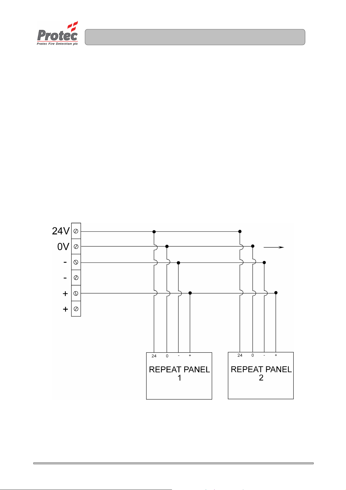
10.0 Repeat Panel Wiring
The 3300 can drive up to eight 3300 Repeat Panels directly from its External Expansion Interface port.
No extra driver boards are required.
The external expansion port has four connections, present on a terminal block labelled
‘EXT EXP’ on the Main PCB. These are:
1. +24V (fused at 100mA, self resetting (when overload and power is removed), non-monitored)
2. 0V
3. Data -
4. Data +
This port connects to all Repeat Panels and should be wired in screened cable to ensure compliance
with relevant EMC regulations. Figure 10.0 shows a typical installation.
Figure 10.0 Typical 3300 External Expansion Interface Installation.
To further
Repeat
Panels
www.acornfiresecurity.com
www.acornfiresecurity.com

93-530-70 Issue 0 Page 15 of 44 © Protec Fire Detection PLC 2007
11.0 Internal Expansion Port
The 3300 can accept various internal interfaces, these must be located within the 3300 panel
enclosure. The interfaces currently available are:
•Fire Link Interface, a maximum of one per panel.
•8 way Volt free contact zonal fire / fault mimic. A maximum of one per panel.
These interfaces connect using the 10 pin expansion port (J2) located at the middle left of the Main
PCB. If both the fire link and the 8 way mimic interfaces are used, the fire link must be connected to
the 3300 then the 8 way mimic to the fire link interface.
Consult the relevant interface installation sheet for further details.
www.acornfiresecurity.com
www.acornfiresecurity.com

93-530-70 Issue 0 Page 16 of 44 © Protec Fire Detection PLC 2007
12.0 Commissioning
12.1 Connecting the Mains
Important Note:
•Pay particular attention that the earth cable is firmly connected to the earth terminal of the
power supply, and that the earth strap from the power supply PCB to the earth post is
sound.
Ensure the fused double pole isolator is in the ‘OFF’ position then connect the incoming mains cable
to the appropriate terminals on the power supply PCB (see figure 12.0).
Figure 12.0 Power Supply Terminal Details
www.acornfiresecurity.com
www.acornfiresecurity.com

93-530-70 Issue 0 Page 17 of 44 © Protec Fire Detection PLC 2007
12.2 Installing and Connecting The Standby Batteries
The panel is designed to house two 12V 3.3Ah Valve Regulated Sealed Lead Acid (SLA) batteries.
These fit into the left hand compartment of the 3300 and should be secured with the Tie Wraps
provided.
The two batteries must be connected in series, a connecting link is supplied for this purpose.
The batteries must then be connected to the Power Supply PCB using the wires provided, please
observe polarity when connecting.
Ensure all spade connectors are pushed fully home onto the battery terminals.
Figure 12.1 shows the location and connection details for the batteries.
Figure 12.1 Installation of 3300 Standby batteries (shown with 3300 lid removed)
12.3 Switching On
Switch the fused isolator to the ‘ON’ position. The ‘Supply Present’ indicator should illuminate on the
front of the panel and, assuming all other connections are correct and the end of line units are present
(and the correct value) , no other faults should be displayed.
The 3300 is now ready to be programmed.
www.acornfiresecurity.com
www.acornfiresecurity.com

93-530-70 Issue 0 Page 18 of 44 © Protec Fire Detection PLC 2007
13.0 Programming Overview
The 3300 has many programming features, making it extremely flexible. These can be accessed by
users at different authorisation levels. The programming features and authorisation levels are detailed
below.
13.1 Access Levels
Access Level 1 (User code not entered)
The panel’s front panel display indicators are visible, providing a clear status of the 3300 at that time.
The functions that may be performed at access level 1 are:
•Muting of the panel’s internal buzzer.
•Entry of the 5 digit user code to access level 2 functions.
Access Level 2 (User code entered)
Only authorised users are permitted access to level 2 functions, these are:
•Silencing an alarm condition.
•Sounding the alarms.
•Resetting the panel after an alarm activation.
•Testing the front panel indications, and internal buzzer.
•Programming a zone into test mode (only one test zone at once is permitted).
•Disablement of detector circuits.
•Disablement of alarm circuits.
•Disablement of any programmed delays (detector and fire link).
•Disablement of the fire link interface (if fitted).
www.acornfiresecurity.com
www.acornfiresecurity.com

93-530-70 Issue 0 Page 19 of 44 © Protec Fire Detection PLC 2007
Access Level 3 (Engineer Controls)
Only engineers are permitted access to level 3 functions, these are:
•All level 2 functions, plus
•The setting of zone delay times.
•The programming of delayed zones.
•The programming of coincidence zones.
•The programming of non-latching zones.
•The programming of test zones (one, or more zones may be programmed).
•The programming of expansion interface data.
•Fault diagnosis features.
•Programming the end of line type.
•Programming the power supply type.
13.2 Zone Programming Choices
Each zone of the 3300 may be programmed in the following manner.
•Non-latching mode.
•Coincidence mode.
•Delay mode.
•Test mode.
Please not that a zone can only be programmed with one of the choices (ie. a zone cannot be set-up
as non-latching and delay) the last programmed choice will be accepted by the 3300.
NOTE: Test mode overrides all other programming.
www.acornfiresecurity.com
www.acornfiresecurity.com

93-530-70 Issue 0 Page 20 of 44 © Protec Fire Detection PLC 2007
14.0 Programming Details
In general the front panel buttons have the following alternate functions when the 3300 is in
programming mode.
When Access Level 3 programming functions are being performed the ‘Supply Present’ indicator will
flash.
Button 1 Toggle.
Button 2 Scroll.
Button 3 Accept.
Button 4 Back / Exit / Program.
14.1 Programming Zone Disablements
The 3300 can have one, or more, of its detector zones disabled. When a zone is disabled faults and
activations from that zone are inhibited.
1. From access level 1 enter your 5 digit user code 1 3 4 4 2 or turn the key-switch (depending on
the model purchased).
2. The ‘level 2 Accessed’ indicator will illuminate.
3. Press button 2 once – The ‘General Disablement’ indicator will illuminate steady to show the zone
disablement option is selected (the normal front panel display is temporarily replaced with the
programming display). Any current disablements will be displayed on row 1 of the display. Accept
the option by pressing button 3.
4. The ‘General Disablement’ indicator will flash, showing this option has been accepted.
5. Highlight the zone to be disabled by repeatedly pressing button 2.
6. Press button 1 to show that it is to be disabled / not disabled. The relevant row 1 indicator will be
illuminated if the zone is disabled.
7. Follow the procedure above until all zones that are to be disabled have their row 1 indicators
illuminated.
8. Press button 3 to return to the programming selection menu.
9. Press button 4 to accept and program the disablement set-up and return to access level 2.
10. The yellow ‘General Disablement’ indicator will be illuminated steady, as will the row 2
disablement indicator for the relevant zone(s).
www.acornfiresecurity.com
www.acornfiresecurity.com
This manual suits for next models
1
Table of contents
Popular Control Panel manuals by other brands

Sawo
Sawo ASV 3-15 operating instructions

Cooper Controls
Cooper Controls 2 Chilli Control Panel installation guide

Digital Equipment
Digital Equipment Pro-face FP2500-T12 installation guide

Bentel Security
Bentel Security KYO Series Programming guide

Ness
Ness R8 user manual

Vertiv
Vertiv Liebert EXL S1 user manual


schmersal
schmersal BDF 200 AS operating instructions

EasyGate
EasyGate D1 manual

Balboa Instruments
Balboa Instruments ML551 user guide

Donaldson Torit
Donaldson Torit Checker board Installation, Operation, Service and Replacement Part Information

CAME
CAME ZL19N installation manual

Khai An
Khai An QC2002 operating manual