Donaldson Company, Inc.
4
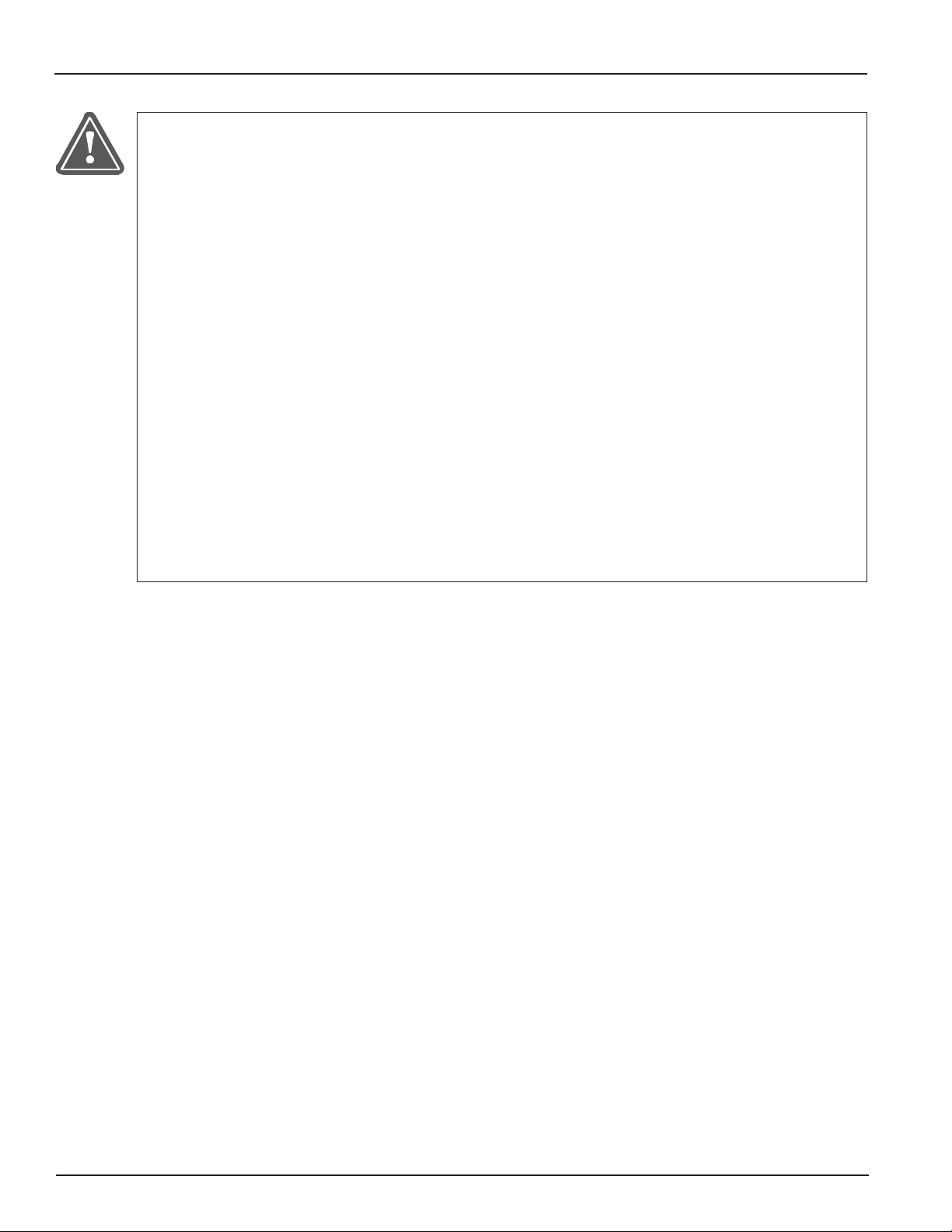
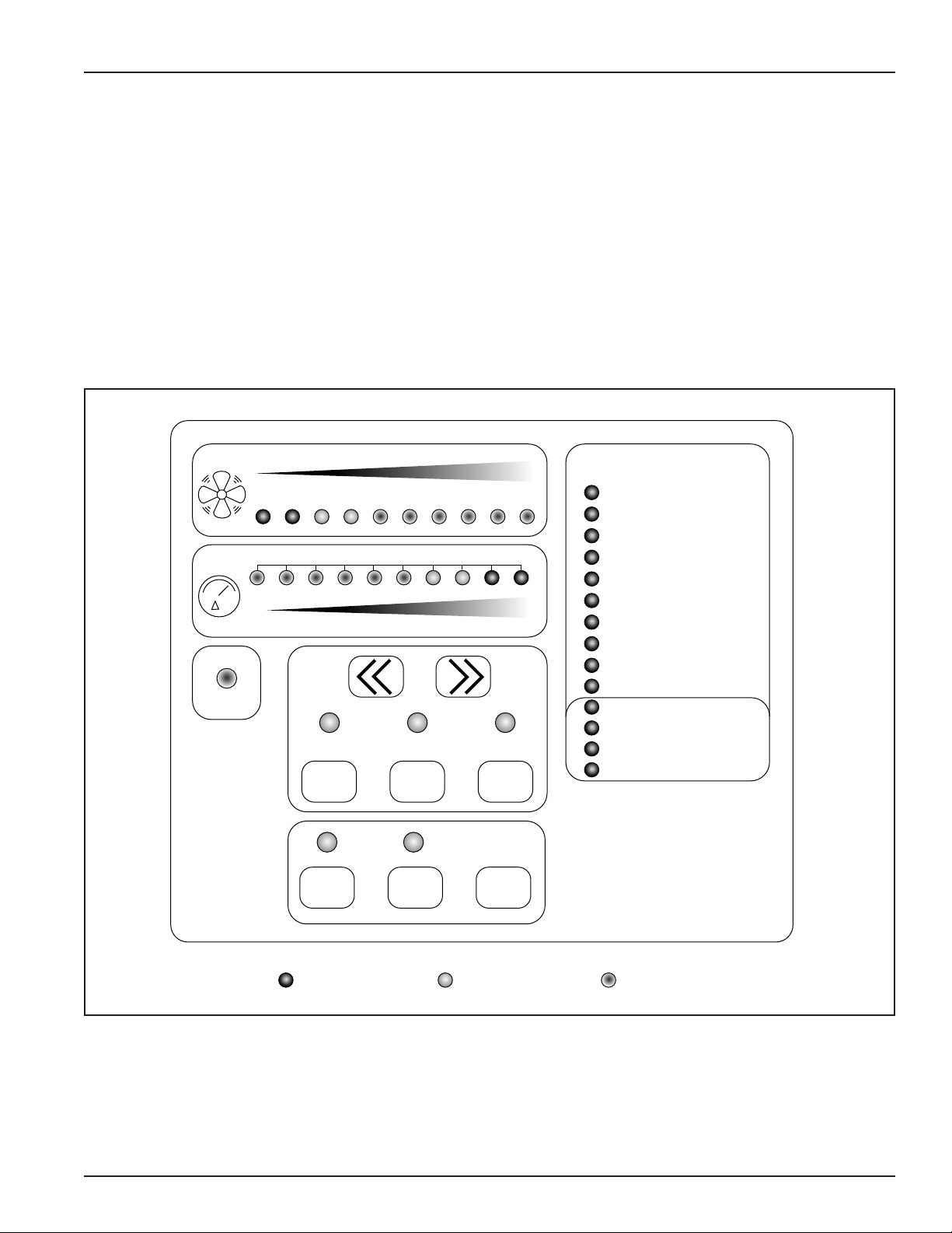
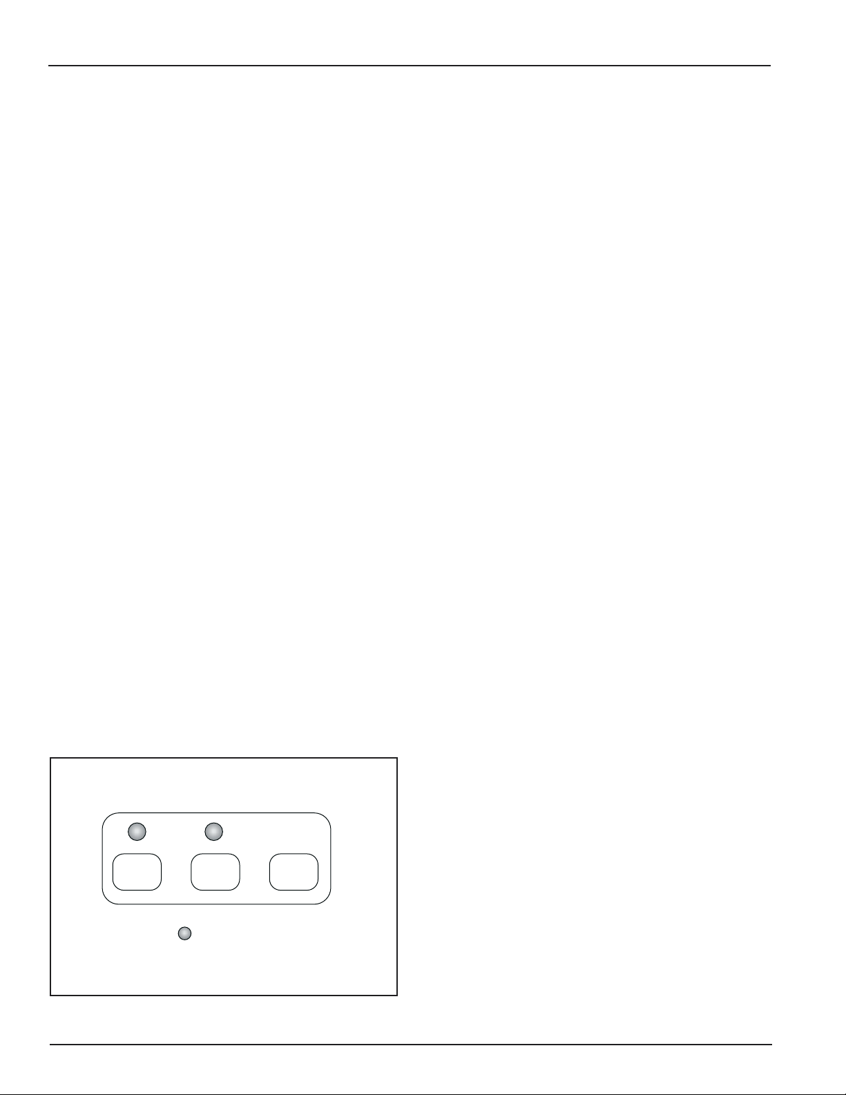
Checker board Control Panel
The Checker board provides cleaning control,
diagnostic review of the operational parameters,
diagnostic review of the system components, and a
record of operational data and fault conditions for
future review. The operator interface provides
control of unit functions and operational status
information.
The design allows for a host computer to remotely
control the unit, change operational parameters,
and check operational status.
Inspection on Arrival
1. Unpack and open the Checker board enclosure
by loosening the clamp screws on the sides.
Remove packing materials. Compare
components received with the packing list.
2. Inspect unit on delivery.
3. Report any damage to the delivery carrier.
4. Request a written inspection report from the
Claims Inspector to substantiate claim.
5. File claims with the delivery carrier.
6. Report incomplete shipments to the delivery
carrier and your Donaldson representative.
Items shipped loose include:
Control box Safety filter
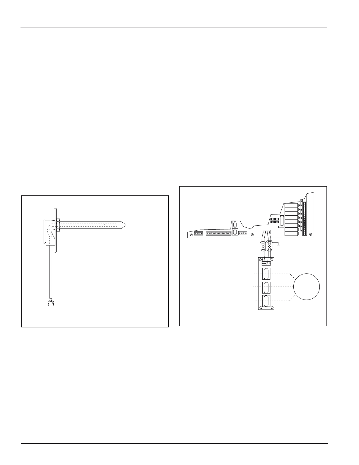
Current sensor board Connector, tube to tube
Twisted pair cables Print 3EA-37129
Clear tubing, two 35-ft Label stickers, 1/4 x 4-in
Black tubing, 35-ft long
Tools Required
Wire strippers Wire cutter
Knife Needle nose pliers
Crescent wrench Channel lock pliers
Screw driver, 5/16-in wide and 9/64-in narrow slot tip
Hole knockout: 1/2-in connector use .859 to .906
and for 3/4-in connection use 1.094 to 1.141.
Supplies Required
Conduit, 1/2 and 3/4-in Grounding lugs
Elbow connectors Wire ties
Straight connectors Wire nuts
Wire, green/white/black/red, #16, 14, or 12 awg
Operation
The Checker board is used to control, diagnose,
and troubleshoot Donaldson Torit dust collectors.
The microprocesser-based control can be
programmed to control solenoid valves used for
filter cleaning, control the blower motor starter,
control setpoints used to start and stop the filter
cleaning operation, monitor and diagnose the
mechanical and electronic system components, and
store diagnostic readings for up to one year.
Operating system parameters, abnormal operating
conditions, and mechanical failure messages appear
on the Checker board display. It also allows a host
computer to control the unit, change operational
parameters, and check operational status from a
remote location.
Pulse Cleaning Operation
The Checker board can be set to control the filter
cleaning operation of the unit, including starting
and stopping at adjustable setpoints, initiating the
pulse, pulse sequence, and pulse duration. The
Checker board also provides the logic to control
alternate cleaning modes.
The microprocessor compares the sensor readings
with the stored values to determine the operational
health of the system. This comparison can indicate
ruptured or plugged filters, cleaning system
component malfunction, excessive temperature,
and blower motor overload due to excess air flow
or motor failure. The microprocessor also has an
extensive self-diagnostic test program that provides
technical assistance to the service technician when
necessary.