Pts E-Kit AN-150 User manual

PTS E-Kit™User Guide for
AN/PRC-150 E-Kit™
Table of Contents:
1. E-Kit™Major Items List
2. PSDS Overview & Parts List
3. Power Source Part List
4. AntennaSystem VHF/UHF Parts List
5. AntennaSystem HF Parts List
6. HF Antenna Setup
7. InterconnectionDiagrams
8. Concept of Operations& Best Practices
9. Maintenance,Warranty & Contact Information
Failure to follow all instructionsand guidance provided in E-Kit™system manuals
may result in system failure and/or personnel injury. It is highly recommended
for all personnel to review all instructions and warnings when employing E-Kit™
systems and components prior to operations.
For additional guidance in setup and operations, please reference the full manuals
contained within the kit.
www.pts-inc.com | info@pts-inc.com | 256-539-6787 | 1318-B Putman Drive Huntsville, AL 35816
Rev 1.1

Parts List / Major End Items
E
-Kit™
ITEM #
QTY
PER KIT
PART NUMBER DESCRIPTION
1 1
AS0150
-HR-150
Harris 160 Single AC/DCPowerSupplyDocking Stationw/Manual
2 1
ANT
-WWS-000101-2-
1
Antenna
- HF Dipole 150W ExpeditionaryBroadband
(2
-30 MHz)
3 1
ANT
-RTL-307005-1-1
Antenna
- IAMD - 7m 3" (Dual Band: 30-88 & 225-512 MHz) - Multicam
4 1
ACC
-RTL-002105
SecondaryCollar
- 3" - Used withSingle Tube Mast (NotPictured)
5 1
CAB.OTH.101
Cable
- LMR 400, 100'
6 1
PWR
-BTR-00203
PowerSource, UPS, 6
-PK Tan Bay
7 6
PWR
-BTR-00103
Battery, Li
-ion, BB-2590, 294WH
8 1
CAB.APW.101
Cable
- AC Inputfor6 PK DC PowerSource
9 1
CAB.DPW.101H
Cable
- Harris Straight6 PKDC PowerSource to PSDS
10 1
PWR
-BTR-12001
120W SolarCharging Panels(2PanelsperSet,
Deluxe KitOnly)
11 1
CAB.APW.102
Cable
- DC Solar ChargingOutputto 6 PK Power Source (Deluxe KitOnly)
12 1
CAB.APW.102E
Cable
-Solar Charging Extension 8’ (Deluxe KitOnly)
13 1
ACC
-SLY-01230
Single SidedHeadset w/Noise Canceling Microphone
14 1
PAC.TXC.101
Transit Case w/ Foam
–Large (Not Pictured)
15 1
PAC.TXC.106
Transit Case w/ Foam
–Medium(NotPictured)
2

Power Supply Docking Station (PSDS)
# Qty PSDS Components
1 1 AS0150-HR-150 (PSDS)
2 1 110V AC PWR Cable
3 1 Audio Jumper –J3
2. 110V AC PWR Cable
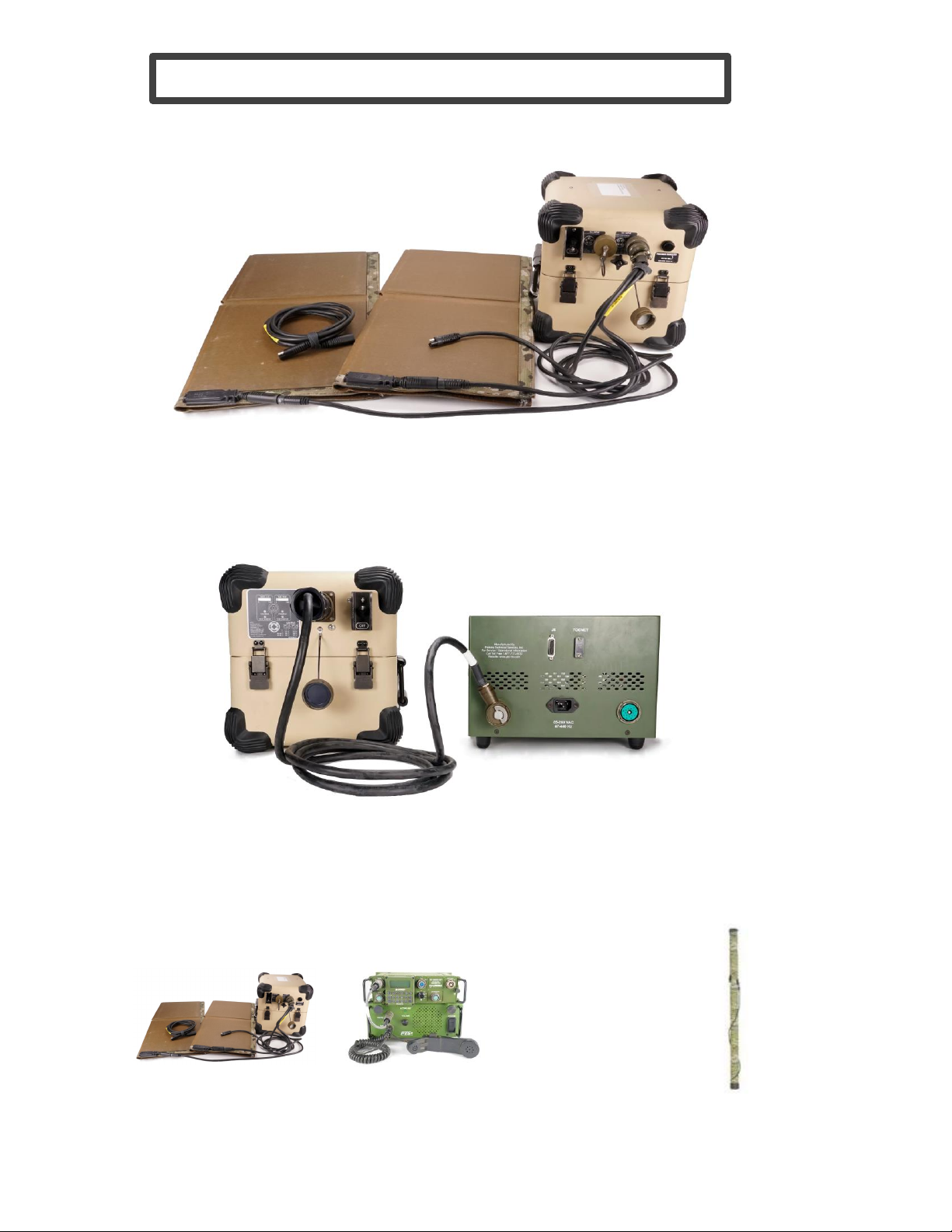
3
For additional guidancein setup and
operations, pleasereference the full
manuals contained within the kit.
3. Audio Jumper AS0150-HR-150 shown with unitsupplied
radio and accessories
1. AS0150-HR-150
PSDS for AN/PRC-117G Tactical Radio
# AS0150-HR-150 Rear Ports
1120-240VAC PWR Input
2 24V DC PWR Input
3 TOCNET Port, See manual
4LS-671 Remote Audio, See manual
5 J9 Digital Port,See manual

Power Source & Solar Kit
1. PWR-BTR-00203
24V DC PWR Source with AC PWR CableConnected
# Qty Power Source Components
1 1 PWR-BTR-00203, 24VDC Power Source
2 1
CAB.DPW.101S, SINCGARS Straight Power Source to PSDS
3 1
CAB.APW.101, 110V AC PWR Cable
4 1
CAB.APW.102, Solar InputCable
(Deluxe Kit Only)
5 1
CAB.APW.102E, Solar InputCable Extension (Deluxe Kit Only)
6 2
PWR.BTR.12001, 120W Solar Panel Kit
(Deluxe Kit Only)
7 6 Battery, Li-ion,BB-2590, 294WH(Not Pictured)
2. CAB.DPW.101H
3. CAB.APW.101
4. CAB.APW.102
5. CAB.APW.102E
6. PWR.BTR.12001
4
For additional guidancein setup and
operations, pleasereference the full
manuals contained within the kit.
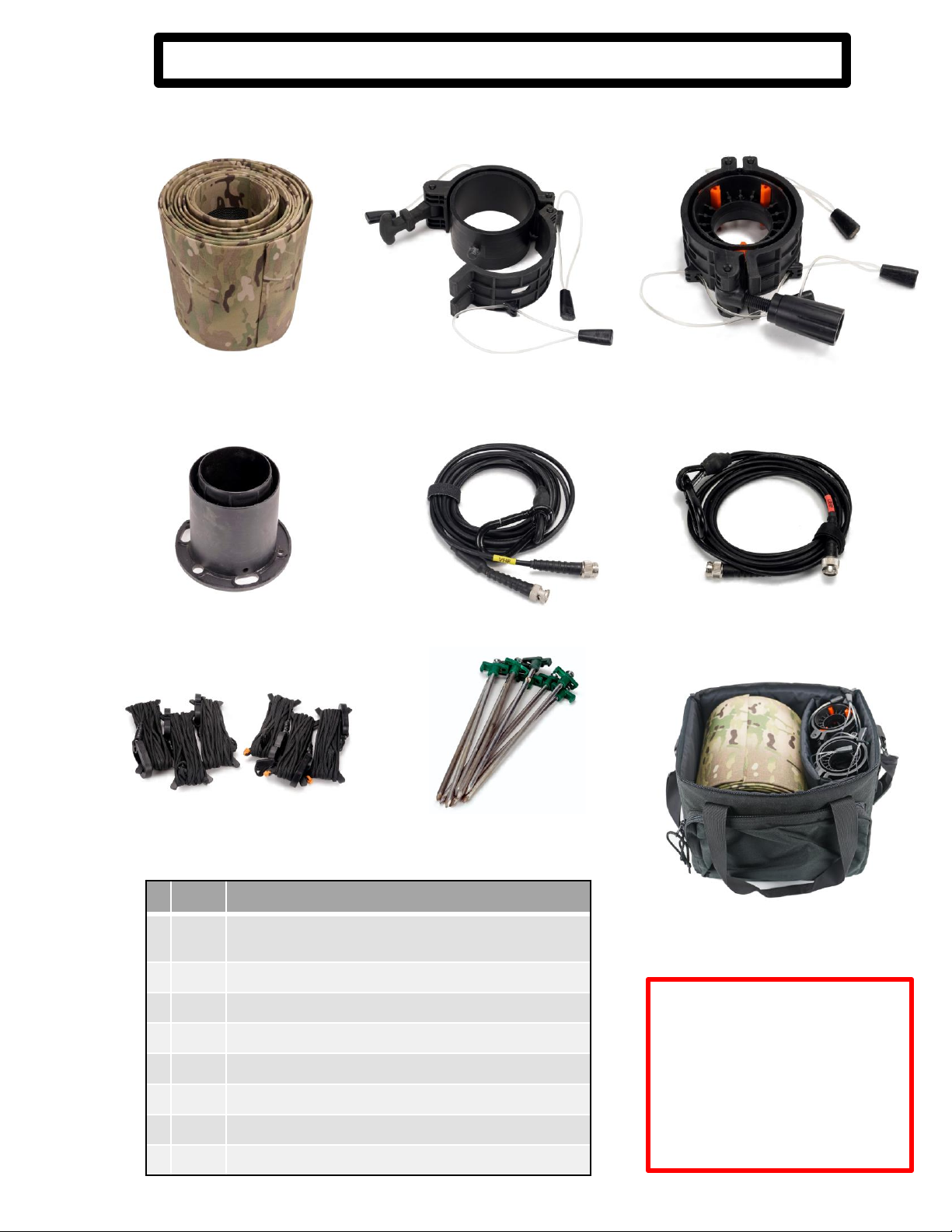
Antenna System –VHF/UHF
#
Qty ANT-RTL-307005-1-1 Antenna Components
1
1ANT-RTL-307005-1-1 7m 3” VHF/UHF Integrated
Antenna MastSystem
2
1
Top Collar
3
1
Secondary Collar
4
1
BaseCap
5
1
VHF Connection Cable(BNC Female Connection)
6
1
UHF Connection Cable(TNC Female Connection)
7
6
Guy Ropes (3 per Top and Secondary Collars)
8
9
Guy WireStakes (Rock Pegs)
1. ANT-RTL-307005-1-1 2. Top Collar 3. Secondary Collar
4. Base Cap 5. VHF Connection Cable 6. UHF Connection Cable
7. Guy Ropes 8. Guy Wire Stakes (Rock Pegs)
5
WARNING:
Failure to use the included
VHF/UHF connection cables as
feedline strain relief will cause
system failure.
For additionalguidance in setup and
operations, please reference the full
manualscontainedwithin the kit.
Antenna System
ShownBagged

6
AntennaSystem –HF
#
Qty ANT-WWS-000101-2-1 Antenna Components
1
1 Balun (150W AVG, Type N Female Connector)
2
1RF Load
3
2Antenna Half
4
2Tie Downs
5
1
Hoist Rope with Throw Weight
6
1
Antenna Feedline (Type N to BNC Male)
7
1
Radial Set
1. Balun 2. RF Load
5. Hoist Rope3. Antenna Half 4. Tie Downs
6. Antenna Feedline 7. Radial Set
For additional guidancein setup and
operations,pleasereference the full
manuals contained within the kit.
Antenna System
Shown Bagged

HF Antenna Setup
5
The 7m Integrated Mast Antenna system(IAM-D, pn. ANT-RTL-307005-1) provides an excellent mounting
solutions to deploying the E-Kit included HF antenna system. This combination of antenna systems
provide a multiband antenna field that is both quickly erected and has a small footprint. Both antenna
systems must be installed using the user provided instruction manuals. Additional instructions for using
the IAM-D as a masting systemis contained within this document.
HF antenna to IAM-D integration steps:
1. Install the included secondary collar approximately 1’ below the IAM top collar (Figure 1).
Using the secondary collars lanyards, install included D-ring (or equivalent) then feed the hoist rope thru
the D-ring (Figure 2). Secure the hoist rope to ground stake at the base of the IAM-D. This stepshould
be completed while erecting the IAM-D after the top cap is installed. This configuration will provide a
pulley systemthat will allow the HF antenna systemto vary in height as required.
2. Once the IAM-D is fully erected and guy lines are tensioned, attach the HF antenna load and
balun to the hoist rope with supplied snap links (Figure 3). Ensure that the HF antenna can be cleanly
pulled up by the hoist rope.
3. Attach the two wire antenna segments to the load/balun assemblies and supplied feedline per
the HF antenna systemmanuals (Figure 4).
4. Hoist the assembled HF antenna to the required height based on mission requirements (for
additional information on antenna configurations, please reference the supplied manual) and carefully
route and secure the extended HF wire antenna segments to avoid interference with the IAM-D guy
lines. Once the HF antenna is hoisted to the appropriate height, secure the pull side of the hoist rope to
a ground stake or similar item ensuring the HF antenna will not fall.
Figure 2 Figure 3
Figure 4
Figure 1
E-Kit™Interconnect Diagram
Power Source connected to optional solar panels
(Note: Power Source can support up to 3 solarpanels)
6
TOC Area
Power Source & PSDS connected with
100’ feedline (CAB.OTH.101) Antenna
>75’ from TOC
Typical field setup for Field Operations
Power Supply connected to PSDS 24V DC Inputs.
(Shown with CAB.DPW.101H connected)

PTS E-Kit™Concept of Operations& Best Practices
The PTS Expeditionary Kit (E-Kit™) for Tactical Radios is a self-contained ancillary kit that supports
tactical communications in a light-weight, easily usable package. The E-Kit™contains the following: 1.
Power Supply Docking Station (PSDS) that mounts the radios and supplies regulated power and audio
outputs; 2. Power Source that can provide two amplified radios power for multiple days and can be
recharged via AC, DC or solar inputs; and 3. lightweight antenna systems tuned for High Frequency (HF)
communications.
The E-Kit™components are connected per instructions in this user guide and further information
may be gained by review of the provided manuals for each component contained within the kit. The E-
Kit™components do not change the basic functions of the tactical radio systems andwill not interfere
with tactical communications with respect to COMSEC, range or functionality. The PTS E-Kit™is meant
to augment the currently fielded tactical radio mounts, power sources and antenna systems. The E-Kit™
may be combined with currently fieldedancillaries as needed by the end users' requirements.
The E-Kit™components are designed for operation in austere environments. The power source
and antenna systems are waterproof but the PSDS, due to its design, must be protected against direct
water intrusion or immersion. The PSDS and antenna systems are designed for operations at the halt
and not designed for usage in vehicle systems or to replace installed vehicle installation kits. Standard
protections against RF and other electrical hazards should be employed per regulatory
guidance. Antenna systems should be employed using local guidance and regulations with regard to
personnel safety.
The E-Kit™is designed to be employed by a minimum of 2 personnel. Using less personnel than
recommended may cause systemdamage and/or injury to personnel. E-Kit™transportation cases may
weigh in excess of 100lbs and are considered to be a “two man” lift.
The E-Kit™is employed by first determining the best footprint for the systembased on the
maximum cable lengths between the PSDS, power source and antenna system. The included 100’
LMR400 feedline will yield approximately 95’ of separation, it is recommended to separate antenna
systems to reduce the likelihood of interference. The E-Kit™includes specified feedline for the antenna
system, usage of other cable may reduce performance and/or cause damage to the antenna. If solar
charging is the primary method of resupplying power, additional planning will be required based on the
length of the solar charging cables and extensions.
The E-Kit™power source is recommended to be fully charged prior to operation. The power
source may be charged via AC or DC power with the batteries installed, or the batteries may be removed
and charged with approved bulk charge systems. Using the two solar panels included in the Deluxe Kit
on a sunny day, the systemmay be fully charged within 8 hours. The power source will provide 24VDC
power with a minimum of 2 batteries (1 battery per bank) and the batteries may be swapped while the
systemis operational. When connected to AC power, the power source will act as a universal power
supply (UPS) should external AC power be lost. Additional charging and output options are available,
please see manual for full capabilities and options.
Failure to follow all instructions and guidance provided in E-Kit™systemmanuals may result in
systemfailure and/or personnel injury. It is highly recommended for all personnel to review all
instructions and warnings when employing E-Kit™systems and components prior to operations.
7

www.pts-inc.com | info@pts-inc.com | 256-539-6787 | 1318-B Putman Drive Huntsville, AL 35816
WarrantyInformation
Replacement manuals, user guides and other documentation for each PSDS and E-Kit™is
available on the PTS Website, www.PTS-INC.com.
For additional information or help, contact PTS Sales
sales@pts-inc.comor call (256) 539-6786 or 1 (877) 737-5832.
For repairs or replacement parts, contact PTS Support
support@pts-inc.com or call (256) 539-6786 or 1 (877) 737-5832.
ContactInformation
PTS warrants all power supply docking stations and transit cases furnished under contract are
free from defects in material and workmanship and will conform to all requirements of the
contract. The PTS PSDS warranty shall be for a period of thirty-six (36) months from the date of
the receipt by the user. Products sold by but not manufactured by PTS will be covered by the
Original Equipment Manufacturers (OEM) warranty policies and procedures.
MaintenanceInformation
PTS E-Kit™components are COTS (commercial off-the-shelf) Class IX equipment and
maintenance beyond general cleaning is not authorized. Referto the component specific
manuals for user level cleaning/maintenance practices. The Original Equipment Manufacturer
(OEM) is the depot level for repairs; if an individual component fails or becomes damaged,
please contact PTS for troubleshooting and further instructions.
This manual suits for next models
1
Table of contents
Other Pts Antenna manuals

Popular Antenna manuals by other brands


Sirio Antenne
Sirio Antenne MG 75 installation manual

COBHAM
COBHAM SAILOR 600 Viasat Ka Installation and operation manual

Goobay
Goobay DIA-90 PS Assembly instructions

TP-Link
TP-Link TL-ANT5830B Quick installation guide

Lancom
Lancom AirLancer ON-Q60ag Mounting instructions

SolarEdge
SolarEdge Cellular Plug-In installation guide


