Pts E-Kit SR-4A User manual

PTS E-Kit™User Guidefor
SR-4A (ASIP) E-Kit™
Table of Contents:
1. E-Kit™Major Items List
2. PSDS Overview & Parts List
3. Power Source PartList
4. AntennaSystemParts List
5. InterconnectionDiagrams
6. Conceptof Operations & Best Practices
7. Maintenance,Warranty&ContactInformation
Failure to follow all instructions and guidance provided in E-Kit™
system manuals may result in system failure and/or personnel injury. It
is highly recommended for all personnel to review all instructions and
warnings when employing E-Kit™systems and components prior to
operations.
For additional guidance in setup and operations, please reference the full
manuals contained within the kit.
www.pts-inc.com | info@pts-inc.com | 256-539-6787 | 1318-B Putman Drive Huntsville, AL 35816
Rev 1.1

Parts List / Major End Items
E-Kit™
ITEM # QTY
PER KIT
PART NUMBER DESCRIPTION
1 1
AS0004
-SR-4AE-OD
SINCGARS 1523 ASIP Dual AC/DC Power Supply DockingStation
- Olive Drab -
ExpeditionaryUnitw/ Manual
2 2
ANT
-RTL-307005-1-
1
Antenna
- IAM D - 7m 3" (Dual Band: 30-88 & 225-512 MHz) - Multicam
3 2
CAB.OTH.101
Cable
- LMR 400, 100'
4 1
PWR
-BTR-00203
PowerSource, UPS, 6
-PK Tan Bay
5 6
PWR
-BTR-00103
Battery, Li
-ion, BB-2590, 294WH
6 1
CAB.APW.101
Cable
- AC Inputfor6 PK DC PowerSource
7 1
CAB.DPW.101S
Cable
- SINCGARS Straight6 PK DC PowerSource toPSDS
8 1
CAB.DPW.102S
Cable
- "Y" for Dual SINCGARSPSDS
9 1
PWR
-BTR-12001
120W SolarChargingPanels (2PanelsperSet)
(Deluxe KitOnly)
10 1
CAB.APW.102
Cable
- DC Solar ChargingOutputto 6 PK PowerSource (Deluxe KitOnly)
11 1
CAB.APW.102E
Cable
-Solar Charging Extension 8’ (Deluxe KitOnly)
12 1
AS0004
-RTC
Cable
- SINCGARS Retrans (17")
13 1
ACC
-SLY-01230
Single SidedHeadsetw/ Noise Canceling Microphone
14 2
PAC.TXC.101
TransitCase w/ Foam
–Large (Not Pictured)
2
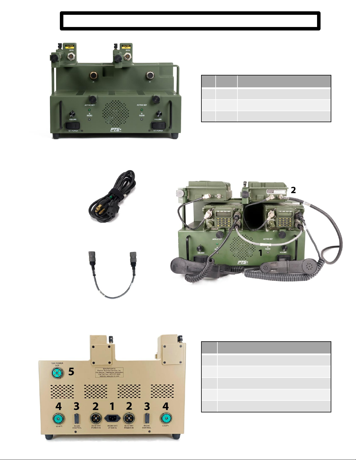
1. PTS AS0004-SR-4A OD
PSDS for RT-1523 (ASIP) Tactical Radios
Power Supply DockingStation (PSDS)
# AS0004-SR-SR4A Rear Ports
1120-240VAC PWR Input
2 24V DC PWR Input
3 TOCNET Port, See manual
4LS-671 Remote Audio, See manual
5 24V DC PWR Out, 5A Max
# Qty PSDS Components
1 1 AS0004-SR-SR4A OD (PSDS)
2 1 110V AC PWR Cable
3 1 AS0004-RTC (RETRANS Cable)
2. 110V AC PWR Cable
3. AS0004-RTC
AS0004-SR-SR4A shown with unitsupplied radios and cables populated.
1. AS0004-RTC RETRANS Cable,2. Feedline and PA jumpers
3
For additional guidancein setup and
operations,pleasereference the full
manuals contained within the kit.

Power Source &Solar Kit
1. PWR-BTR-00203
24V DC PWR Source with AC PWR CableConnected
# Qty Power Source Components
1 1 PWR-BTR-00203, 24VDC Power Source
2 1
CAB.DPW.102S, "Y" for Dual SINCGARS PSDS
3 1
CAB.DPW.101S, SINCGARS Straight Power Source to PSDS
4 1
CAB.APW.101, 110V AC PWR Cable
5 1
CAB.APW.102, Solar InputCable
(Deluxe Kit Only)
6 1
CAB.APW.102E, Solar InputCable Extension (Deluxe Kit Only)
7 2
PWR.BTR.12001, 120W Solar Panel Kit
(Deluxe Kit Only)
8 6
Battery, Li
-ion, BB-2590, 294WH (Not Pictured)
3. CAB.DPW.101S
2. CAB.DPW.102S
4. CAB.APW.101
5. CAB.APW.102
6. CAB.APW.102E
7. PWR.BTR.12001
4
For additional guidancein setup and
operations,pleasereference the full
manuals contained within the kit.

AntennaSystem
#
Qty ANT-RTL-307005-1-1 Antenna Components
1
1ANT-RTL-307005-1-1 7m 3” VHF/UHF Integrated
Antenna MastSystem
2
1
Top Collar
3
1
Secondary Collar
4
1
BaseCap
5
1
VHF Connection Cable(BNC Female Connection)
6
1
UHF Connection Cable(TNC Female Connection)
7
6
Guy Ropes (3 per Top and Secondary Collars)
8
9
Guy WireStakes (Rock Pegs)
1. ANT-RTL-307005-1-1 2. Top Collar 3. Secondary Collar
4. Base Cap 6. VHF Connection Cable
5. UHF Connection Cable
Antenna System
Shown Bagged
7. Guy Ropes 8. Guy Wire Stakes (Rock Pegs)
5
WARNING:
Failure to use the included
VHF/UHF connection cables as
feedline strain relief will cause
system failure.
For additionalguidance in setup and
operations, please reference the full
manualscontainedwithin the kit.

E-Kit™InterconnectDiagram
Power Source connected to optional solar panels
(Note: Power Source can support up to 3 solar panels when connected to the CAB.APW.102
DC Solar input cable)
6
TOC Area
Power Source & PSDS connected with 100’ LMR400 feedline (CAB.OTH.101)
Antenna 2
>75’ from TOC
Antenna 1
>75’ from TOC
Typical field setup for RETRANS Operations
Power Source connected to PSDS 24V DC Inputs
(Note: The supplied Straight PWR Cable (CAB.DPW.101S) is used to power one side of a Dual PSDS and
combined with the “Y” PWR Cable (CAB.DPW.102S) to provide DC power to both sides or the PSDS.)

PTS E-Kit™Concept of Operations& BestPractices
The PTS Expeditionary Kit (E-Kit™) for RT-1523 (ASIP) Tactical Radios is a self-contained ancillary
kit that supports tactical communications in a light-weight, easily usable package. The E-Kit™contains
the following: 1. Power Supply Docking Station (PSDS) that mounts the radios and supplies regulated
power and audio outputs; 2. Power Source that can provide two amplified radios power for multiple
days and can be recharged via AC, DC or solar inputs; and 3. lightweight antenna systems tuned for
VHF/UHF line of sight communications.
The E-Kit™components are connected per instructions in this user guide and further information
may be gained by review of the provided manuals for each component contained within the kit. The E-
Kit™components do not change the basic functions of the tactical radio systems and will not interfere
with tactical communications with respect to COMSEC, range or functionality. The PTS E-Kit™is meant
to augment the currently fielded tactical radio mounts, power sources and antenna systems. The E-Kit™
may be combined with currently fielded ancillaries as needed by the end users' requirements.
The E-Kit™components are designed for operation in austere environments. The power source
and antenna systems are waterproof but the PSDS, due to its design, must be protected against direct
water intrusion or immersion. The PSDS and antenna systems are designed for operations at the halt
and not designed for usage in vehicle systems or to replace installed vehicle installation kits. Standard
protections against RF and other electrical hazards should be employed per regulatory
guidance. Antenna systems should be employed using local guidance and regulations with regard to
personnel safety.
The E-Kit™is designed to be employed by a minimum of 2 personnel. Using less personnel than
recommended may cause systemdamage and/or injury to personnel. E-Kit™transportation cases may
weigh in excess of 100lbs and are considered to be a “two man” lift.
The E-Kit™is employed by first determining the best footprint for the systembased on the
maximum cable lengths between the PSDS, power source and antenna system. The included 100’
LMR400 feedline will yield approximately 95’ of separation. For RETRANS missions, utilizing both
included antenna systems, it is recommended to separate the antenna to the maximum space available
to reduce the likelihood of interference. The E-Kit™includes specified feedline for the antenna system,
usage of other cable may reduce performance and/or cause damage to the antenna. If solar charging is
the primary method of resupplying power, additional planning will be required based on the length of
the solar charging cables and extensions.
The E-Kit™power source is recommended to be fully charged prior to operation. The power
source may be charged via AC or DC power with the batteries installed, or the batteries may be removed
and charged with approved bulk charge systems. Using the two solar panels included in the Deluxe Kit
on a sunny day, the systemmay be fully charged within 8 hours. The power source will provide 24VDC
power with a minimum of 2 batteries (1 battery per bank) and the batteries may be individually swapped
while the systemis operational. When connected to AC power, the power source will act as a universal
power supply (UPS) should external AC power be lost. Additional charging and output options are
available, please see manual for full capabilities and options.
Failure to follow all instructions and guidance provided in E-Kit™systemmanuals may result in
systemfailure and/or personnel injury. It is highly recommended for all personnel to review all
instructions and warnings when employing E-Kit™systems and components prior to operations.
7

WarrantyInformation
Replacement manuals, user guides and other documentation for each PSDS and E-Kit™is
available on the PTS Website, www.PTS-INC.com.
For additional information or help, contact PTS Sales
sales@pts-inc.comor call (256) 539-6786 or 1 (877) 737-5832.
For repairs or replacement parts, contact PTS Support
support@pts-inc.com or call (256) 539-6786 or 1 (877) 737-5832.
www.pts-inc.com | info@pts-inc.com | 256-539-6787 | 1318-B Putman Drive Huntsville, AL 35816
ContactInformation
PTS warrants all power supply docking stations and transit cases furnished under contract are
free from defects in material and workmanship and will conform to all requirements of the
contract. The PTS PSDS warranty shall be for a period of thirty-six (36) months from the date of
the receipt by the user. Products sold by but not manufactured by PTS will be covered by the
Original Equipment Manufacturers (OEM) warranty policies and procedures.
MaintenanceInformation
PTS E-Kit™components are COTS (commercial off-the-shelf) Class IX equipment and
maintenance beyond general cleaning is not authorized. Refer to the component specific
manuals for user level cleaning/maintenance practices. The Original Equipment Manufacturer
(OEM) is the depot level for repairs; if an individual component fails orbecomes damaged,
please contact PTS for troubleshooting and further instructions.
Table of contents
Other Pts Power Supply manuals


Popular Power Supply manuals by other brands


Banner
Banner PSA-24 Specification sheet

Campbell
Campbell PS200 user guide

Emerson
Emerson Universal-R Installing and operating instructions

Guntermann & Drunck
Guntermann & Drunck MultiPower-6-NT installation guide

PCE Health and Fitness
PCE Health and Fitness PCE-PPS3300 Series user manual

Pepperl+Fuchs
Pepperl+Fuchs PS1000-A6-24.20 technical information

Conrad
Conrad 97 34 53 operating instructions

Whelen Engineering Company
Whelen Engineering Company UPS69024 installation guide

Rosewill
Rosewill RV-430-2-FRB user manual

HP
HP 6236B Operating and service manual

Siemens
Siemens SIDOOR ATD400S operating instructions

Lucent Technologies
Lucent Technologies Galaxy Power System 4812 product manual