EnerSys alpha Cordex CXRF 48-3.6kW Quick start guide

Alpha Modular Switched Mode
RectifierSystem
Models:
Cordex®CXRF 48-3.6kW
Cordex®HP CXRF 48-4kW, 48-4.6kW, 48-12kW
Technical Guide: 9400000-J0
Effective: 06/2020


Modular Switched Mode Rectier System
Models: Cordex® CXRF HP 48-12kW
Cordex® CXRF HP 48-4.0kW
Cordex® CXRF HP 48-4.6kW
Cordex® CXRF 48-3.6kW
For technical support, contact Alpha Technologies:
Canada and USA: 1-888-462-7487
International: +1-604-436-5547
Email: [email protected]
Copyright
Copyright © 2020 Alpha Technologies Ltd. All rights reserved. Alpha is a registered trademark of Alpha Technologies.
No part of this documentation shall be reproduced, stored in a retrieval system, translated, transcribed, or transmit-
ted in any form or by any means manual, electric, electronic, electromechanical, chemical, optical, or otherwise
without prior explicit written permission from Alpha Technologies.
This document, the software it describes, and the information and know-how they contain constitute the proprietary,
confidential and valuable trade secret information of Alpha Technologies, and may not be used for any unauthorized
purpose, or disclosed to others without the prior written permission of Alpha Technologies.
The material contained in this document is for information only and is subject to change without notice. While
reasonable efforts have been made in the preparation of this document to assure its accuracy, Alpha Technologies
assumes no liability resulting from errors or omissions in this document, or from the use of the information contained
herein. Alpha Technologies reserves the right to make changes in the product design without reservation and with-
out notification to its users.
Alpha®shall not be held liable for any damage or injury involving its enclosures, power
supplies, generators, batteries, or other hardware if used or operated in any manner or
subject to any condition inconsistent with its intended purpose, or if installed or oper-
ated in an unapproved manner, or improperly maintained.
Photographs contained in this manual are for illustrative purposes only. These photo-
graphs may not match your installation.
NOTE:
Operator is cautioned to review the drawings and illustrations contained in this manual
before proceeding. If there are questions regarding the safe operation of this powering
system, contact Alpha Technologies or your nearest Alpha representative.
NOTE:
NOTE:

9400000-J0 Rev E
2
Table of Contents
1. Safety ....................................................................................................................................5
1.1 Safety Symbols .......................................................................................................................... 5
1.2 General Safety ........................................................................................................................... 5
1.3 Mechanical Safety ...................................................................................................................... 5
1.4 Electrical Safety ......................................................................................................................... 6
1.5 Battery Safety ............................................................................................................................ 6
2. Introduction ...........................................................................................................................7
2.1 Scope of the Manual .................................................................................................................. 7
2.2 Product Overview ....................................................................................................................... 7
3. Specications ........................................................................................................................8
4. Features ..............................................................................................................................11
4.1 Rectier .....................................................................................................................................11
4.2 Cordex® HP Controller (CXC HP) ............................................................................................ 15
5. Inspection............................................................................................................................17
5.1 Packing Materials ..................................................................................................................... 17
5.2 Check for Damage ................................................................................................................... 17
5.3 General Receipt of Shipment ................................................................................................... 17
6. Installation ...........................................................................................................................18
6.1 Safety Precautions ................................................................................................................... 18
6.2 Tools Required ......................................................................................................................... 18
6.3 Power System Assembly and Mounting ................................................................................... 19
7. Wiring ..................................................................................................................................20
7.1 Grounding ................................................................................................................................ 20
7.2 AC Feeder Protection/Sizing .................................................................................................... 20
7.3 AC Wiring ................................................................................................................................. 21
7.4 DC Wiring ................................................................................................................................. 21
7.5 CAN Serial Ports ...................................................................................................................... 22
7.6 Shelf ID Connection ................................................................................................................. 23
7.7 Signal Wiring Connections to L-ADIO Board ........................................................................... 24

3
9400000-J0 Rev E
8. System Startup ...................................................................................................................26
8.1 Check System Connections ..................................................................................................... 26
8.2 Verify AC and Power the Rectier Shelf ................................................................................... 26
8.3 Triple Check Battery Polarity and Connections ........................................................................ 26
8.4 CXC HP Reset ......................................................................................................................... 26
9. Operation ............................................................................................................................27
9.1 Main Rectier States ................................................................................................................ 27
9.2 Main Rectier Modes ............................................................................................................... 27
9.3 Factory Ranges and Defaults .................................................................................................. 29
10. Maintenance .....................................................................................................................30
10.1 Replacing a Rectier Module ................................................................................................. 30
10.2 Fan and Fan Filter Replacement ........................................................................................... 31
10.3 MOV Replacement ................................................................................................................. 35
11. Acronyms and Denitions ..................................................................................................39
12. Warranty and Service Information ....................................................................................40
12.1 Technical Support .................................................................................................................. 40
12.2 Warranty Statement ............................................................................................................... 40
12.3 Product Warranty ................................................................................................................... 40
12.4 Battery Warranty .................................................................................................................... 40
12.5 Warranty Claims ..................................................................................................................... 40
12.6 Service Information ................................................................................................................ 40
13. Certication .......................................................................................................................41

9400000-J0 Rev E
4
List of Figures
Figure 1 — Cordex 48-3.6kW ........................................................................................................... 7
Figure 2 — Cordex 48-4kW/4.6kW ................................................................................................... 7
Figure 3 — Cordex 48-12kW ............................................................................................................ 7
Figure 4 — Rectier Front Panel LEDs ............................................................................................11
Figure 5 — Cordex® HP Controller (left and right side views) ......................................................... 15
Figure 6 — LCD Color Touchscreen Display .................................................................................. 16
Figure 7 — CAN Port Connections ................................................................................................. 22
Figure 8 — Relay Connections in the De-energized State ............................................................. 24
Figure 9 — Digital Input Connection Method .................................................................................. 24
Figure 10 — 4kW/4.6kW Rectier Fan Removal ............................................................................ 32
Figure 11 — Fan Assembly - Screw Removal................................................................................. 33
Figure 12 — Fan Assembly Removal ............................................................................................. 33

5
9400000-J0 Rev E
WARNING!
WARNING presents safety information to PREVENT INJURY OR DEATH to personnel.
Warnings are indicated by a shock hazard icon, the word WARNING, and a rule beneath
which the information appears.
CAUTION!
CAUTION indicates safety information intended to PREVENT DAMAGE to material or
equipment. Cautions are designated with a yellow warning triangle, the word CAUTION,
and a rule beneath which the information appears.
1. Safety
SAVE THESE INSTRUCTIONS: This manual contains important safety instructions that must
be followed during the installation, servicing, and maintenance of the product. Keep it in a safe place. Review the
drawings and illustrations contained in this manual before proceeding. If there are any questions regarding the safe
installation or operation of this product, contact Alpha Technologies or the nearest Alpha representative. Save this
document for future reference.
1.1 Safety Symbols
To reduce the risk of injury or death, and to ensure the continued safe operation of this product, the following sym-
bols have been placed throughout this manual. Where these symbols appear, use extra care and attention.
The use of ATTENTION indicates specic regulatory/code requirements that may aect the
placement of equipment and /or installation procedures.
NOTE:
A NOTE provides additional information to help complete a specic task or procedure.
Notes are designated with a checkmark, the word NOTE, and a rule beneath which the
information appears
HOT!
The use of HOT presents safety information to PREVENT BURNS to the technician or
user.
1.2 General Safety
WARNING!
This system is designed to be installed in a restricted access location that is inacces-
sible to the general public.
1.3 Mechanical Safety
• Keep hands and tools clear of fans. Fans are thermostatically controlled and switch on automatically.
• Power supplies can reach extreme temperatures under load.
• Use caution around sheet metal components and sharp edges.

9400000-J0 Rev E
6
1.4 Electrical Safety
WARNING!
WARNING!
WARNING!
• Before working with any live battery or power system, follow these precautions:
a. Remove all metallic jewelry, such as watches, rings, metal rimmed glasses, or necklaces.
b. Wear safety glasses with side shields at all times during the installation.
c. Use OSHA approved insulated hand tools.
Lethal voltages are present within the power system. Always assume that an electrical
connection or conductor is energized. Check the circuit with a voltmeter with respect to
the grounded portion of the enclosure (both AC and DC) before performing any installa-
tion or removal procedure.
• Do not work alone under hazardous conditions.
• A licensed electrician is required to install permanently wired equipment. Input voltages can range up to 240 Vac.
Ensure that the utility power is disconnected and locked out before performing any installation or removal proce-
dure.
• Ensure that no liquids or wet clothes come into contact with internal components.
• Hazardous electrically live parts inside this unit are energized from the batteries even when the AC input power is
disconnected.
1.5 Battery Safety
• Servicing and connection of batteries must be performed by, or under the direct supervision of, personnel knowl-
edgeable of batteries and the required safety precautions.
• Always wear eye protection, rubber gloves, and a protective vest when working near batteries. Remove all metal-
lic objects from your hands and neck.
• Use OSHA approved insulated hand tools. Do not rest tools on top of batteries.
• Batteries contain or emit chemicals known to cause cancer and birth defects or other reproductive harm. Battery
post terminals and related accessories contain lead and lead compounds. Wash your hands after handling bat-
teries.
Follow battery manufacturer’s safety recommendations when working around battery
systems. Do not smoke or introduce an open ame when batteries (especially vented
batteries) are charging. When charging, batteries vent hydrogen gas, which can ex-
plode.
• Batteries are hazardous to the environment and should be disposed at a recycling facility. Consult the battery
manufacturer for recommended local authorized recyclers.
Hazardous voltages are present at the input of power systems. The DC output from rec-
tiers and batteries, though not dangerous in voltage, has a high short-circuit current
capacity that may cause severe burns and electrical arcing.

7
9400000-J0 Rev E
2. Introduction
2.1 Scope of the Manual
This instruction manual explains the installation, interconnection, and operation of the Cordex®48-3.6kW, 48-4.0kW,
48-4.6kW, and 48-12kW modular switched mode rectifier systems.
2.2 Product Overview
A complete Cordex rectifier system consists of one or more power modules in a common shelf enclosure. The shelf
has connections for AC inputs, DC output, and system communications.
Rectifier modules use a high frequency, switched mode conversion technique to provide a fully regulated and iso-
lated DC output from the AC mains. The rectifier input is wide range to allow use on 208/220/240/277 Vac 50/60 Hz
electrical service.
Rectifier power modules are “hot swappable”—they can be inserted or removed from the shelf without cutting power
to or from the system or the load.
Additional power modules can be included with the system at the time of ordering or added after the shelf has been
installed.
The shelf rectifier system is designed to operate with the Cordex®System Controller. The controller allows the user
to configure, monitor and control the entire DC power system from its touch screen display including temperature
compensation, auto equalization, remote access, dial out on alarm, battery diagnostics, as well as Web server and
SNMP support for configuration and monitoring. Details of controller operation are provided in the current version
software manual, document #0350058-J0.
Figure 1 —
Cordex 48-3.6kW
Figure 2 —
Cordex 48-4kW/4.6kW
Figure 3 —
Cordex 48-12kW

9400000-J0 Rev E
8
3. Specifications
Table A — Rectier Specications
48-3.6kW 48-4kW 48-4.6kW 48-12kW
Electrical
Input voltage
Nominal: 208, 220, 230, 240,
277Vac
208, 220, 230, 240,
277Vac
208, 220, 230, 240,
277Vac
208–240, 360-480,
280-277
Operating: 176 to 320Vac 187 to 320Vac 195 to 320Vac 187 to 320Vac
Extended: 176 to 305Vac
(derated power)
187 to 305Vac
(derated power)
195 to 305Vac
(derated power)
187 to 305Vac
(derated power)
Maximum Input Voltage
Phase Imbalance: 10% 10% 10% 10%
Input Frequency: 45 to 66Hz 45 to 66Hz 45 to 66Hz 45 to 66Hz
Input Current:
Nominal:
15A @ 277Vac
17A @ 240Vac
20A @ 208Vac
15A @ 277Vac
18A @ 240Vac
22A @ 208Vac
18A @ 277Vac
21A @ 240Vac
24A @ 208Vac
39-30A @ 208-240Vac
22-15A @ 360-480Vac
22-15A @ 208-277Vac
Max: 22.8A @ 176Vac 23.5A @ 176Vac 25.6A @ 195Vac 39A @ 208Vac
Input Inrush Current ≤ full load steady
state current
≤ full load steady
state current
≤ full load steady
state current
≤ full load steady
state current
Input Leakage Current: <3.5mA @ 265Vac
60Hz
<3.5mA @ 265Vac
60Hz
<3.5mA @ 265Vac
60Hz
<3.5mA @ 265Vac
60Hz
Start-up Ready Time: < 5 seconds
(excluding soft start)
< 5 seconds
(excluding soft start)
< 5 seconds
(excluding soft start)
< 5 seconds
(excluding soft start)
Start-up Delay: ≤ 120 second
(programmable)
≤ 120 second
(programmable)
≤ 120 second
(programmable)
≤ 120 second
(programmable)
Soft Start: ≤ 10 seconds (use
adjustable, not
including start-up)
≤ 10 seconds (use
adjustable, not
including start-up)
≤ 10 seconds (use
adjustable, not
including start-up)
≤ 8 seconds (use
adjustable, not
including start-up)
Power Factor (50%-100%
load): >0.99 >0.99 >0.99 >0.99
Protection: 10kA-interrupting capacity fuses in active and neutral lines
THD (50-100% load)
Nominal Voltage: <5% <13% <11% <13%
Eciency:
>91% at nominal
conditions and 50-
100% load
>92.8% peak
>93% at nominal
conditions and 25 to
80% load
>95% peak
>93% at nominal
conditions and 25 to
80% load
>95% peak
>94% at nominal
conditions and 25-
75% load
>92.5% at nominal
conditions and 100%
load
Holdup Time: >10ms >9.6ms >8ms >9.5ms
Temperature Stability: < 300 ppm/°C over the operating range
Output Voltage: 42 to 60Vdc 42 to 60Vdc 42 to 60Vdc 44 to 60Vdc
Maximum Output Current: 66.5A @ 54Vdc nom
(75A max @ 48V)
74A @ 54Vdc nom
(83A max @ 48V)
85A @ 54Vdc nom
(96A max @ 48V)
222A @ 54Vdc nom
(249A max @ 48V)
Maximum Power: 3600W 4000W 4600W 12kW
Static Load Regulation: Better than ±1% Better than ±0.5% Better than ±0.5% Better than ±0.5%
Dynamic Load Regulation
(40-90% load step, output
shall recover to static
limits within 30ms):
Better than ±2% Better than ±2% Better than ±4% Better than ±2%

9
9400000-J0 Rev E
Table A — Rectier Specications
48-3.6kW 48-4kW 48-4.6kW 48-12kW
Static Line Regulation: Better than ±1% Better than ±1% Better than ±1% Better than ±1%
Time Stability (per year,
under control of CXC HP
controller): ≤0.5% ≤0.5% ≤0.5% ≤0.5%
Electrical Noise:
Voice band: <32dBrnC <38dBrnC <42dBrnC <38dBrnC
Wide band: <20mVrms (10kHz to
10MHz)
<20mVrms (10kHz to
10MHz)
<20mVrms (10kHz to
10MHz)
<20mVrms (10kHz to
10MHz)
<100mVp-p (10kHz
to 100MHz)
<150mVp-p (10kHz
to 100MHz)
<100mVp-p (10kHz
to 100MHz)
<150mVp-p (10kHz
to 100MHz)
Psophometric noise: <1.0mV RMS <2.0mV RMS <2.0mV RMS <2.0mV RMS
Acoustic noise: <64dBa <60dBa <64dBa <60dBa
Mechanical
MTBF: > 391,000 hour
ground benign @
30°C (86°F)
> 479,000 hour
ground benign @
30°C (86°F)
> 479,000 hour
ground benign @
30°C (86°F)
> 160,000 hour
ground benign @
30°C (86°F)
Dimensions H x W x D: 177mm x 87mm x
326mm
(7in x 3.4in x 12.8in)
177mm x 87mm x
331mm
(7.0in x 3.4in x 13in)
177mm x 87mm x
331mm
(7.0in x 3.4in x 13in)
177mm x 261mm x
365mm
(7.0in x 10.3in x
14.38in)
Weight:
Module: 4.7kg
(10.3lb)
23" Shelf: 14.5kg
(32lb)
19" Shelf: 12.7kg
(28lb)
Module: 3.9kg (8.6lb)
23" Shelf: 14.5kg
(32lb)
19" Shelf: 12.7kg
(28lb)
Module: 3.9kg (8.6lb)
23" Shelf: 14.5kg
(32lb)
19" Shelf: 12.7kg
(28lb)
Module: 12kg (27lb)
23" Shelf: 14.5kg
(32lb)
19" Shelf: 12.7kg
(28lb)
Environmental
Temperature:
Operation: -40 to 75°C (-40 to
167°F)
-40 to 75°C (-40 to
167°F)
-40 to 75°C (-40 to
167°F)
-40 to 75°C (-40 to
167°F)
Full Nominal Output
Power:
-40 to 65°C (-40 to
149°F)
-40 to 55°C (-40 to
131°F)
-40 to 40°C (-40 to
104°F)
-40 to 55°C (-40 to
131°F)
Storage: -40 to 85°C (-40 to
185°F)
-40 to 85°C (-40 to
185°F)
-40 to 80°C (-40 to
176°F)
-40 to 85°C (-40 to
185°F)
Humidity: 0 to 95% non-condensing
Heat Dissipation: <1415BTU per hour <1184BTU per hour <1313BTU per hour <3570BTU per hour
Elevation: -500m to 2800m; to 4000m with temperature derated to 40°C
(-1640ft to 9186ft; to 13124ft with temperature derated to 104°F)
Compliance
Safety:
2014/35/EU Low Voltage Directive
CAN/CSA C22.2 No. 60950-1-07 + Am1:2011 +Am2:2014
ANSI/UL 60950-1-2014, Ed2
Telcordia (Bellcore) GR-1089-CORE (requirements applicable to rectier)
EMC:
Emissions: 3.6kW: FCC Title 47 CFR Part 15/ICES-003 Issue 6 (Class B), EN 55022 Class B
4.0kW: FCC Title 47 CFR Part 15/ICES-003 Issue 6 (Class B), EN 55032 Class B
4.6kW: FCC Title 47 CFR Part 15/ICES-003 Issue 6 (Class A), EN 55032 Class A
12kW: FCC Title 47 CFR Part 15/ICES-003 Issue 6 (Class A), EN 61000-6-3 Class A
EN 61000-3-2
EN 61000-3-3
Immunity: 3.6kW: ETSI EN 300 386 v1.3.1
4.0kW: ETSI EN 300 386 v1.6.1
4.6kW: ETSI EN 300 386 v1.6.1
12kW: IEC 61000-4-5, IEC 61000-4-12

9400000-J0 Rev E
10
Table A — Rectier Specications
48-3.6kW 48-4kW 48-4.6kW 48-12kW
In accordance with FCC requirements, we provide the following statement as specied in the FCC guidelines for
conformance to Part 15, Class A.
NOTE: This equipment has been tested and found to comply with the limits for a Class A digital device, pursuant to part
15 of the FCC Rules. These limits are designed to provide reasonable protection against harmful interference when the
equipment is operated in a commercial environment. This equipment generates, uses, and can radiate radio frequency
energy and, if not installed and used in accordance with the instruction manual, may cause harmful interference to radio
communications. Operation of this equipment in a residential area is likely to cause harmful interference in which case the
user will be required to correct the interference at his own expense.
In accordance with FCC requirements, we provide the following statement as specied in the FCC guidelines for
conformance to Part 15, Class B.
NOTE: This equipment has been tested and found to comply with the limits for a Class B digital device, pursuant to part 15
of the FCC Rules. These limits are designed to provide reasonable protection against harmful interference in a residential
installation. This equipment generates, uses and can radiate radio frequency energy and, if not installed and used in
accordance with the instructions, may cause harmful interference to radio communications. However, there is no guarantee
that interference will not occur in a particular installation. If this equipment does cause harmful interference to radio or
television reception, which can be determined by turning the equipment o and on, the user is encouraged to try to correct
the interference by one or more of the following measures:
• Reorient or relocate the receiving antenna.
• Increase the separation between the equipment and receiver.
• Connect the equipment into an outlet on a circuit dierent from that to which the receiver is connected.
• Consult the dealer or an experienced radio/TV technician for help.
To comply with regulations in terms of radiated emissions, the CAN communication cable shall be wound in 3 loops around
a ferrite p/n 417-401-10/19 (Fair-Rite p/n 0443167251), placed close to the socket in the shelf.
Any changes or modications to this equipment not expressly described in this manual could void the FCC compliance.

11
9400000-J0 Rev E
4. Features
4.1 Rectifier
The three LEDs on the rectifier front panel indicate status:
• AC ON (1)
• DC ON (2)
• Alarm (3)
Figure 4 — Rectifier Front Panel LEDs
1
2
3
LEDs
Thumbscrew
4.0/4.6kW
3.6kW
LEDs
1 2 3
Thumbscrews
LEDs
1 2 3
LEDs
1 2 3
LEDs
1 2 3

9400000-J0 Rev E
12
4.1.1 LEDs
The front panel LEDs indicate:
• Rectifier status summary
• Rectifier software upgrade in progress
• Patterned response to Locate Module command
The rectifier status summary shows the rectifier alarm status, communication fail status, and rectifier on/off status.
AC ON (1)
The green LED is illuminated when the AC input voltage is within its allowable range. The LED flashes (~2Hz) when
input voltage is outside the allowable range. The AC input voltage is invalid if the AC Mains Low or AC Mains High
alarm is active. This LED extinguishes if the AC input fails.
DC ON (2)
The green LED is illuminated when the rectifier is delivering power to the load. The LED flashes when communication
is lost. The LED extinguishes when the rectifier is off, e.g., when commanded via the CXC.
ALARM (3)
The red LED is illuminated during an active Module Fail alarm if the module is unable to source power.
The LED flashes (~2Hz) when a minor alarm is detected if the modules output capability has been reduced or a mi-
nor component failure is detected.
The LED remains extinguished in the absence of an alarm.
LED Activity During Firmware Upload
When a rectifier firmware upload is in progress, the LEDs flash in a distinct pattern to indicate new rectifier firmware
is being transferred from the controller. All three LEDs flash in a sequence lasting 1.5 seconds. When the last LED is
lit, the sequence is repeated beginning at the first LED.
LED Activity During the ‘Locate Module’ Command from the Controller
When the “locate module” command has been received from the controller, the LEDs behave in a distinctly different
way so that the rectifier is easier to visually identify among adjacent rectifiers.
This state is entered when commanded via the controller. The LEDs flash in a distinct pattern repeating every two
seconds.
Mechanical
A thumbscrew is provided to secure the rectifier into the shelf. During normal operation the rectifier must be locked
into position. A handle or grip on the front panel helps to remove the rectifier from the shelf. No special tools are
required.

13
9400000-J0 Rev E
4.1. 2 Rectifier Rear Panel
A single connector for shelf power and communications is located on the rear panel of each rectifier. The 12kW recti-
fier has three connectors.
4.1.3 True Module Fail Alarm
The power modules have a “true” fail alarm that provides a true indication of the power module’s ability to source
current. When the module’s output current drops below 2.5% of the rated output, a low output current condition is
detected and the Module Fail detection circuit is activated. This circuit momentarily ramps up the output voltage to
determine if the module will source current. If no increase in current is detected, the Module Fail alarm is activated.
The module will test once every 60 seconds for the condition until a current is detected. The output voltage ramping
ceases upon detection of current. A minimum 2.5% load is required to avoid the Ramp Test Fail alarm. This can be
provided with the parallel system battery. Activation of this alarm could indicate a failed module or a failed load.
For rectifier systems without batteries, or with a very light load below 2.5% of the rated output, the ramp test should
be disabled to avoid nuisance alarms. The Ramp Test feature is enabled/disabled from the CXC Controller.
4.1.4 Heat Dissipation
Each rectifier module is equipped with at least one front-mounted fan. The fan runs when temperatures are above
0ºC (32ºF). The air flow is front-to-rear with the exhaust air exiting at the back. The fan is a variable speed fan; the
speed is determined by the heatsink temperature and the load.
4.1.5 Over Temperature Protection
Component failure or a cooling airflow blockage can result in an excessive increase in temperature. During over-
temperature conditions, the rectifier limits the output power and the output current. If the temperature continues to
increase, the rectifier is shutdown. The rectifier restarts automatically when the temperature returns to a safe level.
4.1.6 Wide AC Range
A minor alarm is generated when the AC input voltage drops below its allowable limit.
4.6kW
The rectifier output power is reduced linearly between 195Vac and 150Vac to 67% of the rated output power. The
unit delivers derated output power down to 90Vac.
At 90Vac, the module shuts down and does not restart until the AC voltage is greater than or equal to 150Vac. The re-
start voltage depends on the load current. A reduced load current may allow a restart input voltage as low as 100Vac.
For voltages above 277Vac, the power factor and total harmonic distortion may be derated. Up to 305Vac, the recti-
fier will be operational and will not suffer any damage.
4.0kW and 12kW
The rectifier output power is reduced linearly between 187Vac to 150Vac to 67% of the rated output power. The unit
delivers derated output power down to 90Vac.
At 90Vac, the module shuts down and does not restart until the AC voltage is greater than or equal to 150Vac. The re-
start voltage depends on the load current. A reduced load current may allow a restart input voltage as low as 100Vac.
For voltages above 277Vac, the power factor and total harmonic distortion may be derated. Up to 305Vac, the recti-
fier will be operational and will not suffer any damage.
3.6kW
Rectifier output power is reduced linearly between 176Vac and 150Vac to 75% of the rated output power (the unit will
deliver derated output power down to 80Vac).
For voltages above 277Vac, the power factor and total harmonic distortion may be derated. Up to 305Vac, the recti-
fier will be operational and will not suffer any damage.

9400000-J0 Rev E
14
4.1.7 AC Inrush/Transient Suppression
To prevent a surge on the AC input line, the inrush current of a rectifier module is limited to the full load steady state
line current. Modules are also protected from input lightning and transient surges in accordance with IEEE/ANSI
C62.41 Category B3 standards.
4.1.8 Soft Start
A soft start feature is used to eliminate an instantaneous demand on the AC power source. A soft start, sometimes
referred to as a “current walk-in”, works by gradually (up to ten seconds) ramping up the current limit from zero to
the actual or defined customer setting. The rectifier output voltage is ramped from the minimum voltage to the float
voltage.
4.1.9 Start Delay
The rectifier modules are equipped with a delay timer to stagger-start a series of modules to prevent excessive load-
ing of generators upon start up. The built-in timer delays the switching on of the module by an interval (up to 120
seconds), which is set in the CXC. A minimum one-second delay is preset to allow the input capacitors to charge.
4.1.10 Current Limit/Short Circuit Protection
The current limit function determines the maximum output current limit of the rectifier module, regardless of the
output voltage or power. The maximum output current is limited to a constant value down to a short circuit condi-
tion. Current limiting can be used to mate the rectifier output current ampacity to the needs of the load and parallel
battery to minimize excessive battery recharge currents.
The rectifier will sustain a short circuit at the output terminals indefinitely. The maximum short circuit current will not
exceed 105% of the rated full load current.
4.1.11 Power Limiting
Each rectifier module is designed to limit the power output to the module specification. This enables more current
to be supplied at lower output voltages, and allows matching the output power to the demands of constant-power
loads often seen in telecom equipment.
This feature may also be used for a faster recharge of flooded batteries paralleled with the load.
NOTE:
The current limiting feature overrides the power-limiting feature.
4.1.12 High Voltage Shutdown (HVSD)
This feature protects the load from over-voltages originating in the rectifiers. The offending rectifier module is shut
down when a high output voltage condition occurs. The red Alarm (Module Fail) LED will illuminate. The module will
restart automatically. However, if more than three over-voltage conditions occur within one minute, the module will
latch off and remain shut down until it is reset.
4.1.13 Battery Eliminator Operation
Rectifier modules maintain all specifications (except where indicated) with or without a battery attached in parallel to
the output. However, if a battery or another module supplying DC voltage in parallel is not present, there will be no
monitoring or control activity during an AC power failure or input fuse failure.

15
9400000-J0 Rev E
4.2 Cordex®HP Controller (CXC HP)
The Cordex®HP (CXC HP) controller provides centralized setup, control and monitoring of power systems. This
ranges from simple monitoring and threshold alarms for temperature, voltage and current, to advanced battery
charging and diagnostic features.
The controller supports dual Ethernet ports and a 4.3” LCD screen to allow simultaneous network, LCD and local
laptop access to the controller including both web and SNMP interfaces.
The controller supports to dual CAN ports to allow up to 256 power and/or ADIO modules to be controlled and
monitored. The controller uses external analog and digital input and output (ADIO) peripherals to monitor electrical
signals (temperature, voltage, temperature) and generate electrical signals through relays.
The most commonly used ADIO peripheral is the L-ADIO for low voltage systems which includes:
• 8 digital inputs
• 4 voltage sensors
• 4 temperature sensors
• 4 current sensors
• 12 Form C relay outputs
Figure 5 — Cordex® HP Controller (left and right side views)
4. 2.1 Controller Features
The controller has the following features:
• Front touchscreen: full color LCD touchscreen display, to access controls and menu items by using fingertip
touch or a stylus.
• Home button: provides the ability to go directly back to the home screen from any menu.
• Front panel reset: for emergency use only to restart the controller if the unit touch screen or home button are not
responding.
• Front panel LEDs: for alarms, progress and status indication.
• Audio speaker: built-in audio tones during active alarms, and can be disabled if required.
• Ethernet: dual ports 10/100 BaseT Ethernet connection on both the front and rear of the controller for remote or
local communication.
Ethernet
(rear
USB (rear)
USB (front)
Ethernet (front)
Status LEDsLCD screen
Home
Reset
9400000-J0 Rev E
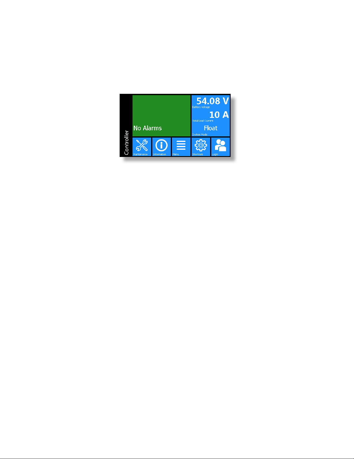
16
Figure 6 — LCD Color Touchscreen Display
• USB: dual ports on both the front and rear of the controller for upgrades and file management via a standard
USB flash drive.
• CAN: dual independent CAN bus ports for communication with the Cordex and AMPS family of products, which
allows for a greater number of devices.
• Real-time clock with field replaceable lithium battery: allows for timestamps on alarms and events.
• System fail alarm/relay: which activates when there is a major internal failure. During such a condition the unit at-
tempts to reset.

17
9400000-J0 Rev E
5. Inspection
5.1 Packing Materials
All Alpha products are shipped in rugged, double walled boxes and suspended via solid inserts to minimize shock
that may occur during transportation. Packaging assemblies and methods are tested to International Safe Transit
Association standards.
Rectifiers and batteries are shipped on individual pallets and are packaged according to the manufacturer’s guide-
lines.
5.1.1 Returns for Service
Save the original shipping container. If the product needs to be returned for service, it should be packaged in its
original shipping container. If the original container is unavailable, make sure that the product is packed with at least
three inches of shock-absorbing material to prevent shipping damage.
NOTE:
Alpha Technologies is not responsible for damage caused by improper packaging of
returned products.
5.2 Check for Damage
Before unpacking the product, note any damage to the shipping container. Unpack the product and inspect the
exterior for damage. If any damage is observed, contact the carrier immediately.
Continue the inspection for any internal damage. In the unlikely event of internal damage, inform the carrier and con-
tact Alpha Technologies for advice on the impact of any damage.
5.3 General Receipt of Shipment
The inventory included with your shipment depends on the options you have ordered. The options are clearly
marked on the shipping container labels and bill of materials.
5.3.1 Shelves
Consult the packing slip and power system bill of materials to verify that you have the correct number of shelves per
your order.
5.3.2 Rectifiers (Purchased Separately)
Consult the packing slip to verify that you have received the correct number of rectifiers per your order.
5.3.3 Miscellaneous Small Parts
Review the packing slip and bill of materials to determine the part number of the “configuration kits” included with
your system.
Review the bill of materials to verify that all the small parts are included.

9400000-J0 Rev E
18
6. Installation
The equipment is suitable for installation in Network Telecommunication Facilities.
WARNING!
This system is designed to be installed in a restricted access location that is inacces-
sible to the general public.
The following procedure is written for qualified personnel to install this product in a clean and dry environment. For
the battery installation, refer primarily to the manufacturer’s manual.
6.1 Safety Precautions
Refer to the Safety section near the front of this manual before beginning this installation.
6.2 Tools Required
Various insulated tools are essential for the installation. Use this list as a guide:
• Battery lifting apparatus if required
• Electric drill with hammer action, 1/2" capacity
• Various crimping tools and dies to match lugs used in installation
• Load bank of sufficient capacity to load largest rectifier to its current limit
• Digital voltmeter equipped with test leads
• Cable cutters
• Torque wrench: 1/4" drive, 0 - 150 in-lb
• Torque wrench: 3/8" drive, 0 - 100 ft-lb
• Insulating canvases as required (2' x 2', 1' x 1', 3' x 3', etc.)
• Various insulated hand tools including:
- Combination wrenches - Ratchet and socket set
- Various screwdrivers. - Electricians knife
• Battery safety spill kit required for wet cells only:
- Protective clothing - Face shields
- Gloves - Baking soda
- Eye wash equipment
• Cutters and wire strippers (#14 to #22 AWG) [2.5 to 0.34 mm²]
This manual suits for next models
3
Table of contents
Other EnerSys Power Supply manuals

EnerSys
EnerSys alpha LPS36 Quick start guide

EnerSys
EnerSys alpha APX3 Series User manual

EnerSys
EnerSys Alpha Broadband UPS User manual

EnerSys
EnerSys Alpha FMPS FTTP User manual

EnerSys
EnerSys alpha APX3-G Series User manual

EnerSys
EnerSys alpha CXPS-E3 User manual

EnerSys
EnerSys Alpha XRT-TPPL User manual


