PullRite Super Lite 2600 User manual

OWNER’S MANUAL
#2600 (20K) Single Point Attachment Fifth Wheel Hitch
Gross Trailer Weight (Maximum) 20,000 lbs.
Vertical Load Weight (Max. Pin Weight) 5,000 lbs.
The following instructions provide valuable information regarding the function and proper use of the SuperLite Fifth Wheel Towing System.
.
YOU MUST COMPLETELY READ THE INSTRUCTIONS WITHINTHIS MANUAL, PRIOR TO OPERATING THE HITCH TO PREVENT UNNECESSARY DAMAGE
TO THE HITCH, VEHICLE, ORTRAILER.

SYSTEM WEIGHT RATING VS. COMPONENT WEIGHT RATING..............................................................3
CAB CLEARANCE........................................................................................................................................3
GM TRUCK SUPPORT INFO.....................................................................................................................4,5
KNG PIN ADAPTER BALL & COUPLER TUBE..........................................................................................6
BED SAVER RAILS......................................................................................................................................6
ANNUAL MAINTANANCE............................................................................................................................6
HEIGHT ADJUSTMENT................................................................................................................................7
KING PIN ADAPTER INSTALLATION..........................................................................................................8
GOOSENECK RECEIVER INSTALLATION.................................................................................................9
ATTACHING THE HITCH............................................................................................................................10
HITCHING....................................................................................................................................................11
SAFETY CHECKS PRIOR TO TOWING.....................................................................................................11
UNHITCHING..............................................................................................................................................12
CHALLENGE VS SOLUTION.....................................................................................................................12
ROTA-FLEX PINBOX RUBBER ISOLATOR..............................................................................................13
RELATED ACCESSORIES.........................................................................................................................14
TORQUE TABLE.........................................................................................................................................15
#2600 EXPLODED VIEW............................................................................................................................16
#2600 PARTS LIST......................................................................................................................................17
TABLE OF CONTENTS

3
SYSTEM WEIGHT RATING VS. COMPONENT WEIGHT RATING..............................................................3
CAB CLEARANCE........................................................................................................................................3
GM TRUCK SUPPORT INFO.....................................................................................................................4,5
KNG PIN ADAPTER BALL & COUPLER TUBE..........................................................................................6
BED SAVER RAILS......................................................................................................................................6
ANNUAL MAINTANANCE............................................................................................................................6
HEIGHT ADJUSTMENT................................................................................................................................7
KING PIN ADAPTER INSTALLATION..........................................................................................................8
GOOSENECK RECEIVER INSTALLATION.................................................................................................9
ATTACHING THE HITCH............................................................................................................................10
HITCHING....................................................................................................................................................11
SAFETY CHECKS PRIOR TO TOWING.....................................................................................................11
UNHITCHING..............................................................................................................................................12
CHALLENGE VS SOLUTION.....................................................................................................................12
ROTA-FLEX PINBOX RUBBER ISOLATOR..............................................................................................13
RELATED ACCESSORIES.........................................................................................................................14
TORQUE TABLE.........................................................................................................................................15
#2600 EXPLODED VIEW............................................................................................................................16
#2600 PARTS LIST......................................................................................................................................17
YEAR LIMITED WARRANTY.........................................................................................................................i
PRODUCT REGISTRATION.........................................................................................................................ii
A towing system includes each vehicle and component involved in towing. Each item in your towing system has a capacity
or weight rating.Your trailer has a Gross Vehicle Weight Rating or GVWR. Your truck has a towing capacity, a payload
above, the GVWR of your trailer for you to tow safely. In addition, if your truck can tow larger loads (has a larger capacity)
than the rating of your hitch, your system is only safe to tow loads at the lower rating, that of the hitch.
could be lower depending on the components involved. The lowest rating of any one component in the system becomes
the rating of the entire system. If your ball is rated to 18,000 lbs., and your hitch is rated at 24,000 lbs., the weight rating
of the entire system will not be above 18,000 lbs. Other components in the system could lower the actual system rating
further.
It is the end users responsibility to ensure a safe towing experience. To this end, It is your responsibility to ensure that
involved.
SYSTEM WEIGHT RATING vs. COMPONENT WEIGHT RATING
CAB CLEARANCE
If you are towing with a short bed truck, you may be aware that adequate cab clearance is needed for sharp angle turns
and damage to the truck cab could occur if the clearance is not calculated correctly.
This formula is a guide for checking clearance: (cab to axle) - (half of trailer width) = cab clearance
Here are a few examples:
BED LENGTH CAB-TO-AXLE DIST. CAB-TO-TRAILER CLEARANCE
8 ft. 56” 56” - 48” = 8” of cab clearance
6 ft. 40” 40” - 48” = - 8” negative cab clearance
5-1/2 ft. 28-1/4” 28.25” - 48” = -19.75 negative cab clearance
As you can see, an 8’ bed truck provides more clearance than needed, whereas a 6’ bed truck does not allow for a full
tighter turns.The 5-1/2’ bed truck provides even less cab clearance.
If towing with a truck bed that is 6 ft. or less, you must take into consideration that most gooseneck ball installations are
located ahead of the truck axle, which in turn reduces the trailer to cab clearance. This hitch will provide a minimum of 3
slightly behind the truck’s rear axle.
While the #2600 can be used with these shorter bed trucks, keep in mind that PullRite only recommends the use of a
slider type hitch for any towing application without 100% cab clearance.
4
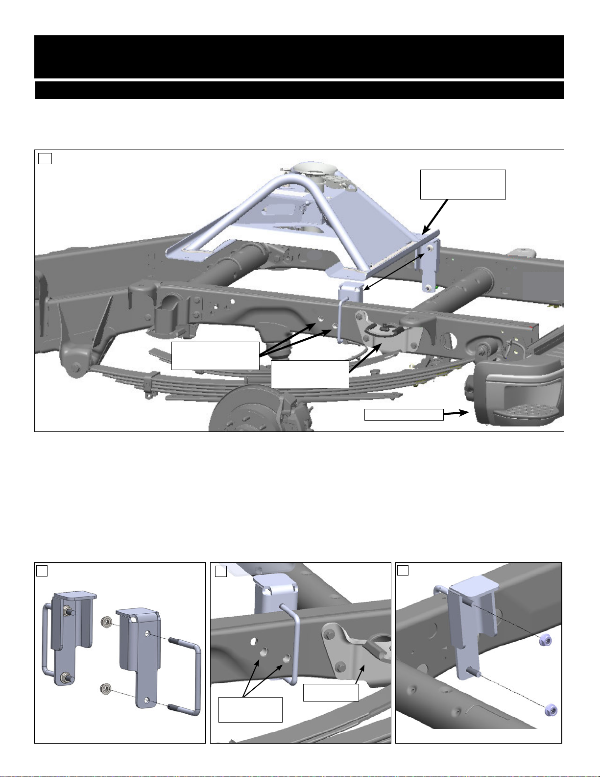
GM TRUCK SUPPORT BRACKET KIT #2616
This bracket kit fastens under the GM truck bed to the frame where the SuperLite’s rearward rail sits.This helps support
the hitch and prevents wear to the truck bed.The bracket kit is a no-drill install that clamps around the truck frame on both
sides.
REQUIRED WHEN USING THE #2600 SUPERLITE IN GM TRUCKS FROM YEARS 2010 - PRESENT
U-BOLT
GM TRUCK BED CUTAWAY VIEW
(DRIVER’S SIDE)
U-BOLT
BRACKET
Note: The brackets are identical and can be used for either side.
1. Place U-bolt around the truck frame at the point between the OE
and slide on brackets inside truck frame. If OE bracket is present, your truck is equipted with the OE prep package.
For this you will need the PullRite OE Puck Plug kit #2620
REVERSE VIEW
FRAME
REARWARD
BED SAVER RAIL
C
B
A
OVERLOAD
OE BRACKET
REAR BUMPER
OVERLOAD
OE BRACKET
(DRIVER SIDE)
#2616
KIT
D

5
GM OE PUCK PLUG KIT #2620
SUPERLITE 2600 SUPPORT FOR GM TRUCKS WITH OE PREP PACKAGE
If your GM truck features the OE prep package for towing, use the GM OE Puck Plug kit (part #2620) in place of the
Saver rails.
PLACE PUCK PLUGS
GM OE PUCK PLUGS
GM TRUCK BED
BALL
PUCK
GM OE PUCK PLUG
:
- First, remove the (4) OE Puck Covers.
- Repeat with the other three plugs. Make sure all (4) plugs are set into each puck location.
The Pullrite 2600 hitch is ready to Install.
TOP
6
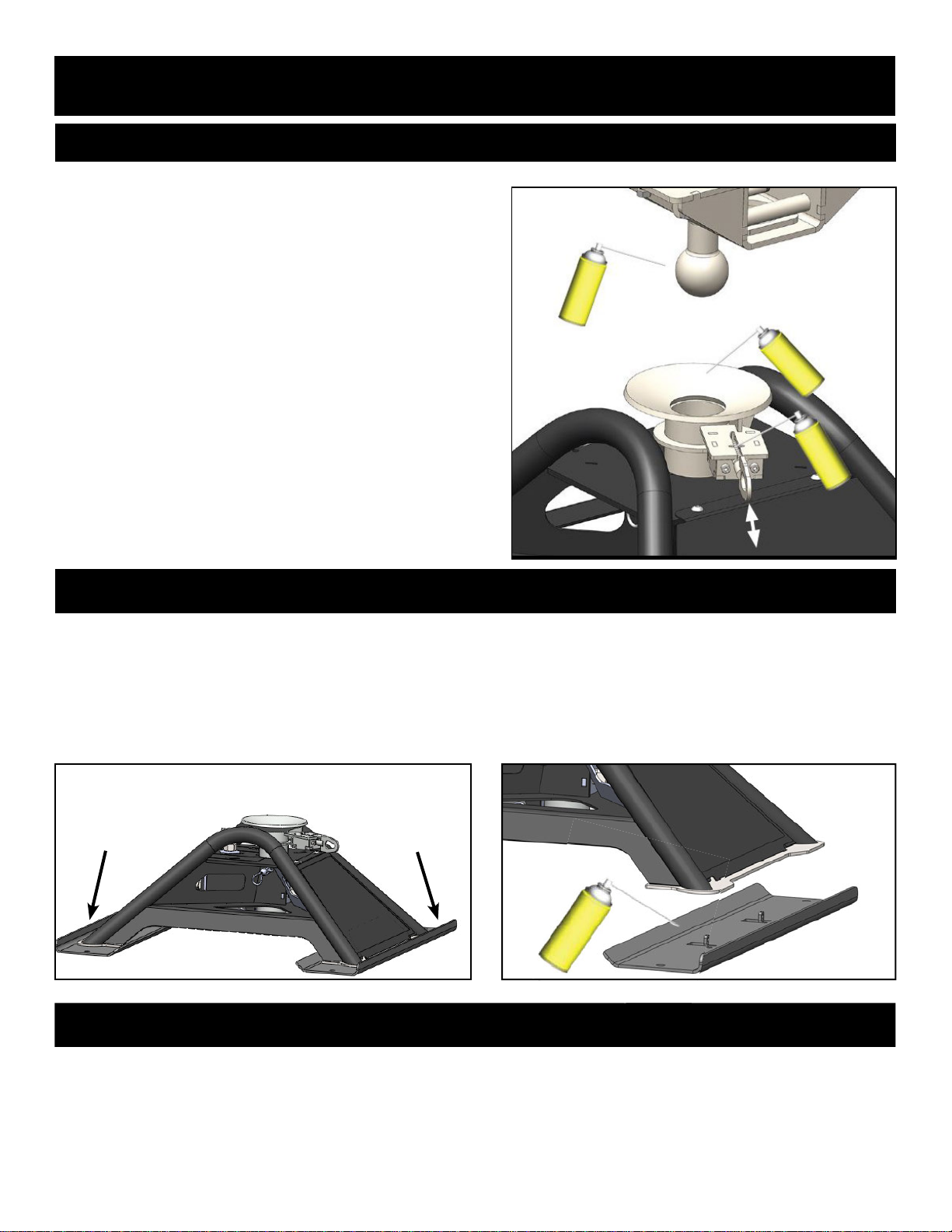
LUBRICATION
DO NOT OPERATE HITCH UNTIL YOU READ THIS SECTION!
KING PIN ADAPTER BALL & COUPLER TUBE
BED SAVER RAILS
ANNUAL MAINTENANCE
Inspect all hitch hardware to verify that it is securely fastened. Inspect set screws and bolts for tightness and general
condition. When storing your SuperLite hitch, you should be sure that the coupler and hitch parts are lubricated with WD-
40, or dry lube like our own Slip Plate brand spray (#33040301). Use wet lube for wear areas such as the contact area
prevent accumulation of dirt, grime, and rust.
The King Pin Adapter Ball and Remote Latch System must be
lubricated before each trip or as needed. PullRite recommends
using a dry graphite spray to prevent the attraction of dust and
debris. A light wet lubricant such as WD-40 can also be used,
but the two types of lubricants should not be used together.
Be sure the Coupler Tube is free of any obstructions prior to
lubrication and before each use. Spray both the Tube and
Funnel areas to aid in hitching up.
When lubricating the Remote Latch System using a dry graphite
spray, place the latch system in both closed and open positions
the Release Handle repeatedly between the open and closed
positions, so the lubricant is evenly spread among the moving
parts.
Be sure the King Pin Adapter Ball is clean and free from rust. A
light coating of lubricant should be used before each trip or as
needed.
The Bed Saver Rails connect to the bottom of the hitch and are coated with bed liner type material to protect your truck
bed against scratches, paint wear, and galvanic corrosion when in contact with aluminum truck beds. These Bed Saver
Rails are engineered to distribute the weight of the load more evenly, also to keep the hitch from laterally rotating out of its
intended position.
Because these Bed Saver Rails absorb the vibration movement of the hitch, use a spray like WD-40 for the areas on top
where the Hitch Base makes contact. An alternative to lube would be to use our Plastic Slide Kit. See accessories on
page 13 for details.
BED SAVER RAILS

7
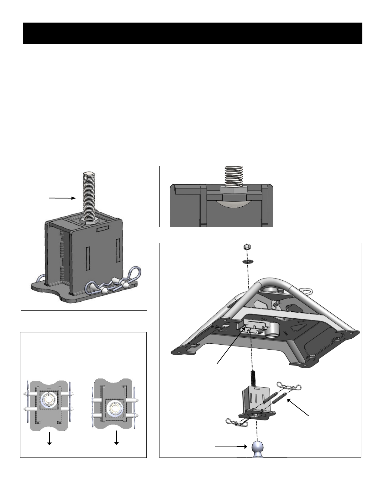
HEIGHT ADJUSTMENT
The #2600 SuperLite is height adjustable and can be set at three positions. Refer to the illustration below and the “#2600
remove the bolts - just back out about two complete turns or until the coupler is loose in the base.
2. Remove the bent hitch pin and clip and adjust to the desired height.
3. Re-pin and clip.
Over-tightening these set
screws could cause damage to the base. Always torque properly.
Heights shown here
are installed heights. To
obtain the correct height
needed for towing, choose
the corresponding hole in
the coupler Tube.
The installed heights
listed here are measured
from the base of the hitch
to the top of the King Pin
Adapter (bottom of your
trailer’s pin box skidplate)
once properly installed.
NOTE: Two of the three
set screws are located
behind the PullRite
logo plate

8
1. Verify that the king pin is clean and free
of burrs before installing the King Pin
Adapter. Remove any burrs with a
2. Slide the King Pin Adapter over the king
pin and install one Adapter Plate Bolt
through the smaller cross hole nearest
3. Install the Adapter Bolt Reinforcement
in the Adapter Plate, then the remaining
Adapter Plate Bolt and Flat Washer
through this tube. Install nut and snug by hand.
the position you would like installed; placing the hitch ball ahead of the king pin will add additional cab clearance
during tight turns, but does not guarantee total cab clearance for short bed trucks. Likewise, placing the ball behind
the king pin will reduce the trailer-to-cab clearance. Orient the King Pin Adapter appropriately and make sure it’s
aligned parallel with the king pin box.
the King Pin Adapter and the king pin box’s skid plate may be uneven due to several conditions, e.g., concave or
convex skid plate or a skewed king pin.
7. Torque both Adapter Plate Bolts installed in Steps 2 & 3 to 75 ft. lbs.
should not be necessary most of the time.
KING PIN ADAPTER INSTALLATION
NOTE: It is important that you check the tightness of the adapter set screws often, as they can begin to work themselves
loose over a period of time from the normal stresses of towing.
A6 A5 A4 A1
A2
A3
TOP ANGLE
9
GOOSENECK RECEIVER INSTALLATION
The Gooseneck Receiver is the box that fastens to the original equipment (prep kit) gooseneck ball or aftermarket
1. Place Gooseneck Receiver over the ball in the truck bed as shown below. Connect with provided clevis pins
through the (2) holes in the bottom of the Gooseneck Receiver. Then fasten hairpin clips through clevis pins on both
sides.
ensure the hitch is placed in the correct position.
GOOSENECK RECEIVER
ABOVE VIEW
FORWARD REARWARD
RECEIVER
TO TAILGATE
BOLT
VIEW OF THE
RECEIVER
10
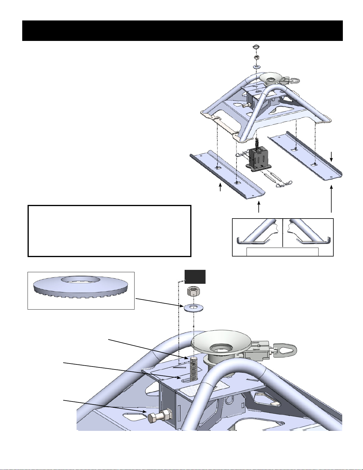
ATTACHING THE HITCH
OVAL SLOT
SET SCREW
COUPLER TUBE
BED SAVER RAILS
90°
1. Set the hitch over the Gooseneck Receiver with the PullRite
logo plate facing the truck tailgate. Make sure that the Draw
Down Bolt from the Gooseneck Receiver extends up through
the oval slot in the top of the hitch near the Coupler Tube.
Slide the Bed Saver Rails in place under hitch feet (90° bend
facing outward as seen in diagram at right), and attach
with clips. Once the hitch is seated, the next step is to fasten
the hitch down to the truck bed.
2. Place the Conical Tooth Washer (teeth down) over the
Draw Down Bolt to the hitch, and then thread on the
foot pounds. As an extra measure of security, insert the
provided lynch pin through the hole in top of Draw Down Bolt
above the nut and snap ring over into the lock position.
3.
L
ocate the set screw and jam nut on the front of the hitch
facing the truck cab.Tighten the set screw to 45 foot pounds
using a torque wrench, and then snug tighten the jam nut.
Make sure hitch is tight against the truck bed.
Warning: The Draw Down Bolt and fasteners are the only
bolt holding your hitch in place, care should be given to make
sure that each time you install your hitch, you have inspected
each fastening element for wear, corrosion, crossed threads
or any unusual appearance. you should also check the torque
of the Draw Down Nut between each use.
REAR
11
HITCHING
a person is between the vehicle and trailer.
1. Verify that the Latch Handle is pulled outward and rotated (left
or right) into the latched open position (right). Damage could result
should you attempt to hook up with the latch pin in the closed position.
2. Lower the trailer landing gear high enough to raise the ball above the
top of the coupler funnel.
3. After lowering your truck tail gate, back the truck under the kingpin
adapter to orient the ball above the funnel coupler (make sure there
is space to completely back your truck into hitching position with the
tailgate down). It is not necessary to be completely centered over
the coupler, as long as the center of the ball is inside the diameter of
trailer jacks are retracted.
4. Lower the trailer landing gear so the ball drops into the hitch coupler.
The ball must be fully seated in the coupler to allow the latch
mechanism to close properly.
5. Once the weight of the trailer is supported by the tow vehicle, use the
latch handle to rotate the latch pin so that it retracts into the locked position. Do not forget this step.
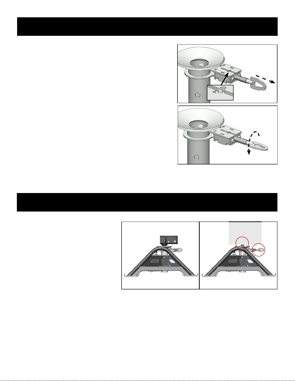
1. Prior to towing, it is imperative to know if are
hooked up and the lock pin is engaged:
• First, check the height of the King Pin
Adapter; if seated properly below the Latch
Pin, it will sit at the correct height (top left). If
it’s sitting higher than it should, you’ve either
not lowered your trailer enough, or it’s sitting
on top of the Latch Pin inside the Coupler
Tube.
• Second, check the Latch Handle.
If it is pulled outward in the open position,
you’ve not secured the Lock Pin over the ball of the King PinAdapter (top right).
2. Raise the trailer jack base plates just above the ground, lock your trailer brakes, then pull the tow vehicle slowly forward
putting a strain on the trailer.
3. When you are assured that the trailer is safely hooked up, raise your trailer jacks into their fully retracted position.
FAILURE TO PERFORM THESE SAFETY CHECKS MAY RESULT IN DAMAGES TO TRUCK AND TRAILER.
SAFETY CHECKS PRIOR TO TOWING
INCORRECTCORRECT
LATCH HANDLE PULLED
OUTWARD, PIN CENERED
TO SLOT OPENING
LATCH HANDLE ROTATED,
PIN TURNED INTO SLOT
OPENING
LATCH
HANDLE
PIN

12
WARNING:
1. Once you have the trailer located and are ready to unhitch, block the trailer wheels so it will not roll back or forward.
2. Pull the Latch Handle towards the rear of the vehicle and rotate either clockwise or counterclockwise into the
adapter ball from the tube.
3. Extend the trailer jacks until the ball is fully removed from the Coupler Tube and above the top of the coupler
funnel.
4. After lowering the truck’s tailgate, disconnect the trailer’s electrical cord and break-away switch cable, then pull
forward.
is latched before moving the trailer.
UNHITCHING
CHALLENGE VS. SOLUTION
CHALLENGE SOLUTION
Cannot open the Latch Pin. Should only be restricted if trailer is applying pressure to the pin.
Raise trailer jacks to relieve ball pressure against pin.
pin.
(particularly near the junction of the king pin and skid plate),
bent, skewed, or king pins that are too long or too short can
(800) 443-2307 and we will give you suggestions what you can do
to correct these problems.
Trailer overhang is hitting the truck bed rails when
the trailer and truck are at sharp angles. Raise or lower the hitch coupler height and/or lower the king pin
and bottom of the trailer.
operate. Spray the locking mechanism with WD-40. Work the handle until
it slides freely. If the problem persists, you may need to degrease
and re-lube all working parts.
I need to have a professional evaluate my
SuperLite 2600. Contact PullRite’s Customer Service Dept. at (800) 443-2307.
Your needs will be assessed and resolved by PullRite or you will

13
ROTA-FLEX PINBOX RUBBER ISOLATOR
In the case that you use a Rota-Flex pinbox or similar design, the rubber block inside the pinbox has a tendency to work
its way out of place while towing with the SuperLite hitch. PullRite’s Pinbox Rubber Isolator (Part # 4446) restricts and
keeps the rubber block in place.
I
#4446
ISOLATOR
1. Install tubes. Place one tube in front of the pivot jaw, centered side to
the pinbox and skid plate at the rear of the pivot jaw. Align the pre-
drilled holes in both tubes, front to back.
roughly the middle of the threaded rod. Place (5) shims onto the rod
3. Insert threaded rod end into the hole on the inside of the back tube,
Repeat this step and step # 2 with the threaded rod for the opposite
4. Rotate the shims so that they are resting on the skid plate between
end with two open end wrenches until they are snug against the
tubes. Repeat on other end and opposite side.
5. Inspect to make sure unit is tight overall.
A properly Installed kit should be tightly braced and will look like
{g. D} and {g. E) below.
(SIDE)
AN UPGRADE VERSION OF THIS RUBBER ISOLATOR (PART #4447) IS AVAILABLE, SEE NEXT PAGE FOR THESE & OTHER SUPERLITE ACCESSORIES.
SHIMS
PLACE TUBES
A
C
D
E
B
1/2-13
THREADED
ROD
14
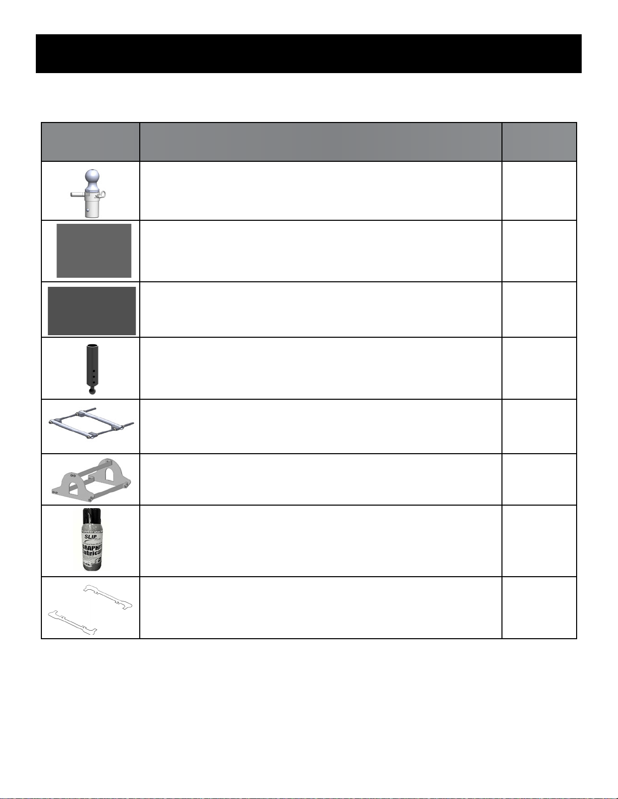
RELATED ACCESSORIES
IMAGE DESCRIPTION PART #
30K OE Series Gooseneck Ball
-Fits truck’s factory-equipped Tow Prep Package.
-American made with patented TwistLock technology.
4436
30K OE Series Gooseneck Ball w/ Plate
-Fits truck’s factory-equipped Tow Prep Package.
-American made with patented TwistLock technology.
4437
30K OE Series Gooseneck Ball Chain Plate
A companion piece for the OE Series Gooseneck Ball. 4438
20K SuperLite GooseneckTrailer Adapter
Easy to install adapter for a horse trailer, or any gooseneck-type trailer 4443
Pinbox Rubber Isolator
Keeps rubber on Rota-Flex pinboxes from working its way out of place
when towing with the #2600 4446
Pinbox Rubber Isolator
A stronger and easier to install upgrade of the #4446 4447
SlipPlate Dry Graphite Lubricant Spray
Case of 12 - 12 ounce cans
(Single 12 ounce can - #33040301)
330403
Lube Plate Kit for Bed Saver Rails
Eliminates the need for lubricant where the rails make contact with the hitch 2618
available now through PullRite dealers.

15
TORQUE TABLE
HARDWARE SIZE TORQUE SPECS
SCREWS
5FT. LBS -
FACTORYASSEMBLED
ADAPTER PLATE SET
SCREWS
20 FT. LBS - MUST BE TORQUED
BEFORE
ADAPTER PLATE BOLTS
ADAPTER PLATE BOLTS 75 FT. LBS - TORQUE AFTER ADAPTER
PLATE SET SCREWS
COUPLER TUBE SET
SCREWS 45 FT. LBS
60 FT. LBS
RECEIVER
SET SCREW 45 FT. LBS

16
#2600 EXPLODED VIEW
B
C
B1 B2 B3
D
G
F
C1
C6
C5
C4
E1 E2
E3
E4
E
C5
C3
A6
A
A5
A4
A1
C7
A2
A3
C8 C9
C2

#2600 PARTS LIST
ITEM .QTY
A 2403 1
BCOUPLER TUBE ASSEMBLY 2402 1
C BASE HITCH 2601 1
D 2405 1
ADAPTER PLATE HARDWARE KIT
A1 98150201 1
A2 98150168 1
A3 ADAPTER PLATE SET SCREWS 98010222 1
A4 ADAPTER 24030201 1
A5 FLAT WASHER 98250147 1
A6 ADAPTER PLATE BOLT 98010203 1
LATCH PIN ASSEMBLY
B1 240205 1
B2 24020601 1
B3 98410236 2
BASE HARDWARE KIT #260204
C1 98010216 1
C2 98150176 1 5/8-11
C3 010019 1 5/8
C4 COUPLER TUBE CLIP 98410143 1
C5 COUPLER TUBE SET SCREW 98010231 3
C6 98150176 3 5/8-11
C7 98200173 1
C8 98150131 1
C9 98410525 1
GOOSENECK RECEIEVER AND HARDWARE KIT
E 260202 1
E1 26020206 2 5/8
E2 CLIPS 98410143 4
E3 98410526 1
E4 26020207 1
FRONT PLATE
F 260203 1
BASE RAILS
GBED SAVER RAILS 26030101 2
Discover other trailer hitches and towing on our website.
Table of contents
Other PullRite Automobile Accessories manuals


Popular Automobile Accessories manuals by other brands

TAC
TAC TB-D08 manual

Yakima
Yakima K1222 instructions

Curt Manufacturing
Curt Manufacturing CM18153 installation instructions

Whelen Engineering Company
Whelen Engineering Company LFL Liberty Mini Edge installation guide

Kuda-Phonebase
Kuda-Phonebase 043270 Installation instruction

Roadmaster
Roadmaster 156-25 installation instructions


Safe Fleet
Safe Fleet PRIME DESIGN ACX Assembly instructions

Thule
Thule Canoe Carrier 579xt installation guide

STO N SHO
STO N SHO SNS 59 Installation procedures

Bracketron
Bracketron Multi Vehicle Mount MVM-15-05 installation manual

POOL-LINE
POOL-LINE 110050 Assembly instructions

Jotto Desk
Jotto Desk 425-5595 quick start guide