PullRite OE Series User manual

YOU MUST COMPLETELY READ THE INSTRUCTIONS WITHIN THIS MANUAL, PRIOR TO OPERATING
THE HITCH TO PREVENT UNNECESSARY DAMAGE TO THE HITCH, VEHICLE, OR TRAILER.
ALL PULLRITE HITCHES TESTED TO SAE J2638 STANDARDS • MADE IN THE USA
For more information, please call PullRite at (800) 443-2307.
#4500 (24K) OE Series SuperGlide
Gross Trailer Weight (Maximum)...............................24,000 lbs
Vertical Load Weight (Max.Pin Weight).......................5,000 lbs
The following instructions provide valuable information regarding the function
and proper use of the OE Series SuperGlide Fifth Wheel Towing System.
Fits 2020 and newer GM trucks w/ OE Prep Package
OWNER’S MANUAL

SYSTEM WEIGHT RATING vS. COMPONENT WEIGHT RATING..............................................................3
HOW DOES SUPERGLIDE WORK?............................................................................................................4
CAUTION AND TESTING CLEARANCE......................................................................................................5
MAINTENANCE.............................................................................................................................................6
LUBRICATION.............................................................................................................................................6,7
ATTACH HANDLE TO HEAD PLATE............................................................................................................8
FIFTH WHEEL PLATE OPERATION.........................................................................................................9,10
HITCH INSTALLATION.................................................................................................................................11
BUILD THE POST ASSEMBLY....................................................................................................................12
MOUNTING POST INSTALLATION.............................................................................................................13
MOUNTING POST ADJUSTMENT...............................................................................................................14
HITCHING.....................................................................................................................................................15
SAFETY CHECKS & UNHITCHING.............................................................................................................16
ADJUSTING THE CAM ARM ASSEMBLY...................................................................................................17
CHALLENGE vS SOLUTION.......................................................................................................................18
FREQUENTLY ASKED QUESTIONS...........................................................................................................19
EXPLODED vIEW.........................................................................................................................................20
PARTS LIST #4500.......................................................................................................................................21
LIMITED WARRANTY.....................................................................................................................................i
PRODUCT REGISTRATION..........................................................................................................................ii
TABLE OF CONTENTS

3
2.09.21.RH.rev A
SYSTEM WEIGHT RATING vS. COMPONENT WEIGHT RATING..............................................................3
HOW DOES SUPERGLIDE WORK?............................................................................................................4
CAUTION AND TESTING CLEARANCE......................................................................................................5
MAINTENANCE.............................................................................................................................................6
LUBRICATION.............................................................................................................................................6,7
ATTACH HANDLE TO HEAD PLATE............................................................................................................8
FIFTH WHEEL PLATE OPERATION.........................................................................................................9,10
HITCH INSTALLATION.................................................................................................................................11
BUILD THE POST ASSEMBLY....................................................................................................................12
MOUNTING POST INSTALLATION.............................................................................................................13
MOUNTING POST ADJUSTMENT...............................................................................................................14
HITCHING.....................................................................................................................................................15
SAFETY CHECKS & UNHITCHING.............................................................................................................16
ADJUSTING THE CAM ARM ASSEMBLY...................................................................................................17
CHALLENGE vS SOLUTION.......................................................................................................................18
FREQUENTLY ASKED QUESTIONS...........................................................................................................19
EXPLODED vIEW.........................................................................................................................................20
PARTS LIST #4500.......................................................................................................................................21
LIMITED WARRANTY.....................................................................................................................................i
PRODUCT REGISTRATION..........................................................................................................................ii
A towing system includes each vehicle and component involved in towing. Each item in your towing system has a capacity
or weight rating. Your trailer has a Gross Vehicle Weight Rating or GVWR. Your truck has a towing capacity, a payload
capacity, and possibly more. In addition, your fth wheel hitch has a weight rating. This weight rating must be at, or
above, the GVWR of your trailer for you to tow safely. In addition, if your truck can tow larger loads (has a larger capacity)
than the rating of your hitch, your system is only safe to tow loads at the lower rating, that of the hitch.
Your gooseneck ball will also have a weight rating, just like your fth wheel hitch. Many times, these ratings are designed
to match, but this is not always the case. Your gooseneck ball may be higher rated than your fth wheel hitch, but it also
could be lower depending on the components involved. The lowest rating of any one component in the system becomes
the rating of the entire system. If your ball is rated to 18,000 lbs., and your hitch is rated at 24,000 lbs., the weight rating
of the entire system will not be above 18,000 lbs. Other components in the system could lower the actual system rating
further.
It is the end users responsibility to ensure a safe towing experience. To this end, it is your responsibility to ensure that the
truck, trailer, hitching components, and all other items involved are rated or have a capacity sucient for the loads
involved.
SYSTEM WEIGHT RATING vs. COMPONENT WEIGHT RATING

42.09.21.RH.rev A
HOW DOES SUPERGLIDE WORK?
The SuperGlide is an automatically sliding fth wheel hitch based on a mechanical, cam action. Other sliding hitches
on the market today require you to get in and out of the vehicle multiple times before and after a turn, throwing levers to
allow it to move back and forth. The cam action of the SuperGlide hitch is truly automatic. When installed in your short
bed truck and used in conjunction with our Capture Plate, the SuperGlide “glides” along the Way Tubes with ease, making
turns automatically, without you having to ever get out of your vehicle. Here’s how it works:
Equipping your trailer’s king pin box with one of our Capture Plates (required for the hitch to function properly and sold
separately), restricts the king pin on your trailer from turning in the fth wheel plate on the SuperGlide. Once the truck
begins to make a turn, the “captured” fth wheel plate forces the large roller of the turntable cam arm assembly to rotate
and roll along the path of the cam slot to begin the turn. This action pulls the plate and turntable assembly, with trailer in
tow, away from the cab of your truck. The more you turn, the more it moves back.
It is important to note that the width of the trailer and
the location of the king pin in relation to the “nose”, or
leading edge of the trailer, is critical in determining if
your truck and trailer are compatible to be used with a
SuperGlide. Short bed trucks have only so much room
from cab-to-axle; if your king pin is located too far under
the nose of the trailer, the cam action of the SuperGlide
may not move the trailer back fast enough to allow the
necessary clearance.
Another important point in the use and maintenance
of your SuperGlide is the need to lubricate the moving
parts. SuperGlide hitches manufactured after November
2009 are equipped with Low Friction Polymer Wear
Plates and require a light oil application to enhance the
movement of the Turntable Cam Arm Assembly on the
Way Tubes.
The #4500 SuperGlide is equipped with Low Friction Polymer Wear Plates on the Turntable/Cam Arm Assembly to
eliminate the need for constant lubrication between the metals of the Turntable and the Way Tubes. It is important to
protect the Wear Plates from possible damage by keeping the Way Tubes free from rust and corrosion by applying a
coating of light oil on the Tubes and the Turntable Shaft.
BEFORE OPERATING YOUR SUPERGLIDE HITCH,
YOU MUST READ THE “LUBRICATION” SECTION.
IF YOU HAVE ANY QUESTIONS REGARDING
LUBRICATION OR HOW THE SUPERGLIDE
FUNCTIONS, PLEASE CONTACT OUR CUSTOMER
SERVICE DEPARTMENT AT (800) 443-2307 BEFORE
USING YOUR SUPERGLIDE.
FIFTH WHEEL PLATE
CUTAWAY VIEW
WAY TUBE
ROLLER
CAM ARM
TURNTABLE
WEDGE
CAPTURE PLATE

5
2.09.21.RH.rev A
CAUTION
TESTING CLEARANCE
When you are assured your trailer is safely hooked up, pull forward and slowly start to turn. Make sure that someone is
outside watching the distance between the cab and the trailer. The distance between the cab and trailer should be greater
than two inches at all points of the turn. Specically watch the distance when the corner of the trailer is closest to the cab
and also when nearing a 90 degree turn. The minimum two inches of clearance is needed for normal driving conditions.
The practice of testing clearance will let you know how much clearance you actually have should you encounter adverse
road conditions.
EXAMPLE: It is possible for the trailer to hit the cab when turning through a dip where the corner of the trailer is closest to
the cab or when nearing a 90° turn.
• The width of the trailer and the location of the king pin in relation to
the “nose” (Dimension A), or leading edge of the trailer, is critical
indetermining if your truck and trailer are compatible to be used witha
SuperGlide. If your king pin is located too far under the nose of the
trailer, the cam action of the SuperGlide may not move the trailer back
fast enough to allow the necessary clearance. Call PullRite Customer
Service at (800) 443-2307 with trailer width, make and year of truck,
and the distance of the king pin from the leading edge of the trailer
(Dimension A).
• Using a trailer that has a long rear slope to the king pin box hangar,
“B”, may cause damage to the king pin box or the inside edge of the
truck bed. Dimension “B” must be less than one half the width of the
inside top edges of the bed during turns for proper clearance.
• The SuperGlide hitch is equipped with a side-to-side pivot feature.
There should be a minimum of 6” between the truck bed rails and
the under side of the trailer for side tilt clearance. It is the customers
responsibility to adjust the trailer king pin box for the appropriate
amount of clearance depending on the terrain being traveled (example: some State Parks are sloped and unpaved;
some driveways are steeply angled). If after-market bed covers are added, care must be taken to allow for additional
clearance.
• The SuperGlide hitch is designed to allow you to make a 90° turn. Please use extreme caution when turning this far.
In addition to putting stress on the wheels and axles of your trailer.
IMPORTANT: Please be aware that if you make a turn greater than 90° the trailer will contact your truck and you WILL
damage various parts of the hitch which will NOT be covered under the manufacturers warranty.
• Position your brake cable so the slack in the cable will not be allowed to catch on the hitch during turns or lodge in
the cam mechanism. Failure to modify its length may cause the cable to catch on protruding parts of the hitch which
could activate the trailer brake, causing damage to the truck, trailer or hitch. Resulting damages will not be covered by
warranty.
• Position or coil any slack in your 7-way electrical cable out of the way of your moving hitch. It is preferred that the plug
and cabling remain isolated rearward of the hitch (nearest the tailgate) to prevent damage. Make slow test turns while
observing the 7-way cable until you are satised that it will not become caught in the hitch mechanism.
• Anything carried in the bed of your truck during towing will need to be well secured. Remove any foreign debris that
might move around in the bed and contact the hitch. This will help to ensure that nothing will get caught in or jam
the movement of the cam which can cause damage to the hitch.

62.09.21.RH.rev A
MAINTENANCE
HITCH LUBRICATION
LUBRICATION
DO NOT OPERATE HITCH UNTIL YOU READ THIS SECTION!
The SuperGlide hitch was designed to allow the Turntable Cam Arm Assembly to “glide” along two metal tubes, called
the Way Tubes. Since it’s release in 1998, we have made several advancements in the design, strength, and durability of
these components. The Turntable Cam Arm Assembly is equipped with innovative Low Friction Polymer Wear Plates. It is
imperative that you read each of the following sections so you can learn how to care for your hitch properly.
Inspect all mounting bracket and hitch hardware, that it is securely fastened. The Fifth Wheel Plate should be removed
and inspected, checking all moving parts for wear. Inspect all mounting bolts periodically for tightness and general condi-
tion.
#4500 model utilizes a castle nut and pin in the roller assembly. To re-torque, remove cotter pin and tighten roller bolt to a
minimum of 125 ft. lbs., then tighten more until next nut slot aligns with the stud cotter pin hole. Install cotter pin and bend
one leg upward.
When storing the SuperGlide hitch, you should be sure that the Fifth Wheel Plate parts and Way Tubes are lubricated with
WD-40 to retard the formation of rust. Cover the entire assembly to prevent accumulation of dirt, grime, or rust.
The Low Friction Polymer Wear Plates of the SuperGlide’s Turntable Cam Arm Assembly were designed to glide along the
surfaces without the need for heavy lubrication. It is crucial to protect against rust and to enhance the ease of turning on
the Way Tubes, otherwise the hitch will not function properly possibly causing damage to the hitch. Use a light oil (WD-40
or a 3-in-1 oil) appling it to the Way Tubes’ top and inward facing sides and between the front and rear openings in the
Wear Plates positioned around the Turntable/Cam Arm Shaft.
A light lubricant that is applied more frequently (each day of use) is preferred over the use of heavier lubricants.Since any
applied lubricant is going to be “wiped” o by the sliding action of the hitch, a light lubricant applied more frequently will
perform better (reduce the friction between the polymer and steel surfaces), and will be less messy, as well as attract less
dust and dirt. Heavy grease will be “wiped” o just as fast as a light lubricant pushing the heavy grease to areas that will
not benet the wear surfaces - only making it appear that the hitch is still well lubricated when it’s actually not.
You will nd with use, that the Low Friction Polymer Wear Plates will wear the shiny zinc coating o the Way Tubes in
areas, creating “bare” areas of the metal, as well as light scoring marks in areas of repeated use. This is normal, but will
be protected as you apply WD-40 to the Way Tubes with each day’s use.
If your hitch is unused for more than a day or it is in storage, rust can form quickly in these areas. If rust does form, simply
use steel wool or lightly sand those areas. Never let your tubes become pitted with rust, as it may cause the polymer to
tear or catch on rough areas. The Wear Plates have a long life expectancy, but depending on how often, and what terrains
you are traveling, the polymer will eventually, wear down with time. If the 1/4” polymer plate wears down to 3/16”, it should
be replaced.
WARNING: Do not use any lubrication other than a light oil on the Way Tubes of your SuperGlide hitch. Using other
lubricants, such as those with a silicone base, will create a residue and may hinder the functionality of the
Turntable Cam Arm Assembly. Buildup of old oil and dirt can also create a residue over time and needs to
be kept clean.
7
2.09.21.RH.rev A
LUBRICATION
DO NOT OPERATE HITCH UNTIL YOU READ THIS SECTION!
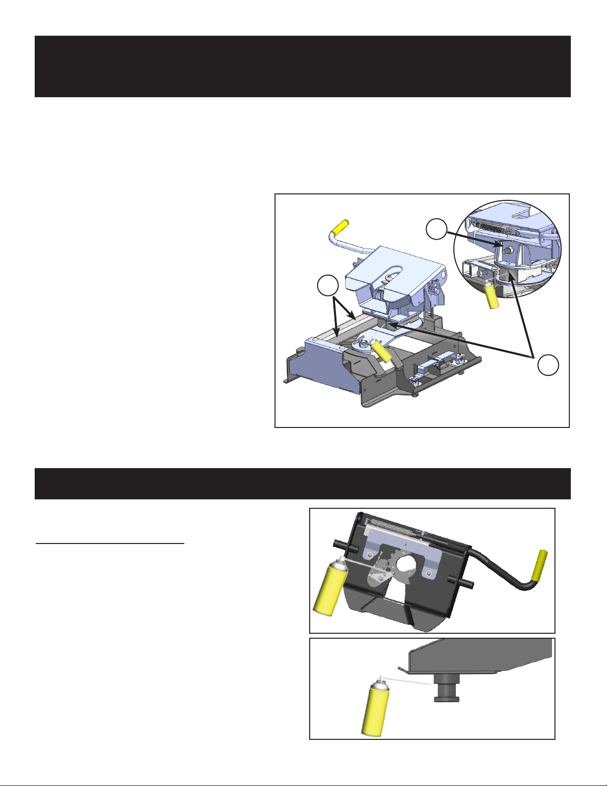
WAY TUBES: Cover the tops and inside face of each Way Tube with WD-40.
TURNTABLE SHAFT: Using a directional straw attached to the spray nozzle, direct oil between the openings in the Low
Friction Polymer Wear Plates at both the front and rear.
PIVOT BOLT AND ROCKER ARM: Inspect and lubricate the Pivot Bolt monthly with axle grease when heavily used, or annually
with light use. To remove the pivot bolt for lubrication:
1. Remove the Fifth Wheel Head Plate from the Rocker
Arm.
2. Remove the Hex Nut and Lock Washer from the
Rocker Arm Pivot Bolt.
3. Place downward force, compressing the Rocker Arm
Spring, enabling the Pivot Bolt to be removed.
4. Lube the Pivot Bolt generously with a quality axle
grease and reinstall. Tighten the Pivot Bolt to the
point where there is resistance when you move the
Rocker Arm side-to-side.
HITCH PINS: A light coating of lubricant such as
WD-40 or 3-in-1 oil on the hitch pin and
clips will help you install and reinstall
them easily.
Passenger side Way Tube removed for illustrative purposes.
1
2
ROCKER ARM
PIVOT BOLT
3
The plate and it’s moving parts should be lubricated
with a light lubricant such as WD-40 or 3-in-1 oil,
before each trip and as needed.
Pull the Release Handle repeatedly so that the lubricant
will spread among the moving parts that may not have
otherwise been covered suciently. Be sure the plate is
free of dirt and old oil buildup.
Be sure the trailer’s king pin is clean and free from rust
and apply lubricant to the king pin.
FIFTH WHEEL PLATE & KING PIN
82.09.21.RH.rev A
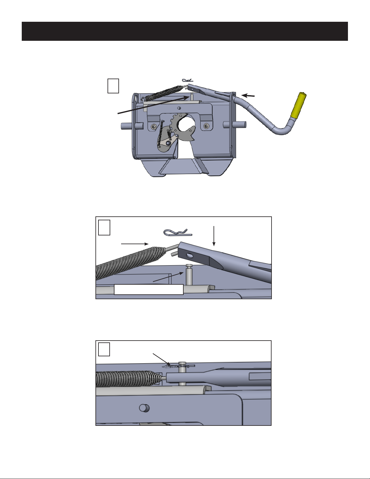
1. Remove the hitch pin clip from the spring post and Insert handle through obround hole.
1OBROUND
HOLE
HITCH PIN CLIP
SPRING POST
2
2. Detach the spring from the spring post and stretch hook inside handle so it reaches beyond the hole in the handle.
3. Bring the handle and sping down over the spring post and replace the hitch pin clip.
3HITCH PIN CLIP
SPRING POST
ATTACH HANDLE TO HEAD PLATE
9
2.09.21.RH.rev A
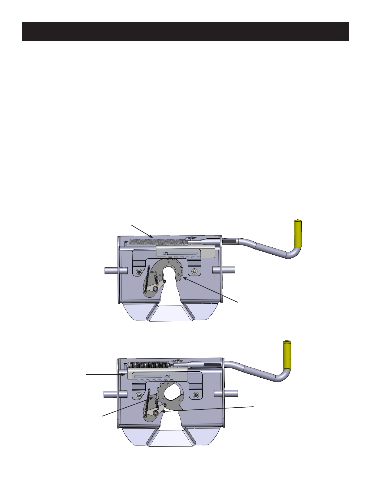
FIFTH WHEEL PLATE OPERATION
A better understanding of the plate’s locking and un-locking operation can be obtained by viewing the working parts
from the underside of the plate. The Fifth Wheel Plate can be removed and turned over to view the workings of the
mechanism. When operating the Fifth Wheel Plate manually, please be aware that the Lock Jaw Assembly has more
movement capability when there is not a king pin present to center the assembly. Refer to the illustrations below for part
identication (#3601 plate pictured below).
1. To open the locking mechanism, lift and pull the Release Handle out until the Lock Catch engages the Lock Jaw
Assembly (see illustrations on the next page)
2. As the trailer king pin moves into the plate, it will contact the Lock Lever, forcing the Lock Catch to disengage the
Lock Jaw Assembly, allowing the Lock Bar Spring to close the Lock Jaw Assembly behind the King Pin. The King Pin
must be fully engaged in the plate slot or the Lock Jaw Assembly will not seat properly, and the Handle Catch would
not then engage the inner side wall of the plate. To be certain that the Lock Jaw Assembly has closed fully, attempt to
pull the Release Handle without rst lifting it.
NOTE: Please note that when lifting the handle to clear the side wall of the plate with the handle catch, it will be
necessary to pull with some force to begin the Lock Jaw rotation. Merely lifting the Release Handle will
not cause the Handle to “pop” open and rotate the Lock Jaw to the open position.
OPEN -UNLOCKED POSITION
LOCK JAW
ASSEMBLY
LOCK BAR SPRING
CLOSED -LOCKED POSITION
LOCK BAR
LOCK CATCH
LOCK LEVER

10 2.09.21.RH.rev A
FIFTH WHEEL PLATE OPERATION
CAUTION: DO NOT ATTEMPT TO TRIP THE LOCK MECHANISM WITH YOUR HAND. USE A PROBE
DEVICE TO SIMULATE THE KING PIN ACTION.
CLOSED
LIFT UPWARD
AND PULL
OUT WITH
FORCE UNTIL
LOCK CATCH
ENGAGES
OPEN
To discourage theft or pranksters, place a padlock through the obround hole above the Release Handle (see
Illustration below).
11
2.09.21.RH.rev A
HITCH INSTALLATION
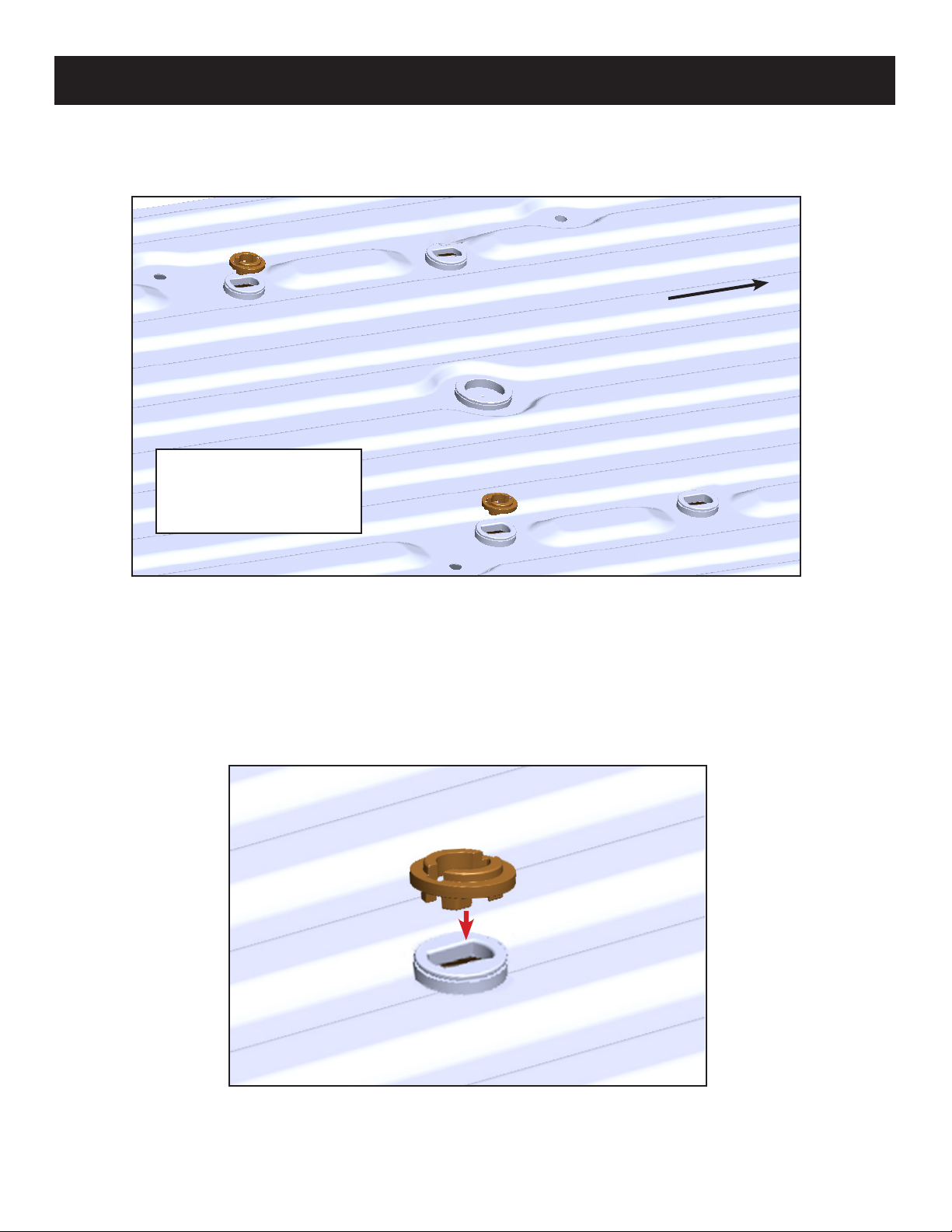
1. Place the (2) Brass Puck Washers into the OE pucks on the side closest to the cab, make sure to orient the Washer
bosses facing downward.
2. Place the SuperGlide onto the pucks. Make sure that the hitch is fully seated on the Brass Puck Washers.
INSERT (2) BRASS
PUCK WASHERS.
ON CAB SIDE
TAILGATE
The OE Series SuperGlide hitch can only be installed on vehicles equipped with the GM Tow Prep Package.
12 2.09.21.RH.rev A
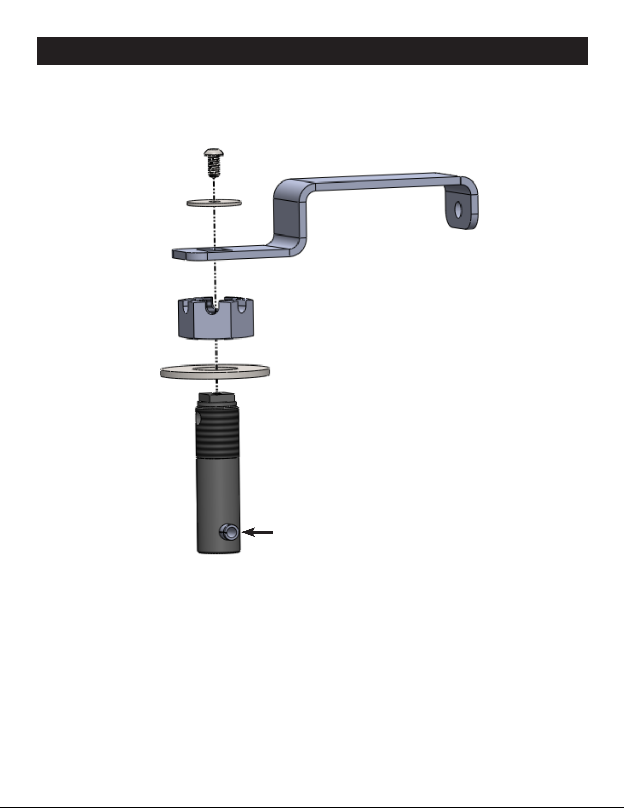
1 - BUTTON HEAD SCREW
2 - WASHER
3 - LOCK HANDLE
4 - CASTLE NUT
5 - BASE WASHER (Driver side only)
6 - POST
2
3
4
5
6
1
BUILD THE POST ASSEMBLY
Build the (4) post assemblies used for clamping the hitch to the bed of the truck. Note that the cross pin is factory set.
1. Place the Base Washer down on the Post (Driver side only).
2. Thread Castle Nut onto the Post.
3. Align the Lock Handle 90 degrees to the direction of the Cross Pin and place on top of the Post, the handle cut-out ts
down over the square top on Post.
4. Add the Washer and Button Head Screw and tighten to 4 ft-lbs*.
* WARNING: This screw should be checked for tightness before each use, and also inspect the handle for proper
seating on the post. This will insure that the post assembly will orient properly and safely secure the hitch
to the truck bed.
CROSS PIN

13
2.09.21.RH.rev A
MOUNTING POST INSTALLATION
Place the hitch post holes directly over the puck, you should be able to adjust hitch base so that each Mounting Post falls
into place as you go. You may have to loosen the Adustment Washers on the passenger side of hitch (see step 5).
NOTE: The rear posts (tailgate side) have larger cross pins than the front posts (cab side). The driver side posts have
the washer under the castle nut, the passenger side does not have these due to Adjustment Washers.
1. Insert each Post Assembly handle into the hitch and orient as seen below (driver side shown below).
2. Rotate handles 90º. Posts may need to be adjusted (see next page).
3. Slide bail pins in through each lock tab and handle. A padlock can also be used here.
4. Repeat steps for the passenger side. Puck Adjustments Washers are present if posts are not easily inserted into the
puck (see step 5).
5. Use a 1/2” Socket Wrench to loosen bolts and move Adjustment Washer plates until posts can be inserted.
6. Re-tighten bolts to 14 foot pounds.
BAIL PIN OR PADLOCK ADJUSTMENT WASHERS
ON PASSENGER SIDE
LOCK TAB
LOCK POSTS BY
TURNING INWARD
3
4
2
1
LOOSEN THESE BOLTS
FOR POST ADJUSTMENT
ON PASSENGER SIDE
5
14 2.09.21.RH.rev A
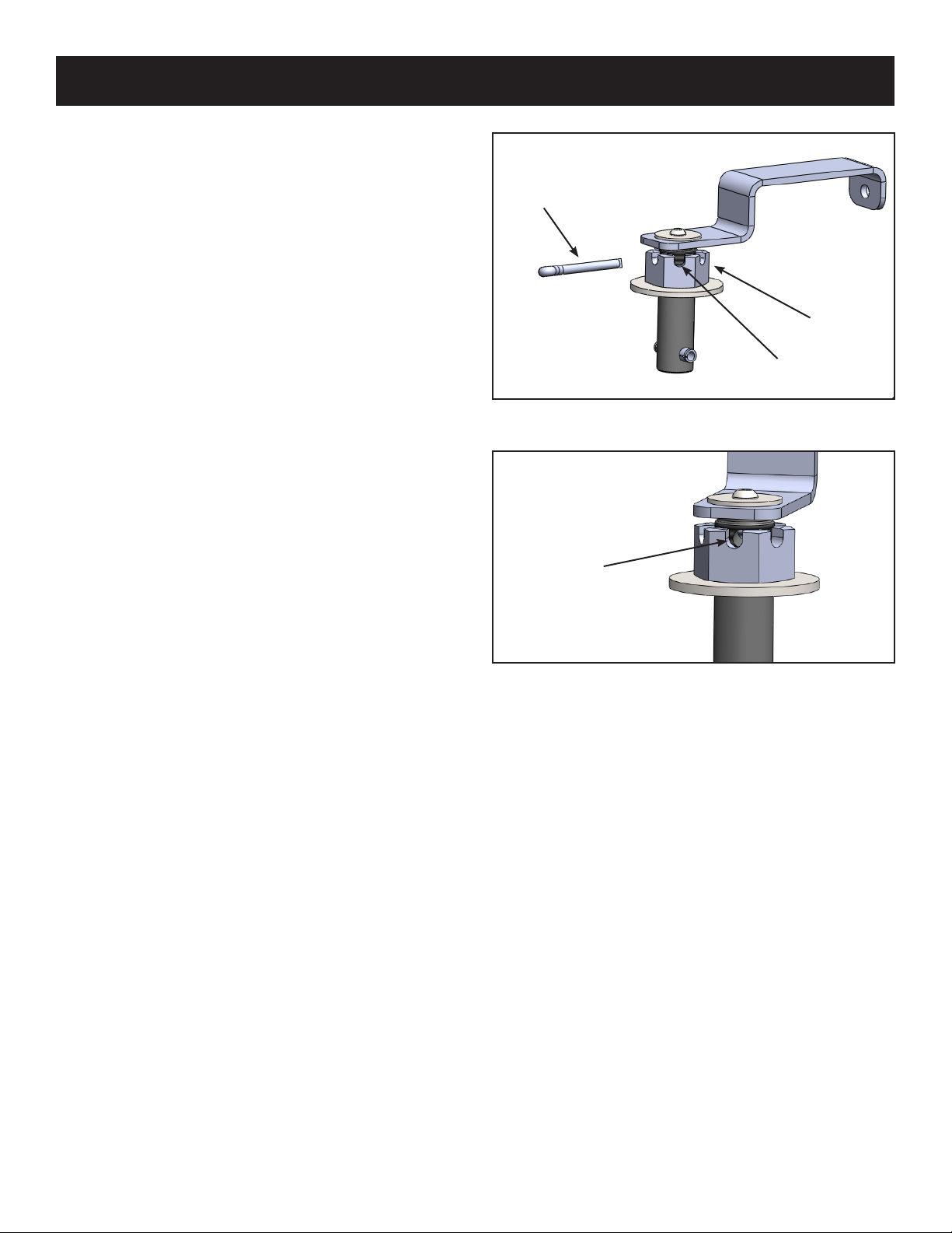
MOUNTING POST ADJUSTMENT
If the OE Series SuperGlide is loose on the mounting
washer or the mounting post will not rotate while seated in
the Puck, the Mounting Post is in need of adjustment. To
adjust the Mounting Post, perform the following:
1. Remove the Cotter Pin from the Mounting Post
Assembly.
2. Rotate the castle nut open until it is near the handle
and then insert the assembly through the opening in
the hitch base into the puck and rotate the handle to
the closed position.
3. Next, lift up on the handle so that the top of the cross
pin touches the bottom of the puck.Thread the nut
down until it bottoms out against the hitch base.
4. Rotate the handle open and closed to test the
tightness “feel”, if the handle rotates with too much
diculty, then back o the castle nut one crenal and
try it again. Likewise, if the handle rotation is too
easy rotate the castle nut one additional crenal. Keep
repeating this action until you have a snug t.
5. Once you have a snug t, remove the post assembly
and insert the cotter pin. Bend the end of the cotter pin
to secure the nut in the chosen position.
6. Re-latch the Mounting Handles as shown on the rst
page of Mounting Post Installation (Page 13).
NOTE: The Castle Nuts may require additional
adjustment (tighter) after hitching for the rst
time and the hitch settles down on the Mounting
Assembly.
COTTER PIN
CASTLE NUT
CRENAL
COTTER
PIN HOLE

15
2.09.21.RH.rev A
HITCHING
WARNING: Never perform any of the following actions while any part of a person is between the vehicle and trailer.
1. Block the trailer wheels in both directions.
2. Align your truck with the center of the trailer. The truck and trailer centerline must be within 10 degrees of each other.
3. Lower your tailgate and back up until there is about 6” of clearance between the SuperGlide hitch and the end of
the Capture Plate (sold separately and installed on your trailer’s king pin plate). Raise or lower the front of the trailer
so the bottom of the Capture Plate is aligned slightly above the beginning of the ramp area of the Fifth Wheel Plate.
This procedure will cause the front edge of the Capture Plate to “ride up” the ramp and atten or tilt the hitch plate
into a parallel position. Add WD-40 to the top of the hitch plate and bottom of the Capture plate and king pin to make
hitching easier.
CAUTION: If this procedure is not followed, the king pin may bind in the plate mechanism and not lock-in properly.
Following the procedure, as outlined in Step 3 will ensure that you will not “high hook” the king pin in the
plate. “High hooking” occurs when backing your hitch into a trailer that is set too high, resulting in the lower
ange of the king pin to wedge itself against the metal edge of the lower horseshoe piece or against the
Lock Jaw Assembly. Damage to the Lock Jaw Assembly may result and not allow smooth operation of the
closing mechanism.
4. The Fifth Wheel Latch must be in the open position (see illustration on page 10). Lift and pull out on the Release
Handle to open the Lock Jaw Assembly.
CAUTION: Damage may result should you attempt to hook up with the Lock Jaw Assembly in the closed position.
5. Back up the truck in one uid motion, so the king pin enters the center of the Fifth Wheel Plate opening.
6. Set your parking brake while the king pin is pressed against the hitch and you feel it stop the rearward roll of your
truck.
7. Make sure the Lock Jaw Assembly is completely wrapped around the king pin.
8. Be sure that the Release Handle has fully returned to the closed position and proceed to Safety Checks (page 16).
CAPTURE PLATE
RAMP
CAPTURE PLATE
(UNDERSIDE VIEW)

16 2.09.21.RH.rev A
SAFETY CHECKS
UNHITCHING
1. Shine a light on the Fifth Wheel Plate Lock Jaw Assembly making sure it has closed around the king pin.
2. Pull the Release Handle towards you without lifting it up. If the Lock Jaw Assembly is completely closed the Handle
Catch will prevent you from being able to pull the Release Handle open.
3. Raise the trailer jack base plates just above the ground, lock your trailer brakes, then pull the tow vehicle slowly
forward putting a strain on the trailer.
4. When you are assured that the trailer is safely hooked up, raise your trailer jacks into their full retracted position.
FAILURE TO PERFORM THESE SAFETY CHECKS MAY RESULT IN DAMAGES TO TRUCK AND TRAILER.
WARNING: Never perform any of the following actions while any part of a person is between the vehicle and the trailer.
1. Once you have the trailer located and are ready to unhitch, block the trailer wheels so it will not roll back or forward.
Back into the blocked trailer slightly and set the parking brake while you are still in gear. This action will relieve
pressure on the lock mechanism before attempting to release the latch mechanism.
2. Lower the trailer jacks to the point of just touching the ground but do not raise the trailer at this point.
3. Open the Lock Jaw Assembly by rst lifting, then pulling the Release Handle towards you (see pages 9 & 10).
4. Lower the trailer jacks until the bottom of the king pin box is almost free of the top of the Fifth Wheel Plate. Make
certain that the bottom of the king pin is not so high that binding on the hitch Lock Catch would result.
5. After lowering the truck’s tailgate, disconnect the trailer electrical cord and break-away switch cable, then pull forward.
6. As the king pin slides from the Fifth Wheel Plate, notice that the locking mechanism remains open once the king pin is
removed.
CAUTION: If it should be necessary to reposition your trailer, you must follow the hitching procedures to ensure the
hitch is latched before moving the trailer.
CAUTION: You may wish to keep the plate closed until you are ready to re-hitch to avoid injury or accidents to
children or adults who attempt to operate the plate mechanism. DO NOT ATTEMPT TO TRIP THE LOCK
MECHANISM WITH YOUR HAND, USE A PROBE TO SIMULATE THE KING PIN.
17
2.09.21.RH.rev A
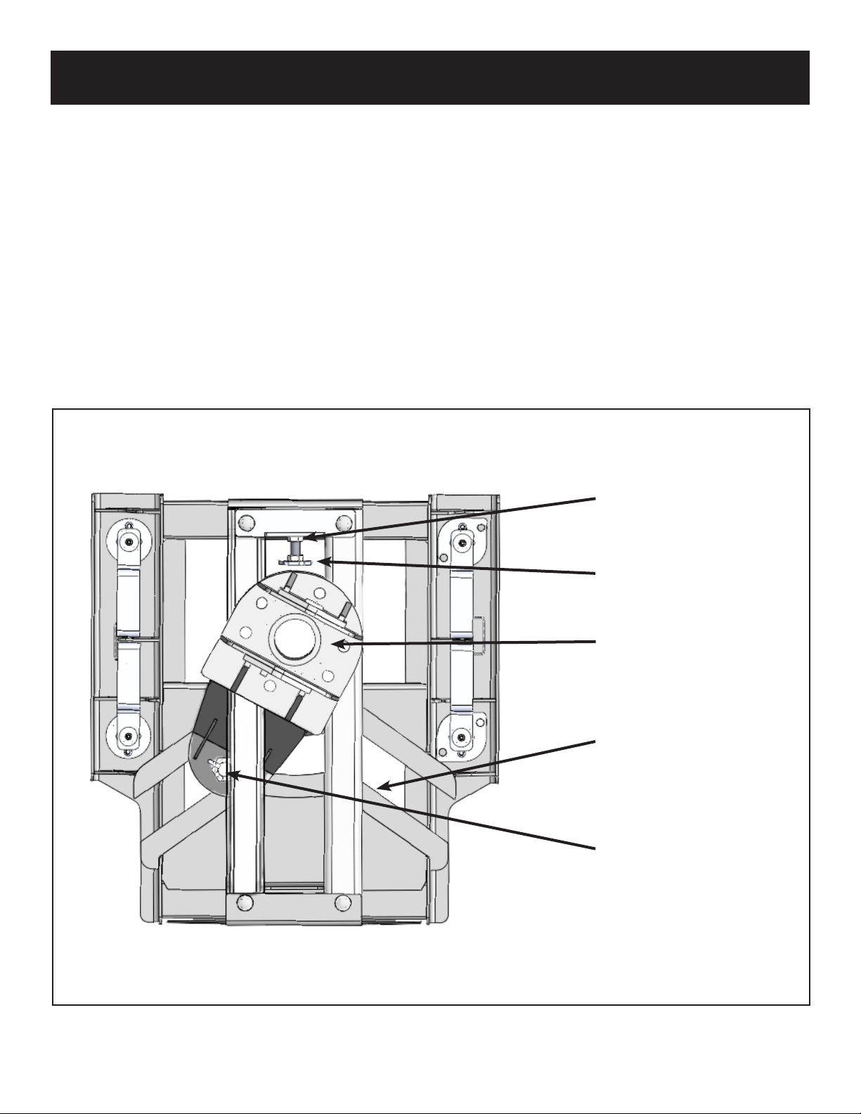
ADJUSTING THE TURNTABLE CAM ARM ASSEMBLY
This adjustment will need to be made periodically. If you are experiencing a bump or “clunk” when starting or stopping,
or if the hitch is sliding up and down the way tubes when you are not hooked up to the trailer you can perform this
adjustment to reduce the noise and keep the hitch in the forward towing position when not trailering.
1. The Turntable Cam Arm Roller needs to be kept snug against the rear edge of the of the Cam Slot (see below).
2. To adjust, loosen the Jam Nut located on the Threaded Stop Assembly, under the Fifth Wheel Plate (on the side facing
the front of your truck).
3. Adjusting the Threaded Stop Assembly’s hex-shaped plate, will remove excessive play from between the Low Friction
Polymer Wear Plates and the Turntable Cam Arm Roller.
4. Turn the hex-shaped plate of the Threaded Stop Assembly by hand, adjusting incrementally, until resistance is felt
when pulling the Turntable Cam Arm Assembly aligned straight from front to back. While holding the hex-shaped
plate in place, tighten the Jam Nut with a wrench. The Cam Arm Assembly should be tight enough on Threaded Stop
Assembly that you can barely move it by hand.
ROLLER
REAR EDGE OF
CAM SLOT
TURNTABLE CAM ARM
ASSEMBLY
THREADED STOP
ASSEMBLY
THREADED STOP
ASSEMBLY JAM NUT

18 2.09.21.RH.rev A
CHALLENGE VS. SOLUTION
CHALLENGE SOLUTION
Cannot open the Release Handle. You may have too much rearward pressure against the lock
mechanism. Back your truck slightly to relieve pressure and set
your parking brake before shifting to park. Continue with the un-
hitching procedures.
The latch handle mechanism seems too sti to
operate.
Spray the locking mechanism with WD-40. Work the handle until
it slides freely. If the problem persists, you may need to degrease
and re-lube all working parts.
I need to have a professional evaluate OE
Series SuperGlide.
Contact PullRite’s Customer Service Dept. at (800) 443-2307.
Your needs will be assessed and resolved by PullRite or you will
be directed to an authorized PullRite Service Center.
Hitch seems loose on the Mounting Posts. You may need to adjust them. Refer to the “Mounting Post
Adjustment” section (page 14).
The Mounting Posts will not rotate into the
“locked” position.
You may need to adjust them. Refer to the “Mounting Post
Adjustment” section (page 14).
NOTE:Most challenging issues can be solved with the use of lubrication such as WD-40 on moving parts (or a
graphite based spray like Slip Plate when the application is metal-to-metal).

19
2.09.21.RH.rev A
FREQUENTLY ASKED QUESTIONS
1. Can I pull other Fifth wheel trailers with my SuperGlide hitch?
Your SuperGlide hitch can only pull trailers equipped with the SuperGlide Capture Plate. If you hook up to a trailer that
does not have a Capture Plate installed, there is no control to keep the hitch in the forward towing position and the weight
of the trailer will cause the head to turn and slam or “free fall” to the rear of the hitch’s angled cam slot, which may cause
damage to the hitch, truck, and the king pin. We do not recommend locking the hitch in any way to keep it in the forward
position.
2. Will a standard hitch be able to tow my trailer with the Capture Plate installed?
The Capture Plate will need to be removed from the pin box before a standard fth wheel hitch can tow your trailer. If the
plate is not removed, the king pin will not rotate in the hitch and damage will result to the Capture Plate and conventional
hitch. Most of Pullrite capture plates are easily removed, If however, you cannot remove the Capture plate, part # 3336
is a conversion adapter that will allow a standard fth wheel hitch to tow your trailer with the Capture Plate installed. The
adapter is used in conjunction with your Fifth Wheel Plate, or “head” of the SuperGlide.
3. Is there a cover available for my SuperGlide hitch?
Please contact Customer Service at (800) 443-2307 for availability..
4. How much does my SuperGlide weigh?
The #4500 weighs 209 lbs. Lifting weight with the Head Plate removed is 169 lbs.
5. Can I leave the hitch attached to my trailer and use the trailer jacks to lift the hitch out of the truck?
Yes, you can use the trailer jacks to lift the hitch out of the truck. The hitch should not be left hanging from the king pin.
Once you have the hitch lifted out of the truck you should have a stand available to lower the hitch onto for storage.
6. Can I hook up or unhook at a 90 degree angle?
Hooking up can only be accomplished when the truck and trailer are aligned within 10 degrees of each other. See
“Hitching” (page 15). for more information on hooking up. Unhooking by pulling the release handle can only be
accomplished when the truck and trailer are aligned within 10 degrees of each other.
In emergency situations you can pull the clevis pins and clips that attach the Fifth Wheel Plate or “head” assembly to the
Rocker Arm, lower your landing gear and raise the trailer up until the Fifth Wheel Plate is free from the Rocker Arm. Pull
forward from under the parked trailer. At that point you can pull the Release Handle, remove the head from the king pin
and reattach it to your hitch with the clevis pins and clips.
7. Can I use a Teon disc or lube plate on the king pin plate?
The king pin box and SuperGlide plate or “head” move together and since there is no friction, there is no need for any
grease or a lube plate. Use of a Teon disc or lube plate would cause the king pin to be too short and problems hooking
up will occur.

20 2.09.21.RH.rev A
2
5
7
3
6
8
9
4
11
12
15
14
1
18
19
24
21 22 23
25
26
27
EXPLODED VIEW
10
CAB SIDE
REAR SIDE
29
28
13
30
32
33
34
35
36
37
38
39
20
31
16
17
This manual suits for next models
1
Table of contents
Other PullRite Automobile Accessories manuals


Popular Automobile Accessories manuals by other brands

CipherLab
CipherLab 9500CE Series Quick installation

Thule
Thule Crossroad Railing Foot 450 installation guide

Metra Electronics
Metra Electronics MPS-GEN01 installation instructions

Cruz
Cruz Evo Rack E30-170 Assembly instructions

Innogy
Innogy eBox touch Instructions for use

Britpart
Britpart VUB000730 Fitting instructions


