LUXEOS RANGE
P U L S A R
1 Pembroke Avenue, Waterbeach, Cambridge, CB25 9QP
2 of 12
INSTALLATION
7650-INST-ALL
P U L S A R
1 Pembroke Avenue, Waterbeach, Cambridge, CB25 9QP
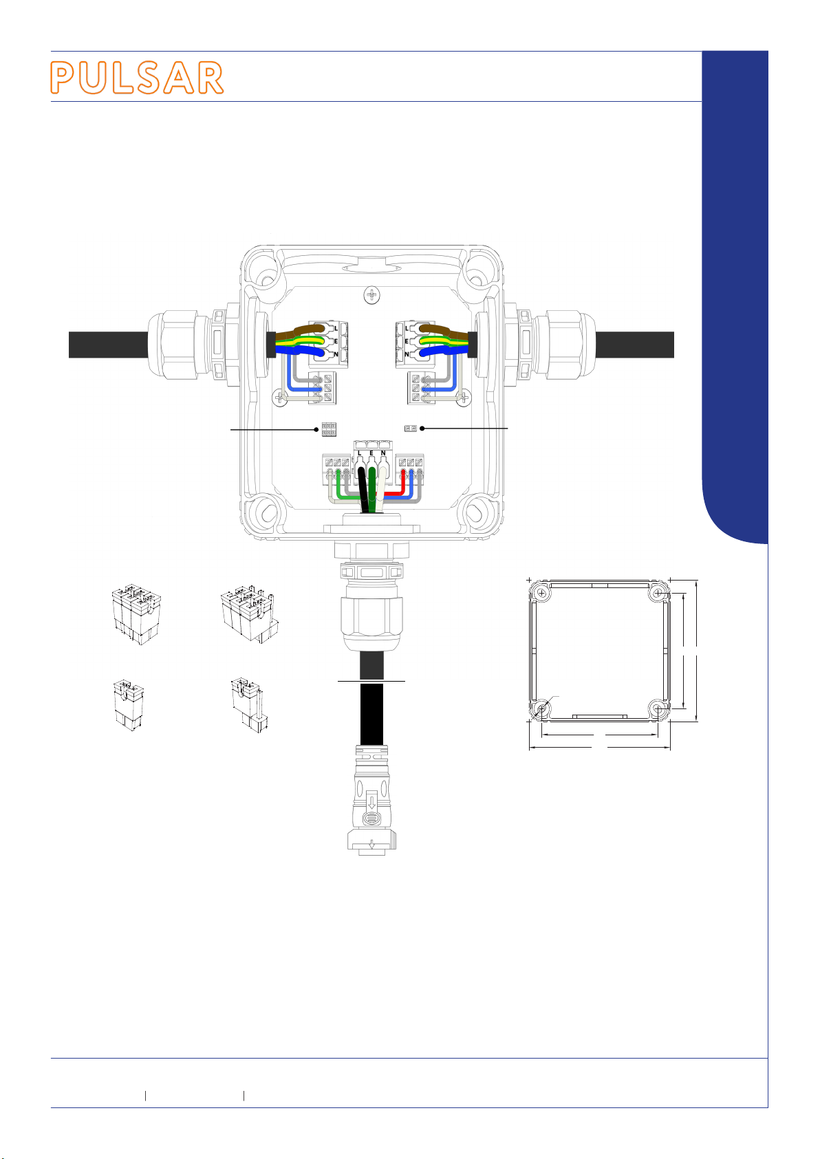
Jumper J1 in pass- through position
(jumpers connected)
In this position DMX will be passed from input to
output with or without the luminaire in place.
It is not recommended to use the jumpers
in this position if the luminaire is connected
because a single spur DMX line is created
DMX Line termination J2 in enabled position
(jumper connected)
This should be enabled if the luminaire is the
last in the DMX chain
SCREEN
DATA -
DATA +
SCREEN
DATA -
DATA +
SUPPLY IN / THRU 240VAC 20A MAX
J1 DMX PASS THRU J2 DMX TERM
LIVE
NEUTRAL
EARTH
LUMINAIRE
DMX IN/THRU
DMX + WHITE
DMX - GREEN
SCREEN
DMX + RED
DMX - BLUE
SCREEN
-SCR +-SCR
LUMINAIRE
DMX IN/THRU
Power
The power cable should be no greater than 4mm2 and can be either stranded or solid cores.
The maximum current of each cable run should be no greater than 20A continuous.
Before tting the power cable, each cable end should be stripped to between 9 and 11mm before inserting into the connectors.
Ensure connections are made in accordance to the markings on the PCB, failure to do so may result in damage to the luminaire.
DMX
Before tting the DMX cable, each cable end should be stripped to between 8.5 and 9.5mm before inserting into the connector.
Ensure connections are made in accordance to the markings on the PCB, failure to do so may result in incorrect operation or damage to the luminaire.
IMPORTANT: If the insulation rating of the DMX cable is less than the supply voltage then additional protective sleeving should be tted.
DMX Passthrough
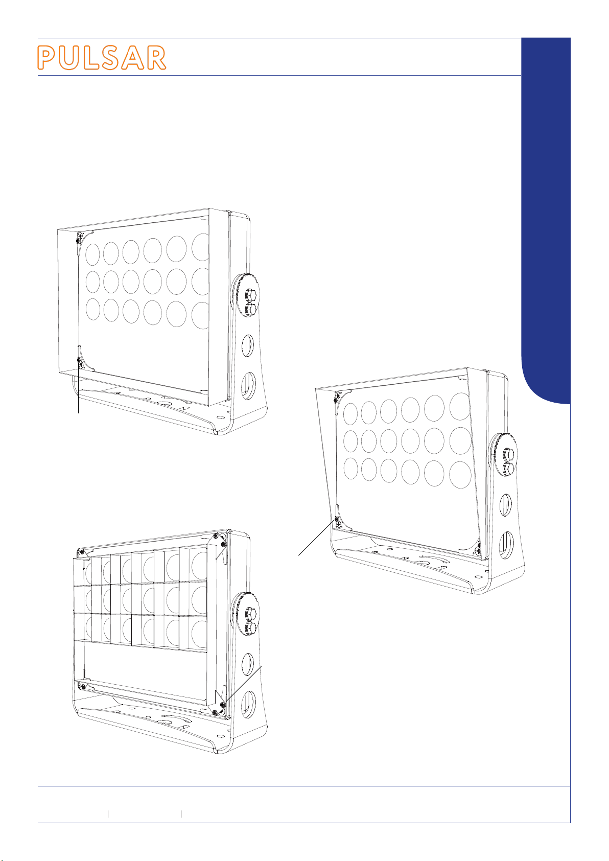
When commissioning the installation before the luminaires are connected, or if a luminaire has been removed, the DMX signal can be passed through by repositioning the jumpers (J1)
as indicated within the install box.
Combined Power & DMX input cable Combined Power & DMX through cable
Combined Power & DMX cable with
LuxEOS line mount QuickLINK+ connector
J1 in pass through position J1 in luminaire through position
J2 DMX termination enabled J2 DMX termination disabled
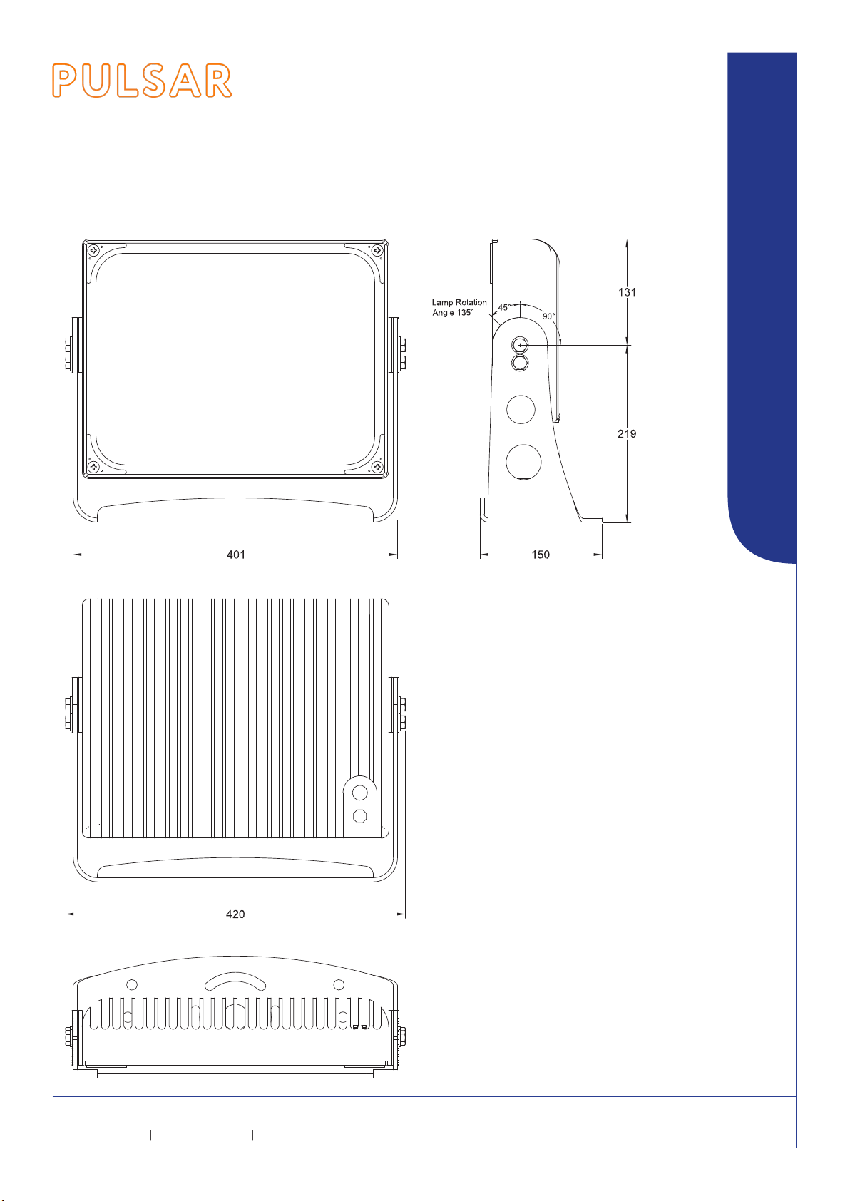
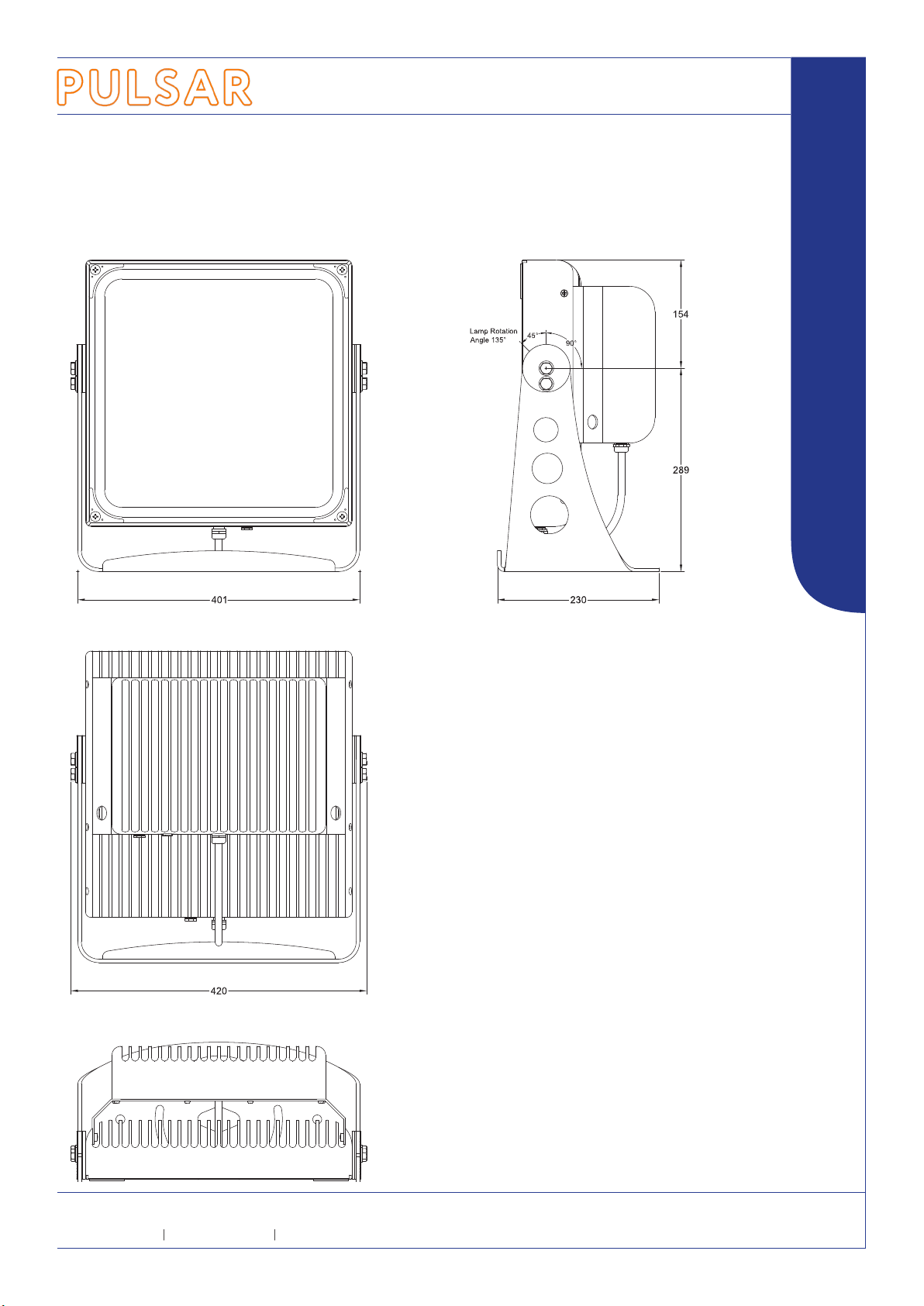
+
110
90
Ø5
Connection box
mounting details
(dimensions in mm)
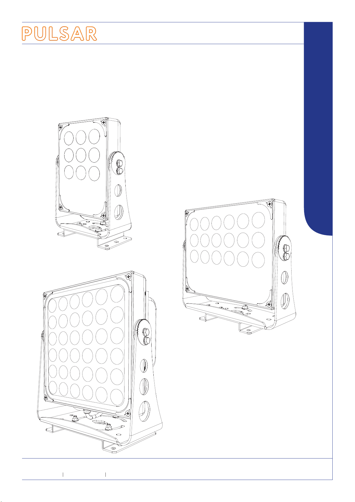
LUXEOS Flood 9 18 36 Beam 20 40 80
LED LUMINAIRES FOR ARCHITECTURAL LIGHTING
LuxCONNECT IP66 Hardwired connection enclosure with combined Power & DMX input & QuickLINK+ luminaire connection
-
WIRING DETAILS
11090
Depth (including Lid)
65