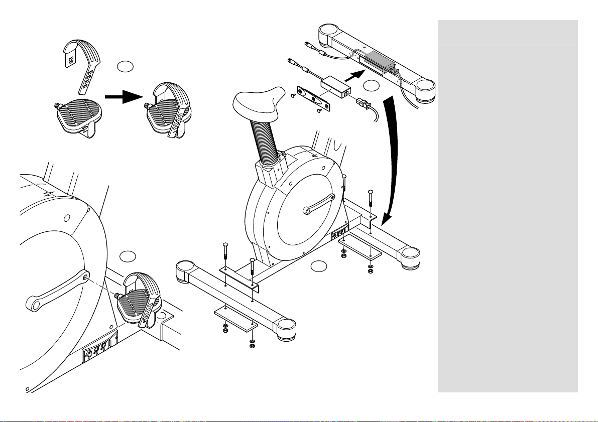
Assembly of 240F Cycle1
Assemble the foot straps onto the
pedals.
The External Power Box has to be
located inside the Front Feet Strut.
Firstly attach the Power Box onto
the PSU Cover Moulding, using the
velcro strip. Carefully slide the
Power Box cable from inside the
feet strut through the grommet in
the base. Slide the Mains power
cable in through the other
grommet and connect to the
Power Box. Carefully push the PSU
Cover Moulding into place and
secure with the Pine Tree Clips.
Place the main body onto the feet
struts (this is a two person
procedure) then place the feet
strut plates underneath the feet
struts and secure with feet strut
bolts, washers and nuts.
Attach the pedals onto the crank
arms (the pedals are handed and
therefore should be attached as
indicated by the letter L or R on
the underside of the pedal).
NOTE: Ensure the pedals are
securely fastened before using the
cycle.
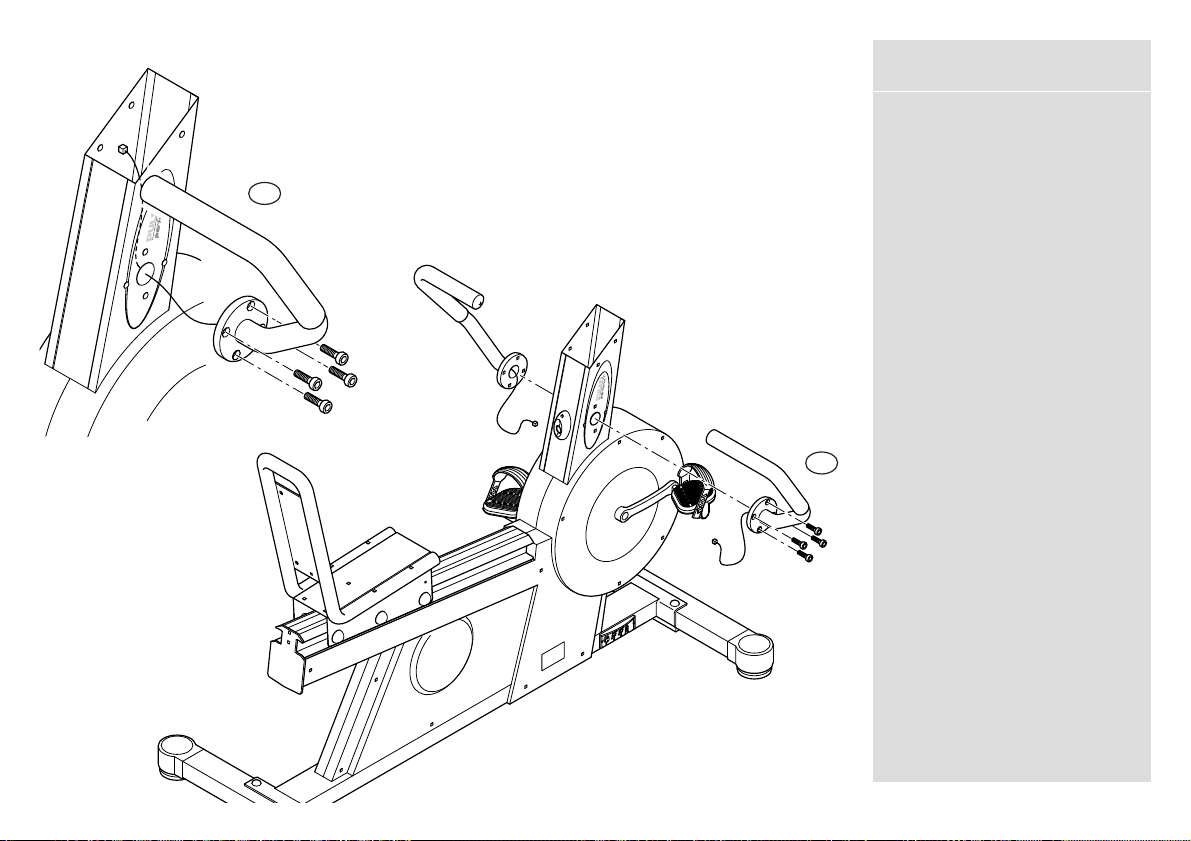
Tools Required -
1 x 15/13mm Combination
Spanner.
(1)
(2)
(3)
(4)
5
1
3
4
2
Viewed from front