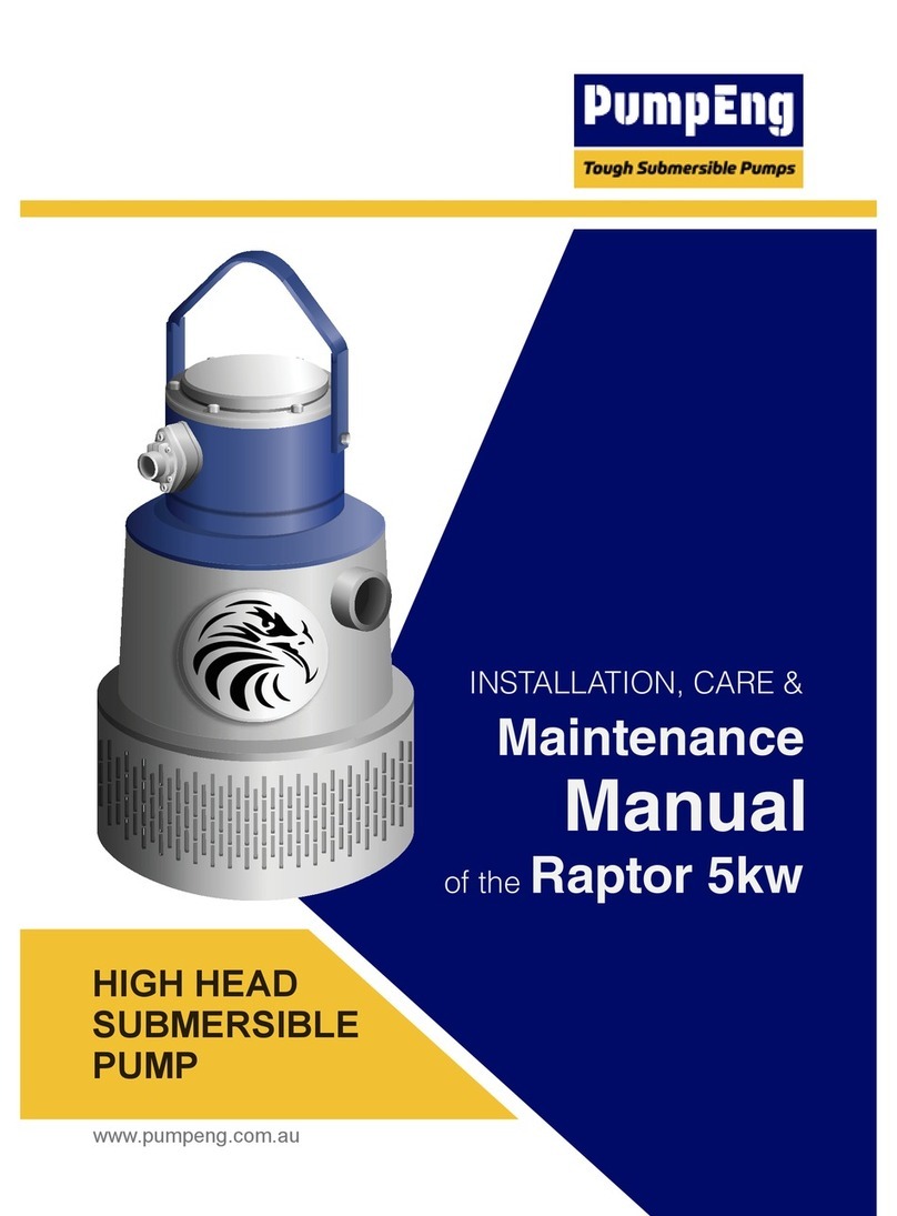
pumpeng CorroTuff CT Series Installation and operating instructions

www.pumpeng.com.au
DRAINAGE
SUBMERSIBLE
PUMP
CT
CTS
Manual
OPERATION &
of the
SERIES
Service
&
CorroTuff

1 of 36
www.pumpeng.com.au
6
10
13
14
22
28
35
6
7
8
8
9
10
10
12
12
13
13
13
13
15
16
19
19
20
22
23
25
26
27
29
29
30
32
02. Introduction
03. Product Description
04. Prior to Use
05. Installation
06. Operation
07. Maintenance and Inspection
08. Trouble Shooting
1.) Safety terminology and symbols
2.) Product warranty
3.) Safety
4.) User safety
5.) Environment safety
1.) Pump design
2.) Intended use
3.) The data plate
4.) Pump part names
1.) Inspect the product
2.) Inspect the specification
3.) Product specification
4.) Method of starting
1.) Preparation for installation
2.) Install the pump
3.) Make the electrical connections
4.) Grounding
5.) Connecting the cables
1.) Before operation
2.) Trial operation
3.) Operation
4.) Motor protection system
5.) Water level during operation
1.) Inspection
2.) Storage
3.) Maintenance
4.) Disassembly and reassembly procedure
Manual Contents
01. Company Profile
2

Introducing JetGuard®
Why is JetGuard® Better?
2 of 36
www.pumpeng.com.au
Performance: increase mine performance, productivity and profit by
reducing breakdowns and delays.
Safety: reduce workplace hazards by reducing the number of
breakdown maintenance events.
Cost: reduce equipment life cycle cost by increasing total pump life.
•
•
•
Introducing PumpEng
Company Prole
PumpEng is an Australian company founded in 2001 that specialises in submersible
pumps for use in mining, construction and industrial dewatering. Founder Paul Meneghel
has experience in submersible pumps and mining stretching back to the 1980s.
PumpEng uses innovative design to manufacture pumps that perform well in the toughest of
circumstances. PumpEng has been successful in the Australian market with its innovative
line of Raptor® pumps. Now PumpEng have launched a new pump - JetGuard®- that uses
patented design innovations to better handle underground mining conditions including
the presence of Shotcrete fibre and other tramp material.
What Does a Broken Pump Really Cost a Mining Operation?
Many dewatering pumps were designed before Shotcrete was
widely used in underground mining. Shotcrete fibres are now
a major cause of underground pump failure and production
delay. In a multi million dollar operation, even small delays can be
expensive.
Benefits of JetGuard® for Mining Operations
PROTECTED - Less Fibre Gets In
A hydraulic curtain repels surface fibre, and the suction strainer intake is on the bottom of
the pump, not the side. So less Shotcrete fibre gets inside. If any fibres do get in, a cutter
plate chops up fibres into tiny pieces.
TOUGHENED - Less Damage Gets Done
Internal components in the wet end are tough metal, not elastomer. Fibre and tramp can
more quickly destroy elastomer components, while toughened steel components power on.
The mechanical seal is in a non pressurised zone, away from the high pressure intake area
and removed from the fluid/Shotcrete path.
PRODUCTIVE - Less Downtime More Production
JetGuard® has been designed for tough environments, to keep on pumping when traditional
dewatering pumps might fail.

3 of 36
www.pumpeng.com.au
Heavy duty underground dewatering pump. Shotcrete handling capability, all
metal wet end, electro submersible pump with high chrome impeller.
10Kw (20Kw and 37Kw planned)
Underground dewatering submersible. Compatible with Xylem/Flygt Bibo range.
5Kw to 20Kw
Heavy duty submersible sludge/slurry pump with high chrome impeller &
agitator. Flows available up to 83 l/s and heads up to 35 m.
1.5Kw to 22Kw
A 415v range of pumps with smart technology. Stainless Steel with a HRC
impeller.
1.5Kw to 22Kw
A pump designed to handle solids without damaging the product.
4Kw to 18.5Kw
Small 240v grinder pump for dirty water applications.
0.75Kw to 1.1Kw
Capability Statement
Submersible Pump Range
JetGuard®
Raptor®
ScatPump®
CorroTuff®
Vortex
MetalVest™ submersible pumps use a full metal build, so there is no urethane
or rubber lined parts for a longer life available in 1000v & 415v. The cylindrical
MetalVest™ HHS Slimline is designed for those places where physical size is an
issue. It fits inside caissons for offshore requirements.
4Kw to 18.5Kw
The Heavy Duty MetalVest HH for those tough conditions 37kw.
MetalVest
Grinder
PumpEng manufacture and sell tough submersible pumps suitable for underground
mining and other heavy duty applications. We innovate to increase operational reliability
and productivity.
Disclaimer: PumpEng Pty Ltd is not an authorized distributor of parts or services for
the products of Xylem. PumpEng Pty Ltd products are not associated with, endorsed
by or sponsored by Xylem. Any use of Xylem names, trademarks, model no, item no or part no is
for reference purpose only. Flygt is a registered trademark of Xylem.

4 of 36
www.pumpeng.com.au
Vision & History
PumpEng stock an extensive range of spare parts. The entire range of PumpEng
submersible pumps is available for hire Australia wide on short and long term contracts.
A range of service programs are available, and can be tailored to your requirements.
To ensure you never pay too much for our services, we offer a price guarantee on our product
range. This effectively caps your maximum repair price. Simply send us your old pump if
it goes over our limit and we will supply you with a PumpEng manufactured replacement.
•
•
•
•
•
•
Our vision is to be the specialist in tough submersible dewatering pumps based on:
Innovative thinking: To offer solutions to customer needs.
Product availability: Products available on time every time.
Technically sound product & system advice: Supplying the correct product
every time.
After sales support: Providing support to our customers after the initial sale.
Our goals are:
Develop & manufacture our own product range to give us product security and introduce
these products into the market place with respect to our core values.
Develop brand name & product recognition of our products to ensure future growth,
security & profit.
PumpEng is an Australian company founded in 2001 that specialises in submersible pumps
for use in mining, construction and industrial dewatering. Founder Paul Meneghel has
experience in submersible pumps and mining stretching back to the 1980s. We are now a
well established specialist submersible pump supplier to a wide range of customers across
Australia, and are addressing global opportunities.
We have developed a team of experienced staff enabling us to satisfy our customers needs which
vary from the design, manufacture and supply of our pumps to the expedient repair/ rebuild & full
aftermarket support of our product range. The skills of our staff are further enhanced through the
alignment of PumpEng with major foundries and engineering facilities located within Australia as well
as abroad.
PumpEng’s philosophy is to provide exceptional product and follow on with first-rate sales service and
support. We aim to provide a Total Dewatering Solution.
Parts, Hire & Service - A Full Service Provider

Plant & Equipment
5 of 36
www.pumpeng.com.au
Warranty
PumpEng will repair faults in the products we manufacture within the following constraints:
Our Perth, Kalgoorlie & Mount Isa branches comprise of stock holding as well as
assembly, testing, fabrication and repair facilities. We have all the equipment needed to
fully support our pump range including a custom built test facility which is able to test to
AS 2417 Standards.
Our workshop is one of the few pump facilities in Western Australia incorporating a 1000v
test bay and is equipped with a 200kva, 1000v transformer. Our manufacturing facilities in
Western Australia and internationally have strict adherence to quality procedures throughout
all stages of manufacture.
The fault has been caused by defects in materials or workmanship.
The fault has occurred when the product is used in circumstances to which the product
was intended to be operated in and in accordance with installation and operating
recommendations.
All repairs and regular maintenance is performed by an authorized PumpEng repair
dealership.
All components used in servicing and repairs must be genuine PumpEng
components.
The fault is not caused by inadequate maintenance.
The fault occurs and is reported to PumpEng or an authorized PumpEng
dealership within twelve (12) months of purchase.
The product is returned to PumpEng or an authorized dealer at nil expense to the
receiver.
PumpEng accepts nil liability for consequential damage or losses.
PumpEng reserves the right to alter information and specifications without notice.
•
•
•
•
•
•
•
•
•

Introduction
6 of 36
www.pumpeng.com.au
Purpose of This Manual
The purpose of this manual is to provide necessary information for:
• Installation
• Operation
• Maintenance
CAUTION:
Read this manual carefully before installing and using the product. Improper use of the
product can cause personal injury and damage to properly, and may void the warranty.
NOTICE:
Save this manual for future reference, and keep it readily available at the location of
the unit.
Safety Terminology and Symbols
About Safety Messages
Is is extremely important that you read, understand, and follow the safety messages
and regulations carefully before handling the product. They are published to help
prevent these hazards:
• Personal accidents and health problems
• Damage to the product
• Product Malfunction
Hazard Levels
A hazardous situation which, if not avoided, will result in death or
serious injury.
•
•
•
A potential situation which, if not avoided, could result in undesirable
conditions.
A practice not related to personal injury.
A hazardous situation which, if not avoided, could result in minor or
moderate injury.
A hazardous situation which, if not avoided, could result in death or
serious injury.
•
•
HAZARD LEVEL
DANGER:
WARNING:
CAUTION:
NOTICE:
INDICATION

Introduction
7 of 36
www.pumpeng.com.au
Hazard Categories
Hazard categories can either fall under hazard levels of let specific symbols replace
the ordinary hazard level symbols. Electrical hazards are indicated by the following
specific symbol:
•
Product Warranty
Coverage
PumpEng undertakes to remedy the following faults in products sold by PumpEng
under the following conditions:
• The faults are due to defects in design, materials or workmanship.
• The faults are reported to an PumpEng representative within the warranty period.
• The product is used only under the conditions described in this manual.
• The monitoring equipment incorporated in the product is correctly connected and in use.
• All service and repair work is done by personnel authorized by PumpEng.
• Genuine PumpEng parts are used.
Limitations
The warranty does not cover faults caused by the following:
PumpEng assumes no liability for the following:
• Deficient maintenance.
• Improper installation.
• Modifications or changes to the product and installation carried out without consulting PumpEng.
• Incorrectly executed repair work.
• Normal wear and tear.
Warranty Claim
PumpEng products are high-quality products with expected reliable operation and long
life. However, should the need arise for a warranty claim; please contact your PumpEng
representative.
• Bodily injuries.
• Material damages.
• Economic losses.
ELECTRICAL HAZARD:
These are examples of other categories that can occur. They fall under the ordinary
hazard levels and may use complementing symbols:
• Crush hazard
• Cutting hazard
• Arc flash hazard

PumpEng guarantees that spare parts will be availble for 10 years after the manufacture
of this product has been discontinued.
8 of 36
www.pumpeng.com.au
Safety
CAUTION:
You must observe the instructions contained in this manual. Failure to do so could result
in physical injury, damage, or delays.
WARNING:
•
•
•
•
•
The operator must be aware of safety precautions to prevent physical injury.
Any pressure-containing device can explode, rupture, or discharge its contents
if it is over-pressurized. Take all necessary measures to avoid over-pressurization.
Operating, installing or maintaining the unit in any way that is not covered in this
manual could cause death, serious personal injury, or damage to the equipment by
PumpEng. If there is a question regarding the intended use of the equipment, please
contact an PumpEng representative before proceeding.
This manual clearly identifies accepted methods for disassembling units. This meth-
ods must be adhered to. Trapped liquid can rapidly expand and result in a violent ex-
plosion and injury. Never apply heat to impellers, propellers, or their retaining devices
to aid in their removal.
Do not change the service application without the approval of an authorized PumpEng
representative.
User Safety
General safety rules
These safety rules apply:
• Always keep the work area clean.
• Pay attention to the risks presented by gas and vapors in the work area.
• Avoid all electrical dangers. Pay attention to the risks of electric shock or arc flash hazards.
• Always bear in mind the risk of drowning, electrical accidents, and burn injuries.
NOTICE:
Never operate a unit unless safety devices are installed. Also see specific information
about safety devices in other chapters of this manual.
NOTICE:
When purchasing pump parts, please provide product code showed at the nameplate.
Introduction
Spare Parts

Electrical connections must be made by certified electricians in compliance with
all international, national, state and local regulations. For more information about
requirements, see sections dealing specifically with electrical connections.
The product is designed for use in liquids that can be hazardous to your health.
Observe these rules when you work with the product:
•
•
Make sure that all personnel who work with biological hazardous liquids are
vaccinated against diseases to which they may be exposed.
Observe strict personal cleanliness.
Wash the skin and eyes
Follow these procedures for chemicals or hazardous fluids that have come into contact
with your eyes or your skin:
Hold your eyelids apart forcibly with your fingers.
Rinse the eyes with eyewash or running water for at least 15 minutes.
Seek medical attention.
1.
2.
3.
Remove contaminated clothing.
Wash the skin with soap and water for at least 1 minute.
Seek medical attention, if necessary.
1.
2.
3.
CONDITION
Chemicals or
hazardous fluids
in eyes
Chemicals or
hazardous fluids
on skin
ACTION
Environmental Safety
The work area
Always keep the station clean and/or discover emissions.
Waste and emissions regulations
Observe these safety regulations regarding waste and emissions:
•
•
•
•
Dispose appropriately of all waste.
Handle and dispose of the processed liquid in compliance with the applicable
environmental regulations.
Clean up all spills in accordance with safety and environmental procedures.
Report all environmental emissions to the appropriate authorities.
Electrical installation
For electrical installation recycling requirements, consult your local electric utility.
9 of 36
www.pumpeng.com.au
Electrical connections
Introduction
Hazardous Liquids

Work drainage and sand carrying/0 to 40°C
Open or Close
Double mechanical seal
FLUID
PUMP
MOTOR
TYPE/TEMPERATURE
IMPELLER
SHAFT SEAL
BEARING
TYPE, POLES
INSULATION
LUBRICANT
MOTOR PROTECTOR
(BUILT-IN)
DISCHARGE CONNECTION
Sealed ball bearing
Circle thermal protector
Dry type submersible induction motor 2 poles, 4 poles
Miniature protector (Non-standard parts)
Class F
Turbine oil VG32
House coupling, Hard pipe
Intended Use
The product is intended for moving waste water, raw and clean water. Always follow the
limits given in Application limits (page 9). If there is a question regarding the intended
use of the equipment, please contact a PumpEng representative before proceeding.
WARNING:
Only Ex-approved pumps may be used in an explosive or flammable environment.
NOTICE:
Do not use the pump in highly corrosive liquids.
10 of 36
www.pumpeng.com.au
Product Description
Recycling Guidelines
Pump Design
Always recycle according to the guidelines listed below:
•
•
Follow local laws and regulations regarding recycling if the unit or parts are accepted
by an authorized recycling company.
If the first guidelines is not applicable, then return the unit or parts to the nearest
PumpEng representative.

11 of 36
www.pumpeng.com.au
LEGEND
NO.
10
9
Max. capacity
Mas. immersion depth
Max. liquid temperature
Max. total head
Discharge bore
11
12
14
15
16
Serial number
Product code
LEGEND
NO.
1
2
Pump model
Motor phase number
Rated current
Speed
Frequency
Rated voltage
3
4
Weight
13
Power
5
6
7
8
Thermal class
Pump Description
The Data Plate & The Information of Pump Model
CT
E
M
2
1. 5
F
Intelligent control system
Discharge hose inner diameter(inch)
Submersible drainage pump series
Floating switch
Motor power(kW)
Single phase
M
1. 5
F
pump series
diameter(inch)
Metal power (kW)
Discharge hose inner
Submersible drainage
M
1. 5
F
pump series
diameter(inch)
Metal power (kW)
Discharge hose inner
Submersible drainage

NOTE:
This diagram shows the part layout of a typical CT/CTS model. The external
appearance and the internal construction may vary slightly, depending on your
particular model.
12 of 36
www.pumpeng.com.au
Product Description
Pump Part Names
CTS
CT
Cable
Cable
Handle
Handle
Hose coupling
Hose coupling
Mechanical seal
Shaft sleeve
Seal house
Mechanical seal
Bearing house
Oil seal
Gasket
Diffuser
Impeller
Strainer
Shaft sleeve
Seal bracket
Seal house
Diffuser
Strainer
Impeller

CTS Water-level Control Mode
a. When the pump is power on, if floating switch (or water-level detector) is “ON”, it
means the pump starts to work.
b. In the running of the pump, if floating switch (or water-level detector) is “OFF”. it
means the pumps will stop working after 60s continuous working, but if floating switch
(or water-level detector) is “ON” again in 60s after “OFF”, the pump will be non-stop.
c. Stop time: After the pump stops for low water-level, it will not start within 60s even
if floating switch (or water-level detector) is ON; unless plug in the power again after
power off.
d. Recovery mode: The pump stops for low water-level, it will start automatically after
60s when floating switch (or water-detector) is ON.
NOTE:
CTS Metal head of electrode will be ON when touching the water, OFF when
leaving water.
Manually recovery
(Manually turn off the
power --- correct the
power --- turn on the
power, pump works.
Manually recovery
(Manually turn off the
power --- solve the
problem --- turn on the
power, pump works.
Manually recovery
(Manually turn off the
power --- switch the
input --- turn on the
power, pump works.
Automatic recovery
Automatic recovery
Automatic recovery
NO.
1
2
3
4
5
6
Phase loss
Impeller jam
Phase
sequence
protection
Over-current
protection
Low-voltage
protection
Overvoltage
protection
Double rated
current
With power
line input errors,
the pump
won’t work
≥1.2 times
rated current
≤323V
≥460V
2
0.1
30
5
5
300
300
300
Automatic recovery
(Winding≤80±10°C)
7
Temperature
protection
Winding
≥125±5°C
0.1
8
Water level
control
Stated
otherwise
CATEGORY
RECOVERY MODE (s)
SET VALUE
ACTUATION
TIME (s)
RECOVERY
TIME (s)
Pump Description
CTS technical data and function
13 of 36
www.pumpeng.com.au

14 of 36
www.pumpeng.com.au
Prior to Use
Inspect the Product
Inspect the Specication
Method of Starting
Product Specication
1.) Inspect the package for damaged or missing items upon delivery.
2.) Unpack the package and verify that no damage has occurred during shipment and
that bolts and nuts have not loosened.
3.) File a claim with the shipping company if anything is out of order.
Check the nameplate of the pump unit to verify that it is the product that you have
ordered. Pay particular attention to its voltage and frequency specifications.
Direct-on-line start.
NOTICE:
If the product has been picked up at a distributor, make a claim directly to the distributor.
NOTICE:
If you discover any damage or discrepancy, please contact with the PumpEng dealer
from whom you purchased the product or the nearest PumpEng representative office.
CAUTION:
Do not use the product under conditions other than those specified. Doing so may
lead to short, electrical shock, or fire, or might inhibit the product from attaining its full
potential.

Disconnect and lock out electrical power before installing or
servicing the unit.
•
•
Electrical shock hazard. Check that the cable and cable entry have
not been damaged during transport before installing the pump.
•
•
Do not install the starter equipment in an explosive zone unless it is
explosion-proof rated.
Make sure that the unit cannot roll or fall over and injure people or
damage property.
Never force piping to make a connection with a pump.
•
DANGER:
WARNING:
CAUTION:
NOTICE:
Installation
These requirements apply:
•
•
•
•
•
Use the pump dimensional drawing in order to ensure proper installation.
Provide a suitable barrier around the work area, for example, a guard rail.
Check the explosion risk before you weld or use electric hand tools.
Remove all debris from the inlet piping system before you install the pump.
Always check the impeller rotation before lowering the pump into the pumped liquid.
CAUTION:
•
•
•
•
•
•
The supply voltage variation:
a. continuous running: max ±5% of the rated voltage.
b. intermittent running: max ±10% of the rated voltage.
To use the pump, the water temperature should be between 0°C and 40°C.
The pump should be used only for pumping plain water. The pump should not be
used to pump fluids such as oil, salt water, organic solvents.
The pump must never be used to pump explosive liquids and should not be operated
in an area from whom explosive elements might be present.
The pump must not be used in a partially disassembled state.
Do not use the pump in an area where the water pressure exceeds the values given
below, as it may damage the pump, or cause a short or electrical shock.
MODEL
CT 0.25 ~ 0.75 kW
CT/CTS 1.5 ~ 5.5 kW
CT/CTS ≥ 7.5kW
Maximum immersion depth
0.2MPa(2kgf/cm2)-Discharge pressure during use
0.5MPa(5kgf/cm2)-Discharge pressure during use
0.6MPa(10kgf/cm2)-Discharge pressure during use
15 of 36
www.pumpeng.com.au
Maximum Immersion Depth

16 of 36
www.pumpeng.com.au
Listed below are tools and instruments that are needed to install the submersible pump
for general dewatering purpose.
AC voltmeter
(tester)
AC ammeter
(clamp)
Insulation resistance tester
(megger tester)
Wrenches for connecting the power supply
(a screwdriver or a box wrench)
Wrenches for fastening
bolts and nuts
Installation
Preparation For Installation
NPN
PNP
VO
LTMETE
R
2000
2
00
hFE
MAX
m
A
CO
M
500
V
MAX
V
10
A
20
k
200
k
2000
200
m
20
m
2
00m
10A
2000μ
200μ
2
000m
20
200
2
00
1
000
O
F
F
750
E
E
EE
B
B
C
C
V
V
A
V
H
O
LD
MAX
600V
C
AT I
I
-
COM
+
V
0
0
5k
5k
1k
100
500
2k
1k
500
200
200
200
300
5k
10k
20k
∞
∞
100
0.1
0
50
20
10
5
400
50
500
600
0
10
0.5
1
Ω
V
MΩ
MΩ
MΩ
MΩ
POWER LOCK
POWER OFF
BATT CHECK
ACV
Measure the resistance between each of the core wires and the ground wire (yellow/green)
to verify the insulation resistance of the motor.
Pre-installation Check
NOTE:
Insulation resistance reference value ≥30MΩ

Installation
The pump is transportable and intended to operate either completely or partially submerged
in the pumped liquid. The pump is equipped with a connection for hose or pipe.
1.)
2.)
Run the cable so that it has no
sharp bends, is not pinched,
and cannot be sucked into the
pump inlet.
a. Soft pipe installation:
Push the hose all the way to
the base of the hose coupling.
Tighten the hose clamp to
secure the hose in place.
Handle the pump carefully. When suspending the pump to raise or to lower it, attach a
wire rope or a chain to the pump’s handle.
b. Hard pipe installation:
Align the pipe and pump outlet and keep vertical, then screw in clockwise.
3.)
17 of 36
www.pumpeng.com.au
Install the Pump
NOTE:
For details on the water level necessary for pump operation, refer to the section on
“Water Level During Operation” on page 20 of this manual.
Wire rope
(3)
(2)
Hard pipe
Discharge
outlet
4.) Install the pump only in an area that can maintain a proper water level.
Hose
Hose clamp
Discharge outlet
Hose coupling

18 of 36
www.pumpeng.com.au
6.) When using a hose to provide piping to the pump, observe the following: Use the shortest
7.) The pump must be placed upright during operation. If there is a risk that the pump could
be buried under the sediment, place the pump on a base made up of materials such as
concrete blocks.
5.) The discharge hose can be run vertically or horizontally, but must be without sharp bends.
possible length of discharge hose and minimize the number of bends. Verify that the end
of the hose (discharge side) is lifted above the water surface. If the end of the hose is
submerged in water, it may cause the water to flow back when the pump has been
stopped. If the end of the hose is located at a level that is lower than that of the source
water surface, water may continue to flow out even after the pump has been stopped.
Installation
NOTE:
Appropriate piping materials must be provided by the user. Piping materials are not included
with the product.
Flow back
Flow out
CAUTION:
If an excessive amount of sediment is drawn into the pump, it may cause the pump to
wear, which can lead to current leakage or electrical shock.
(Pump with soft pipe)

Installation
Make the Electrical Connections
General Precautions
Requirements
Grounding
ELECTRICAL HAZARD:
• A certified electrician must supervise all electrical work. Comply with all local codes
and regulations.
• Before starting work on the unit, make sure that the unit and the control panel are
isolated from the power supply and can not be energized. This applies to the control
circuit as well.
• Leakage into the electrical parts can cause damaged equipment or a blown fuse.
• Make sure that all unused conductors are insulated.
• There is a risk of electrical shock or explosion if the electrical connections are not
correctly carried out or if there is fault or damage on the product.
ELECTRICAL WARNING:
Do not megger test CT/CTS pump as these pumps are equipped with electronic smarts
and these can be damaged using an electrical megger tester.
WARNING:
Do not install the starter equipment in an explosive zone unless it is explosion proof rated.
ELECTRICAL HAZARD:
• You must ground all electrical equipment. This applies to the pump equipment, the driver,
and any monitoring equipment. Test the ground lead to verify that it is connected correctly.
• If the motor cable is jerked loose by mistake, the ground conductor should be the last
conductor to come loose from its terminal. Make sure that the ground conductor is longer
than the phase conductors. This applies to both ends of the motor cable.
• Risk of electrical shock or burn. You must connect an additional ground fault protection
device to the grounded connectors if persons are likely to come into physical contact with
the pump or pumped liquids.
WARNING:
To prevent damaging the pump and causing current leakage, which may lead to electrical
shock, be sure to install the ground wire securely.
CAUTION:
To prevent electrical shock caused by improper grounding, do not connect the ground wire to
a gas pipe, water pipe, lightning rod, or telephone ground wire.
These general requirements apply for electrical installation:
•
•
•
•
The mains voltage and frequency must agree with the specifications on the data plate.
The fuses and circuit breakers must have the proper rating, and the pump overload
protection (motor protection breaker) must be connected and set to the rated current
according to the data plate and if applicable the cable chart. The starting current in
direct-on-line start can be up to six times higher than the rated current.
The fuse rating and the cables must be in accordance with the local rules and regulations.
If intermittent operation is prescribed, then the pump must be provided with monitoring
equipment supporting such operation.
19 of 36
www.pumpeng.com.au
This manual suits for next models
1
Table of contents
Other pumpeng Water Pump manuals
Popular Water Pump manuals by other brands

STM
STM 594 TITAN quick start guide

Bosch
Bosch rexroth A2FO Series instruction manual

Wilo
Wilo COF-2 Helix Installation and operating instructions

Ingersoll-Rand
Ingersoll-Rand ARO 650875-XX4-B Series Operator's manual

Pit Boss
Pit Boss SSBOS34 Installation and operating instructions

Edson
Edson 220A Series Operation manual