TROUBLESHOOTING
Measures with malfunctioning hydraulic system
Cause
1. Pump not vented after installation.
2. Air leakage on the suction hose or pump.
3. Oil level too low.
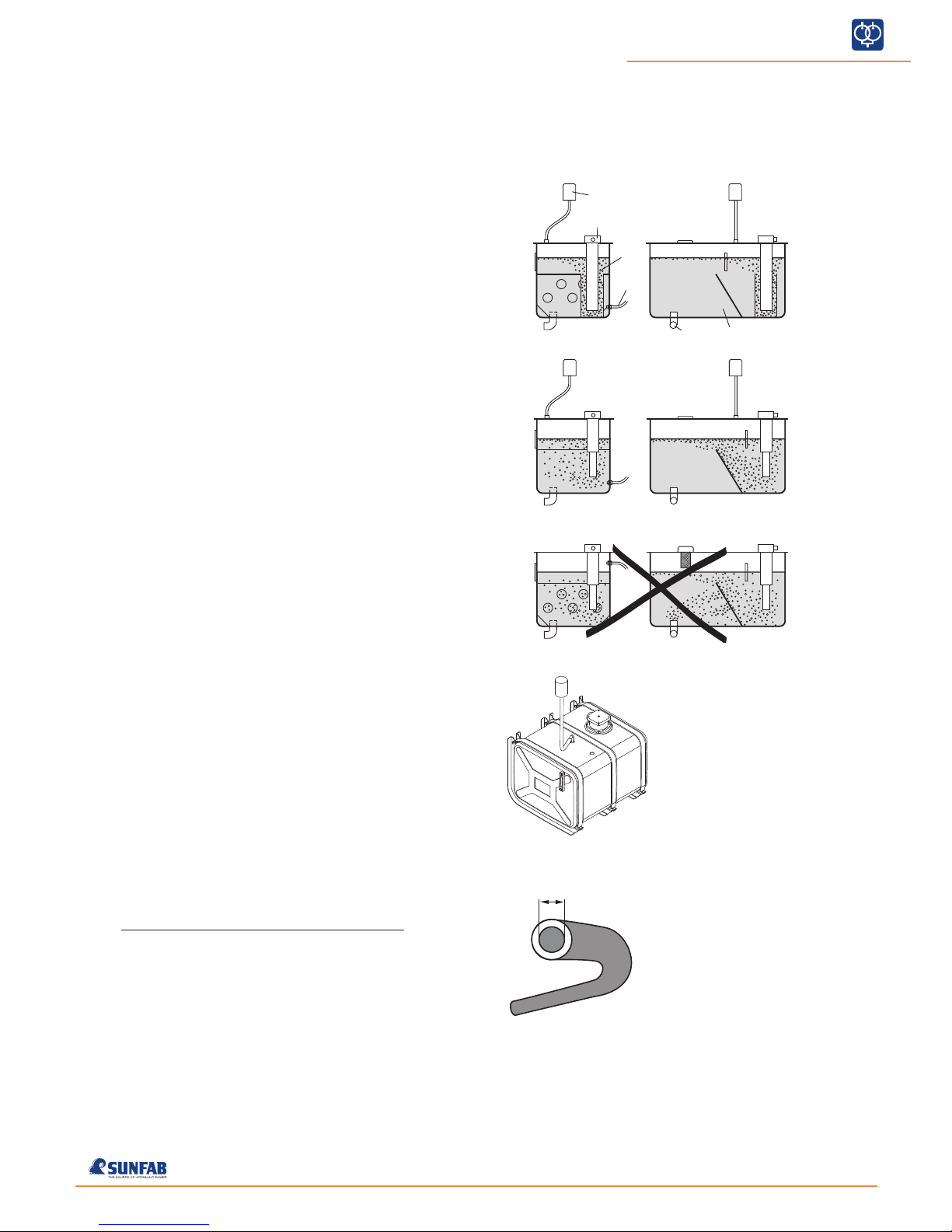
4. Not optimal designed tank for separa-
tion of air from the oil.
5. Oil tank with too small air venting area.
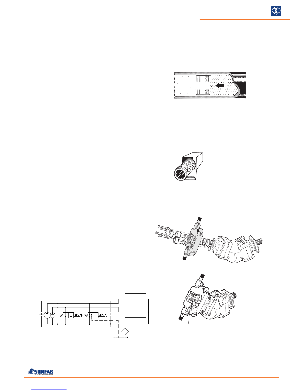
1. Too small diameter on the suction hose.
2. Crushing or restriction of the suction
hose.
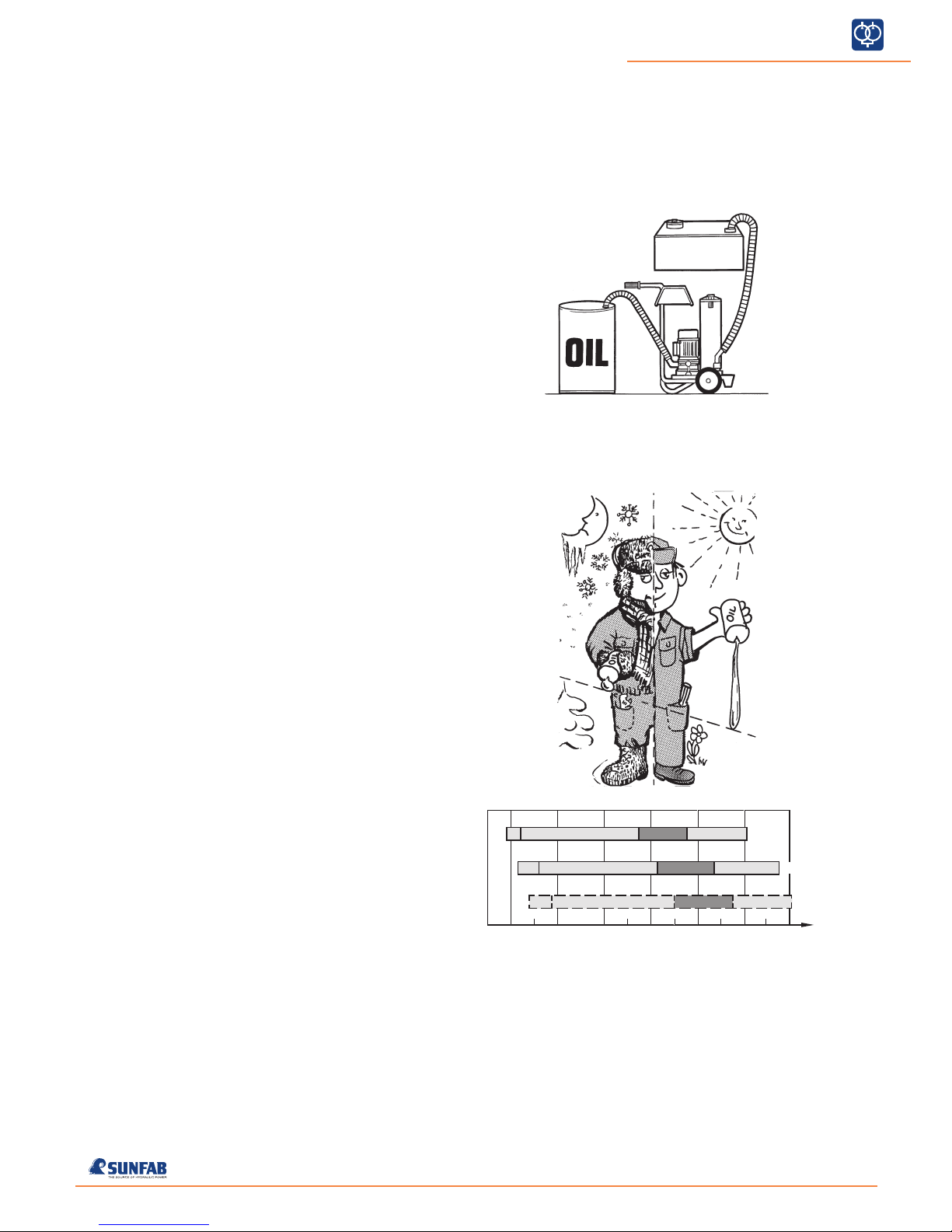
3. Oil too thick.
4. Underpressure in the oil tank.
1. Too small a diameter or restriction in
the pressure or return hoses.
2. Clogged pressure or return filter.
3. Oil flow too great.
4. Pressure relief valve tripped at too low
a pressure.
5. Oil too thin.
6. Oil tank too small.
7. Oil level too low.
8. High continuous power output.
1. Pressure relief valve tripped at too low
a pressure.
2. Defective directional control valve.
1. Pressure relief valve tripped at too
low a pressure.
2. Worn pump.
1. Too small diameter on the suction hose.
2. Crushing or restriction of the suction
hose.
3. Oil too thick.
4. Underpressure in the oil tank.
5. Worn pump.
1. Leakage from the suction connection.
2. Leakage from the shaft seal.
3. Leakage from the plugs/fittings.
1. Play on intermediate shaft.
2. Incorrect joint angle on intermediate
shaft.
3. Imbalance on intermediate shaft.
4. The universal joints are not in line with
each other.
Action
1. Vent the pump.
2. Repair the air leakage.
3. Fill with oil.
4. Replace the return filter with an oil
pipe or tank with solid baffle plate.
5. Change to a tank with a greater air
venting area.
1. Change to a suction hose with a
larger diameter.
2. Remove the restriction.
3. Change to an oil with a lower viscosity.
4. Change the air filter.
1. Change to hoses with a larger
diameter; rectify the restriction.
2. Replace the filter.
3. Lower the speed or change to a
smaller pump.
4. Adjust the valve or replace if necessary.
5. Change to an oil with a higher viscosity.
6. Change to a larger oil tank.
7. Fill with oil.
8. Fit an oil cooler.
1. Adjust the valve or replace if necessary.
2. Replace the directional control valve.
1. Adjust the valve or replace if necessary.
2. Replace the pump.
1. Change to a suction hose with a
larger diameter.
2. Remove the restriction.
3. Change to an oil with a lower viscosity.
4. Change the air filter.
5. Replace the pump.
1. Replace the O-rings and tighten the
hose clips.
2. Replace the shaft seals.
3. Replace the plugs/fittings and
tighten carefully (15 Nm).
1. Replace the intermediate shaft.
2. Ensure that the spindle on the power
take off and pump shaft are parallel.
3. Rectify the intermediate shaft.
4. Loosen and turn the spline coupling
so that the universal joints are
aligned with each other.
Troubleshooting
Check whether the flow in the pressure
hose from the pump pulsates. Oil spots
on the pump and suction hose can
indicate an air leakage.
Check the oil level in the tank.
Check whether the oil foams.
Check whether the pump cavitates.
This is noticeable through flow
pulsations and noise from the pump
stopping when the speed is lowered.
Run the pump unloaded at working
speed and measure the counter
pressure. Connect a pressure gauge to
the pressure hose close to the pump.
The pressure must not exceed 2 MPa.
Check whether the pressure rises to
the correct value when a function is run
towards the stop.
Check whether the pressure rises to
the correct value when a function is run
towards the stop.
Connect a flow meter close to the
pump. Check the flow.
1. The correct flow is obtained when
loaded.
2. Abnormally low flow obtained when
loaded.
1-5. Check whether the pump cavitates
This is indicated by the noise
stopping when the speed drops.
Check whether the noise
propagates in the hydraulic system.
6. Check whether the noise can be
heard at all speeds.
Localise the oil leakage.
Check whether the pump shakes,
despite the flow not pulsating, i.e. the
attachment does not jerk.
Fault
The equipment works
jerkily.
The equipment works
jerkily when starting and
at a high pump speed.
The oil has an abnormally
high temperature.
The equipment has a lack
of power.
The equipment runs
abnormally slowly when
loaded.
Noise from the pump.
Oil leakage from the
pump.
The pump shakes (inter-
mediate shaft assembly).
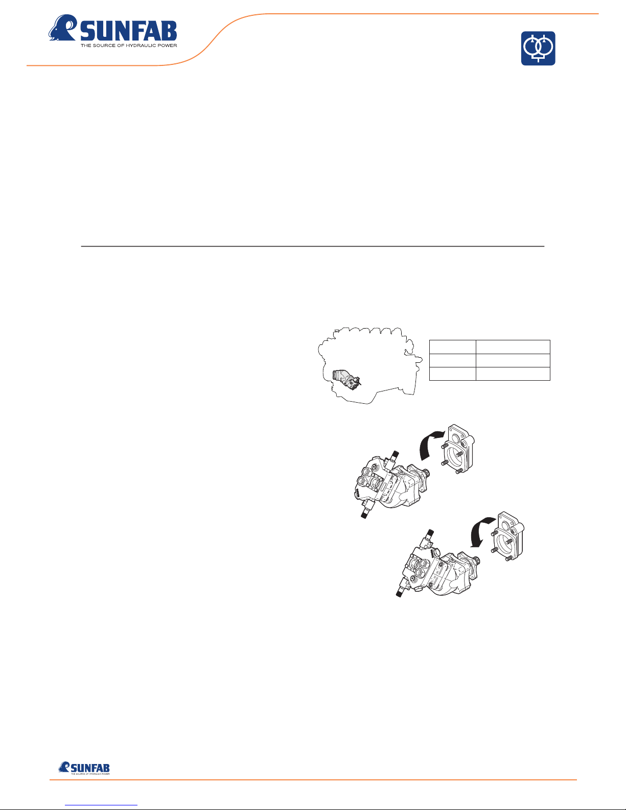
If oil leakage has occurred via a damaged shaft seal,
ensure that no hydraulic oil has entered the gearbox!