PureAire Monitoring Systems Air Check User manual

Air Check Advantage
Carbonyl Sulfide Monitor
Instruction Manual
Part number 99156 (0-100ppm)
PureAire Monitoring Systems, Inc.
1140 Ensell Road
Lake Zurich, IL. 60047
Phone: 847-726-6000
Fax: 847-726-6051
Toll-Free: 888-788-8050
E-mail: info@pureaire.net
Web: Pureairemonitoring.com

PureAire Monitoring Systems, Inc.
1
Welcome to Pure Aire Monitoring Systems
I’d like to thank you for investing in our continuous life safety and process control toxic gas
monitoring systems.
PureAire offers an unbeatable combination of experience and innovation in solving the safety
and environmental needs of our customers. We’re capable of providing small systems of a few
points to a total multi-point turnkey computerized package.
PureAire’s proprietary sensor cell technology and state-of-the-art electronics are designed to
interface with the latest distributive or PLC based control systems. We believe that our
experience, innovative products and commitment to service will satisfy your specific monitoring
needs now and in the future.
Our growth is a result of our total commitment to supporting our customers. We’re available 24
hours a day, 7 days a week to help you when you need us. Our 24 hour Emergency phone number is
847-420-3814. We can provide field service, preventative maintenance programs and training
to your technicians in the operation of our equipment. Our goal is to provide the best after sale
service and support in the industry. That’s just one way PureAire takes that extra step to
ensure your complete satisfaction.
Thank you again for investing in PureAire Monitoring Systems for your monitoring needs and
I’m proud to welcome you to our family of valued and satisfied customers.
Sincerely,
Albert A. Carrino
President

PureAire Monitoring Systems, Inc.
2
Read Before Operating
This gas monitoring system has been designed to provide long-term reliable performance. We recommend the
following basic precautions while installing, operating and maintaining this device.
▪Read this “Guide to Operation and Installation” carefully. Installation, maintenance, calibration and testing
should be performed by qualified personnel only.
▪Check if the power supply matches the specifications given in this guide and ensure that the system has been
connected properly. This monitor must be powered by a regulated 24VDC power supply.
Please ensure the proper polarity. Reversing the polarity will damage the fuse on the drive PCB.
▪After power up, please let the system equilibrate for one hour before making any adjustments. Note
the monitor may read elevated concentrations of COS during the sensor warm up. Once the cell
recovers, the monitors zero may need to be adjusted.
▪The COS monitor is designed for safety monitoring where normal use is defined as zero gas concentration
with an occasional excursion. If the monitor is continuously exposed to carbonyl sulfide or if the monitor is
exposed to very high short-term gas concentrations, it will require more frequent gas calibration or complete
sensor cell replacement, and possible a new replacement pyrolizer filament .
▪The pyrolizer filament is fragile and must never be disturbed once inside the pyro tube. Never twist the
filament inside the pyro tube.
▪The COS sensor cell has a cross sensitivity to Isopropyl alcohol, (IPA). During wipe downs it is
recommended to disable the alarm outputs to your central alarm system.
This system has a built-in pyrolizer. The pyrolizer insulation temperature can reach
150 F and can cause burns if touched. Use Caution when working near the pyrolizer.

PureAire Monitoring Systems, Inc.
3
Table of Contents
1: Introduction………………………………………………………… 4
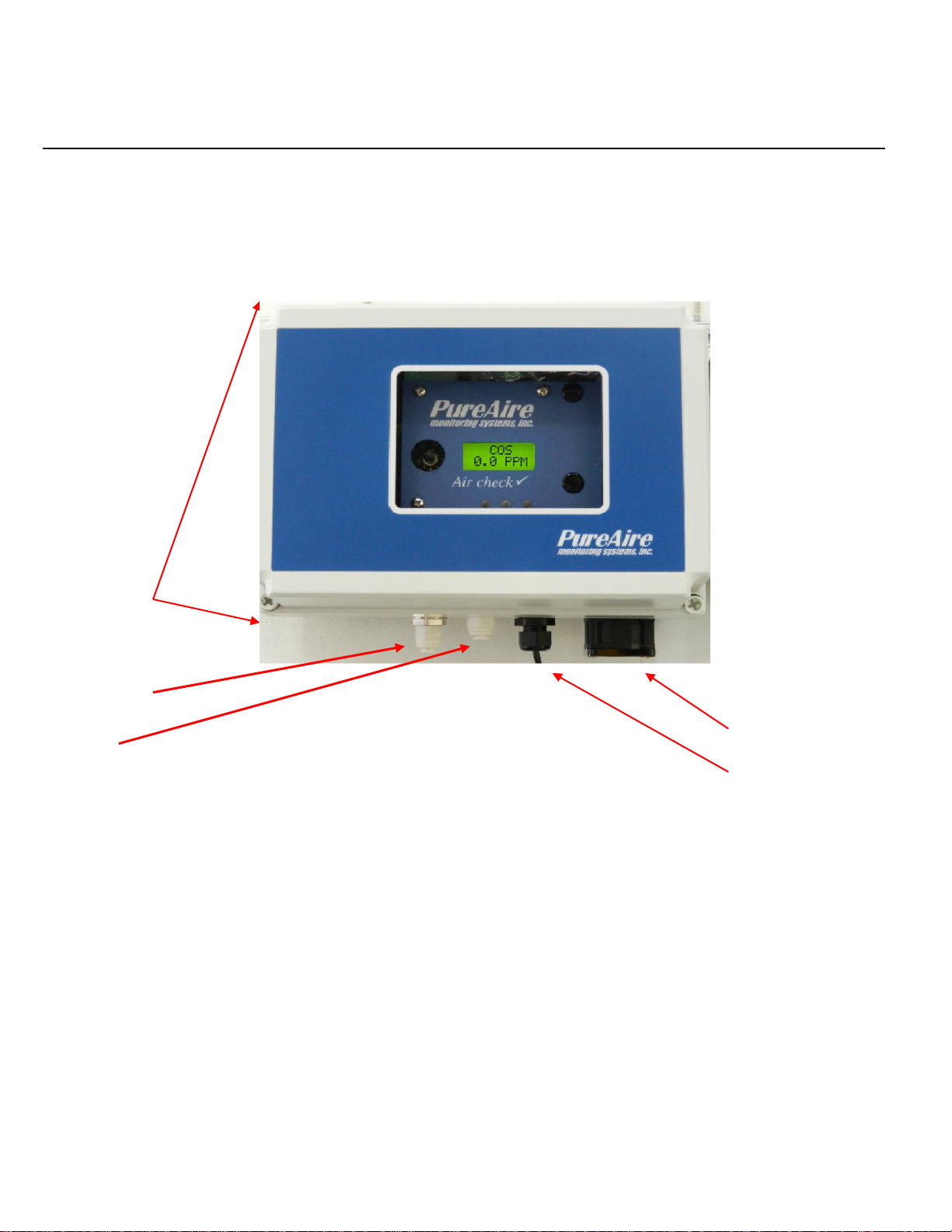
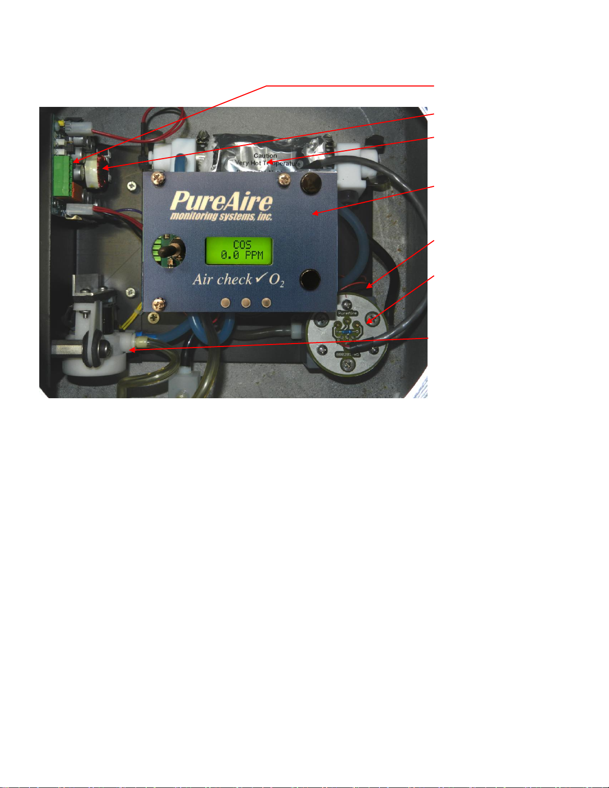
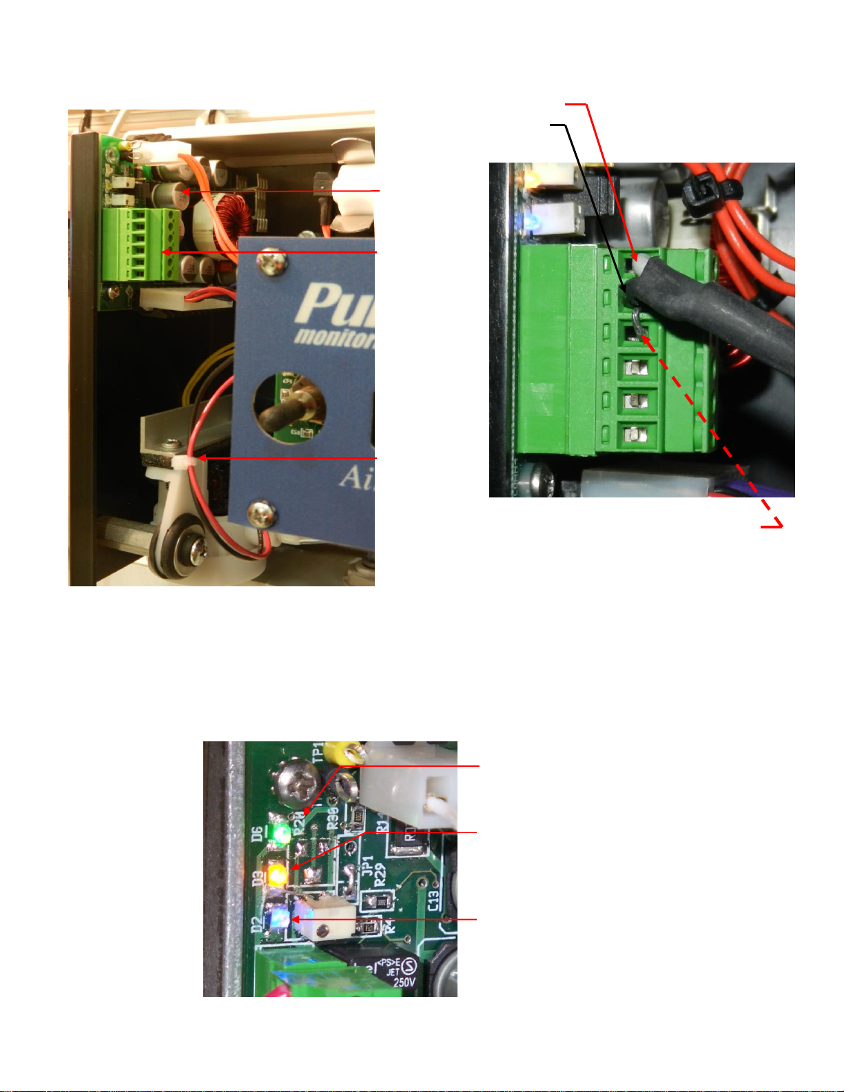
1.1 Component Identification……………………………………… 5
2: Specifications.................................................................................... 10
2.1 Performance Specifications........................................................ 10
2.2 Gas Detection System................................................................ 10
2.3 Signal Outputs............................................................................ 11
2.4 Electrical Requirements............................................................. 11
2.5 Physical Characteristics............................................................. 11
2.6 Air Check Carbonyl Sulfide Default Settings............................ 12
3: Installation........................................................................................ 13
3.1 Site Requirements...................................................................... 13
3.2 Mounting.................................................................................... 13
3.3 Sensor Installation...................................................................... 13
3.4 Wiring........................................................................................ 13
3.5 Initial Startup ............................................................................. 14
4: Air Check Carbonyl Sulfide Programming................................... 16
4.1 Control Panel Overview............................................................. 16
4.2 Joystick Operation ..................................................................... 16
4.3 Program Flow Chart................................................................... 17
4.4 Entering the Password................................................................ 18
4.5 Changing the User Password..................................................... 19
4.6 Entering the Menus.................................................................... 22
5: Maintenance & Calibration ............................................................ 33
5.1 Routine Maintenance Schedule.................................................. 33
5.2 Loss of Power Indication........................................................... 33
5.3 Sensor Cell Removal and Installation........................................ 34
5.4 System Calibration..................................................................... 36
6: Appendix........................................................................................... 40
Rev 4.05 8/2019

PureAire Monitoring Systems, Inc.
4
1: Introduction
The Air Check Carbonyl Sulfide Monitor is a compact extractive gas sampling system
designed for the continuous detection and measurement of toxic gas leaks. It is capable
of sampling over distances of up to 100 feet (33 meters).
The Air Check is a single point monitoring system built into a general purpose, Nema 2
housing that may be wall mounted. It’s designed to require as little space for installation
as possible.
The system has the following features:
▪24 VDC operation
▪Built-in pyrolizer
▪Integral digitally controlled sampling pump and flow system
▪Local digital display
▪User selectable dual level alarm and system fault relays
▪Visual dual level alarm and fault LED
▪4-20 mA output
▪Disposable electrochemical sensor cell
▪Supervised electronics monitors sensor, pyrolizer and sample pump
NOTE: The Air Check Carbonyl Sulfide enclosure is NOT rated for Class 1, Division 1
Groups B, C & D

PureAire Monitoring Systems, Inc.
5
1.1 Component Identification
1.1.1 Overall System Composition
The Air Check Carbonyl Sulfide Monitor may be integrated into the overall hazardous gas
monitoring system. As a result, it may be remotely located for the monitoring of process areas and
other environments where access to the instrument for maintenance or service may be restricted. It
may also be used as a stand-alone detection system.
Front Cover—This permits accessing the inside of the sample and control system.
Mounting Tabs—Adjustable feet designed to connect the Carbonyl Sulfide enclosure to walls or
another solid surface. There is one on each corner of the enclosure.
Cover Fastening Screws—Captive Philips head plastic screws used to fasten the front cover to the
base of the Carbonyl Sulfide monitor. There is one on each corner of the front cover.
NOTE: Please do not over tighten the screws as the Phillips head will strip.
Cable Strain Relief —This is the opening in the transmitter housing for connecting the 4-20 mA
output, 24 VDC power cable, and alarm relay wiring.
Sample Inlet —This serves as the connection for the incoming sample line.
Sample exhaust —This serves as the connection for the sample exhaust line.
Cooling Fan —This fan pushes air into the case for cooling. It exhausts on the top right side of the
case
Cooling Fan
Cable Strain Relief
Front Cover
Cover fastening
screws
(on each corner)
Mounting Tabs
(on each corner)
Sample Exhaust
Sample Inlet

PureAire Monitoring Systems, Inc.
6
1.1.2 Front View Control Panel
1. Local Digital Display —During normal operation, displays the name and
concentration of the target gas. Also displays alarm messages and
programming/calibration menus and information.
2. Joystick —Used for selecting and adjusting the built-in menus for alarm
threshold settings, relay state, alarm delay etc.
3. Alarm & Fault LED’s —These LED’s illuminate when a gas
concentration alarm or instrument fault is detected.
NOTE –The flow rate is factory set and is continuously regulated via a
built-in flow sensor. Flow rate is factory set for sampling distances
up to 100 feet. Field adjustment cannot be performed.
Local Digital
Display
Joystick
Alarm & Fault
(LED’s)
AL 2 , AL 1
& Fault

PureAire Monitoring Systems, Inc.
7
1.1.3 Internal View
1. Main Power Connector —Connector for 24VDC power input. See section 3: Installation for
more information.
2. Pyrolizer Assembly —Converts Carbonyl Sulfide gas into Carbon monoxide gas prior to
presentation to the gas sensor.
CAUTION - The pyrolizer insulation temperature is above 150 F and can cause burns if touched
3. Pyro Filament Drive PCB —Controls power to the pyrolizer filament and signals the main
control electronics if a fault occurs.
4. Control Electronics and readout —Controls the sample pump, converts the signal from the
sensor cell and sends information to the local digital display and analog /relay terminal block.
NOTE –The flow rate is factory set and is continuously regulated via a built-in flow sensor.
5. Flow Chamber —The converted gas from the pyrolizer is introduced to the gas sensor in this
chamber. Sample flow into the chamber is continually monitored. If the sample pump fails, the
system fault relay is activated.
6. Carbonyl Sulfide Sensor Cell —A disposable electrochemical sensor cell. Typical life is 2 - 3
years under normal operating conditions.
7. Sample Pump —This internal sample pump is used to draw the gas sample from the area into
the pyrolizer and flow chamber.
8. Inlet & Exhaust —These are connections for the incoming gas sample and outgoing exhaust
sample
Main Power Connector
Pyro Filament Drive PCB
Pyrolizer Assembly
Control Electronics / Readout
Flow chamber
(located under the sensor cell)
Carbonyl Sulfide sensor cell
Sample Pump

PureAire Monitoring Systems, Inc.
8
1.1.4 Transmitter Interior
1. Power / Analog Terminal Block —This terminal block is where the 24VDC power and
4-20 mA analog output connection is made.
1.1.5 Alarm Relay Board
1. Power / Analog
output Terminal Block
Fuse*
(Field replaceable)
Common
Common
mA output
+ 24 VDC
+ 24 VDC
Flow Sensor
Pump
Connector
Alarm Relay 2 Alarm Relay 1 Fault Relay
NC C NO NC C NO NC C NO
Remote
Reset
Sensor cell
connector
(terminated at the
factory)
*Fuse –A new fuse can be purchased directly from Digikey.com.
Their part number is F5689CT-ND

PureAire Monitoring Systems, Inc.
9
Main power connection
(Terminated by PureAire or can
be terminated by the customer
when using their own power
supply)
Status LED’s
Green Power LED.
Confirms Power is being supplied to
the monitor.
Yellow Status LED.
Confirms the filament drive board is
operational.
Blue Fault Status LED.
Flashes to indicate various system
faults.
When not in fault the Blue LED
remains illuminated continuously
Pump and Pyrolizer Drive Assembly
Pyrolizer
Drive Board
Main 24VDC
Power
Connector
Sample
Pump
+ 24VDC Pin 6
Common Pin 5
NOTE: DO NOT Remove the shorting
pin connected to pins 5 and 4.

PureAire Monitoring Systems, Inc.
10
2: Specifications
NOTE: Due to our commitment to continual product improvement, all specifications are subject to
change without notice.
2.1 Performance Specifications
Models: Air Check Carbonyl Sulfide Monitor
Sensor Type: Disposable electrochemical cell.
Response Time: Within 60 seconds to T90.
Repeatability: ±10% of full scale.
Fault Indicators: Loss of VDC power (4 mA signal drops to 2, system fault alarm relay de-energizes);
Loss of sensor signal (local visual alarms, system fault alarm de-energizes);
Loss of sample pump (4 mA signal drops to 2, system fault alarm relay de-energizes)
Loss of Pyrolizer filament (4 mA signal drops to 2, system fault alarm relay de-energizes)
Operating Temp: 14° to 86°F (0° to +30°C); consult PureAire for lower or higher operating temperatures.
Humidity: Typically, 20 to 95% RH;
Warranty: The warranty is limited to repairing or replacing the instrument or part thereof for a period
of one (1) year after shipment, when in our opinion, the repair or replacement is covered by
this warranty. Any defective equipment must be returned prepaid to the PureAire Monitoring
Systems, Inc. factory or service. Field service is not included. This warranty does not cover
components that are expendable or consumable in normal use and thus have an unpredictable
life such as batteries, fuses, sample pumps, filaments and sensor cell.
2.2 Gas Detection System
Type: Proprietary disposable electrochemical gas sensor.
Sensor Life: 2-3 years under normal conditions.
Detectable Gas: Carbonyl Sulfide Standard Range 0-100ppm
11

PureAire Monitoring Systems, Inc.
11
2.3 Signal Outputs
Local Display: Digital display calibrated for Carbonyl Sulfide. The range is stated on the model label and can also
be accessed via the joystick on the front panel.
Analog Output: DC 4-20 mA
Relay Output: Dual level user selectable alarm relays and one fault relay
Rated, 2amps @ 30VDC; 2amps @ 250VAC
2.4 Electrical Requirements
Power: 24 VDC external power. NOTE: Must be a regulated 24VDC Power Supply
Consumption: 2.0 amps.
2.5 Physical Characteristics
Dimensions: 10” W x 7.0” H x 7.0” D inches;
254 x 178 x 178 mm
Weight: 10 pounds (4.5 kg)
Enclosure Type: NEMA 4X wall mounted enclosure. Not for use in hazardous environments.
(Please contact PureAire for information on our Class 1 explosionproof enclosure)

PureAire Monitoring Systems, Inc.
12
2.6 AirCheck Carbonyl Sulfide Default Factory Settings
The Air Check Carbonyl Sulfide Monitor is shipped with factory defaults for the alarm relay settings. The
following are the factory defaults:
NOTE:The built-in relay settings may be changed by the user in the field. Refer to Section 4.5
** NOTE: The LED indicators on the front panel are connected directly to the alarm relays.
Menu Function
Factory Default
Menu Defined
Alarm Thresholds
Alarm 1 = 5.0ppm
Alarm 2 = 10.0ppm
At what level do you want to alarm?
Set Alarm Threshold
Polarity
Alarm 1 = Normal
Alarm 2 = Normal
Do you want to alarm at a level
higher, (normal) or lower, (inverted)
than the alarm threshold?
Alarm Delay
Alarm = 5 seconds
How long do you want to wait until
the alarms activate?
Zero Suppression
2 ppm
At what level do you want to see the
initial gas concentration reading?
Set Alarm Hysteresis
Alarm 1 = 0.0 ppm
Alarm 2 = 0.0 ppm
For use when using the monitor for
control. It is recommended to set both
alarm hysteresis at 0.0ppm
Relay Latching
Alarm 1 = Non-latching
Alarm 2 = Non-latching
Do you want the alarm to
automatically reset? (non-latching) or
do you want to manually reset the
alarm? (latching)
Format Relay - LED
State **
Alarm 1 = Normal
Alarm 2 = Normal
Fault = Normal
Do you want the relays to energize,
(normal) or de-energize, (fail safe)
when the alarm activates?

PureAire Monitoring Systems, Inc.
13
3: Installation
3.1 Site Requirements
The Air Check Carbonyl Sulfide monitoring system should be mounted in an area free of vibration and electrical noise or
interference. If possible, avoid areas with continuous high temperatures or relative humidity.
The unit should be installed in a location where gas leaks are likely to occur or where released gases may accumulate.
Airflow within the monitored area, the characteristics of the target gas (lighter or heavier than air), and the position of
workstations and personnel should all be considered in determining the most suitable installation location.
Allow enough space around the instrument to permit access for maintenance and calibration.
NOTE: The Air Check Carbonyl Sulfide Monitor is NOT designed for installation in hazardous
areas.
3.2 Mounting
The Air Check is designed primarily for wall mounting and should be installed no closer than 36 inches (915 mm) above
floor level. If mounted outdoors, keep direct sunlight off the enclosure.
3.3 Sensor Installation
The Carbonyl Sulfide sensor cell is connected to the flow chamber at the factory. Please do not disturb
the sensor during installation of the monitor.
3.4 Wiring
3.4.1 24 VDC Power
Connect the 24 VDC power cable to the terminal block located on the inside of the instrument. The
terminal connections are as follows: (Pin 6) +24V, (Pin 5) Common, and (Pin 4) shield. A three-
wire shielded cable (3-conductor, 18 AWG stranded shielded) General Cable #E2203S.30.86 or
equivalent should be used for the connection. The total length of the cable between the gas detector
and controller must not exceed 0.62 miles (1 km).
CAUTION: The Air Check Carbonyl Sulfide Monitor must only be powered using a
regulated 24VDC Power Supply. Failure to use a regulated 24VDC power supply will void the
warranty.
The 24 VDC power in connections are made on the 6 pin terminal connection located on the Power
Supply PCB. These connections are made as follows:
Pin #
Connection
6
DC + 24V
5
Common
4
Shield

PureAire Monitoring Systems, Inc.
14
3.4.2 Alarm Relays
The Air Check monitor incorporates two gas concentration alarm relays and one system fault relay.
These relays may be wired for normally open (N.O.) or normally closed (N.C.) operation and are
rated as follows: Rated, 2amps @ 30VDC; 2amps @ 250VAC. See page 9.
3.5 Initial Startup
Once installation of the gas detector has been completed, it is ready for startup. The following
procedures should be performed before putting the instrument into operation:
1. Check the integrity of all wiring. Confirm the power polarity.
2. Run any sample tubing from the monitor to the risk site.
NOTE: PureAire recommends the use of polypropylene sample tubing with the
dimensions of 1/4” OD by 3/16” ID. The total length of tubing should not exceed
100 feet.
3. Apply 24 VDC power to the Power Supply PCB board. The sample pump and pyrolizer heater
will operate.
NOTE: The Air Check requires a regulated 24VDC power supply
CAUTION - The pyrolizer insulation temperature is above 150 F and can cause burns if
touched.
The monitor is now ready for power up. On power up, the monitor will immediately start a 2-minute countdown and the
green and yellow LEDs will be illuminated next to the power connector. It will then display COS on the top line and
countdown from 120 to 0 and display WARM on the bottom line. Also, the Yellow Fault LED will be illuminated on the
front panel.
Pyrolizer & Pump Drive Board
Flow and Pyro Factory Set
Potentiometers Do Not adjust
Status LED’s
Power Connector
Pin 6 +24 VDC
Pin 5 Common
Pin 4 Shield
Pins 1, 2 and 3 are not used.
Fuses
Plug In type F3 F1 F2

PureAire Monitoring Systems, Inc.
15
After the 2-minute countdown, the blue LED will illuminate and “Pyrolizer Heater Fault” will scroll on the top line, F02 00
will display on the bottom line and the Yellow Fault LED will remain illuminated.
Approximately 30 seconds later, the “Pyrolizer Heater Fault” and F02 fault message and will clear and COS will display
on the top line, a ppm gas concentration will display on the bottom line of the digital display and the Yellow Fault LED will
turn off.
NOTE: After power up, please let the system equilibrate for one hour before making any
zero and span adjustments. The Carbonyl Sulfide sensor may read a high ppm gas
concentration on startup. The sensor’s zero will stabilize during this warm period.
NOTE: The monitor is designed for continuous 24-7-hour operation. Do not power down
the monitor unless you intend to store the monitor. Cycling the monitor on and off will
diminish the performance of the Carbonyl Sulfide readings.
After the warmup, if the monitor is reading a positive PPM, and you are sure that it is not being exposed to Carbonyl Sulfide
then re adjust the zero. Refer to section 5.4.3.
3.5.1 Pump Adjustment
The Air Check Carbonyl Sulfide Monitor has a built in digitally controlled flow-controlled sample
pump. The pump flow is set at the factory and should not require adjustment. It has a range to
accommodate tubing lengths up to 100 feet. Flow rate is between 0.2 and 0.25 cc/min. If flow
adjustment is necessary, please contact PureAire.

PureAire Monitoring Systems, Inc.
16
4: Air Check Monitor Programming
The Air Check Carbonyl Sulfide Monitor is supplied with user selectable settings to adjust the alarm settings, 4 and
20mA output and minor sensor adjustments. The settings are arranged in menus that are accessed by moving the
joystick. To access the menus a factory set password is used.
NOTE: The Air Check Carbonyl Sulfide Monitor will continuously monitor Carbonyl Sulfide while accessing the
menus. The alarm, fault relays and mA output are all active and on line while making any changes to the menus.
4.1 Control Panel Overview
All instrument configuration and operational programming is performed from the front panel of the Air Check Monitor using
the joystick.
4.2 Joystick Operation
The Air Check Carbonyl Sulfide monitor uses a 4-position joystick with a center pushbutton for selecting menus and
changing values. The joystick is programmed to standard protocol as follows:
NOTE: The joystick has a built-in delay to prevent accidental tampering of the menus. Deliberate entries
are required.
P
r
e
v
i
o
u
s
s
Plus –Pushing the joystick in this direction increases the value
Minus –Pushing the joystick in this direction decreases the value
Next –Pushing the joystick in this direction moves you to the next level of the menu hierarchy.
Previous –Pushing the joystick in this direction takes you out to the last level of menu hierarchy.
Enter –Pushing the joystick directly in the center enters the information into the microprocessor
NOTE: The joystick has four other positions that are only used to only access factory menus. A separate
factory password is required obtain entry.
Plus
Minus
Previous
Next

PureAire Monitoring Systems, Inc.
17
4.3 Program Flowchart

PureAire Monitoring Systems, Inc.
18
4.4 Entering the Password
The Air Check Carbonyl Sulfide monitor is supplied with a factory set password to prevent unauthorized access to
the menus. The Password is 557.The following explains how to enter the password.
1. Push the joystick once to the right. Enter Password will scroll on the first line of the digital display. The second line
will still display the current oxygen level.
2. Push the joystick again once more to the right to enter the input screen. The letter A will appear and flash.
NOTE: The display has characters that start with A through Z and 0 through 9.
Pushing the joystick up or down will permit you to scroll through the
alphanumeric characters.
3. Push the joystick up or down to enter the first digit. The display is an alphanumeric display and toggles from A
through Z followed by 0 to 9. The character to be entered will flash.
4. Push the joystick again to the right to select the second entry. Push the joystick up or down to select the second digit.
The character being entered will flash and the first character entered will remain lit.
5. Push the joystick again to the right to select the third entry. Push the joystick up or down to select the third and final
digit. The character being entered will flash and the first and second characters entered will remain lit. You are now
ready to enter the 3-digit password.
..Enter password…
2
0
.
9
%
A
2
0
.
9
%
5
2
0
.
9
%
55
2
0
.
9
%
557
2
0
.
9
%

PureAire Monitoring Systems, Inc.
19
6. Push the joystick in the center to enter the password. If you entered it correctly the display will scroll Password OK.
NOTE: If an incorrect password has been entered, the display will indicate Password Failed. Push the joystick to the left
to access the monitoring mode. From this mode you can reenter the password again.
4.5 Changing the User Password
The Air Check Carbonyl Sulfide monitor is supplied with a factory set password to prevent
unauthorized access to the menus. The user can change this password and the following explains
how to change the password.
1. Push the joystick down to access the Manage Passwords Menu. Manage Passwords will scroll on the first line of
the digital display. The second line will still display the current oxygen level.
2. Push the joystick to the right to enter the input screen. Enter New User Password will scroll on the first line of the
digital display
3. Push the joystick to the right to enter the input screen. The letter A will appear and flash.
NOTE: The display has characters that start with A through Z and 0 through 9.
Pushing the joystick up or down will permit you to scroll through the
alphanumeric characters.
...Password OK……
2
0
.
9
%
..Manage Passwords…
2
0.
9
%
…Enter New User Password…
0.0 PPM
A
2
0
.
9
%
This manual suits for next models
1
Table of contents