manuals.online logo
Brands
  1. Home
  2. •
  3. Brands
  4. •
  5. PureEdge Lighting
  6. •
  7. Cables And Connectors
  8. •
  9. PureEdge Lighting Nova NCM-SP Series User manual

PureEdge Lighting Nova NCM-SP Series User manual

1
SAVE THESE INSTRUCTIONS!
- This product is ETL listed.
- This product is ceiling mount.
- The NCM-SP-_ and SP1 connectors physically connect
two NC_M-_ Nova Ceiling Modular Channels together and
conduct the power from a remote power supply powering
up to two channels.
IMPORTANT INFORMATION
1718 W. Fullerton Chicago, IL 60614
Ph: 773.770.1195 ● Fax: 773.935.5613
www.PureEdgeLighting.com ● [email protected]
© 2016 PureEdge Lighting. All Rights Reserved.
Doc # 904-NCM-SP_01
Installation Instructions for Nova Ceiling Modular Straight Power
Connector
NCM-SP_-_
Section One: 4" Square Split Canopy
NOTE: Omit this section if using 1" Rectangle Canopy. See
Section Two.
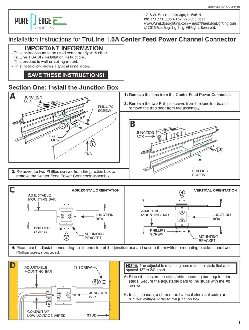
1: Feed the low voltage wires from the power supply through
the crossbar center hole.
2: Mount the crossbar to the junction box holes using two
#8-32 screws.
3: Complete installation by following steps in Section Three.
A
#8-32
SCREW 2
CROSSBAR
JUNCTION
BOX
NOTE: Ensure remote power supply wires are present in the
junction box. Refer to instructions provided with the power
supply.
1
Section Two: 1" Rectangle Canopy
1: Mount each adjustable mounting bar to one side of the
junction box (mounts to any side of the housing depending
on the orientation of the channel) and secure them with the
mounting brackets and Phillips screws provided.
BVERTICAL ORIENTATION
HORIZONTAL ORIENTATION
1
1
JUNCTION
BOX
ADJUSTABLE
MOUNTING BARS
MOUNTING
BRACKET
SCREW
JUNCTION
BOX
NOTE: Omit this section if using 4" Square Split Canopy.
C
JUNCTION
BOX
SCREW
ADJUSTABLE
MOUNTING BARS
JOIST
3
2
2: Select the location between two joists to mount the
junction box.
3: Place the lips of the adjustable mounting bars against the
joists. Secure the adjustable bars to the joists with the #8
screws.
NOTE: The adjustable mounting bars mount to joists that are
spaced 14.5"-25" apart.
NOTE: Ensure the opening of the junction box is aligned with
the center of the desired fixture location. If necessary, adjust the
junction box location by loosening the screws and sliding the
junction box to the proper location. Tighten the Phillips screws
after adjusting.
4: Remove a knockout to install a conduit into the junction box.
5: Install conduit(s) (if required by local electrical code) and
run low-voltage 24VDC power wires coming from the remote
power supply to the junction box.
NOTE: Ensure remote power supply wires are present in the
junction box. Refer to instructions provided with the power
supply.
D
CONDUIT
JUNCTION
BOX
4
5
E6: Mark a rectangle shape on the drywall where the junction
box opening will be located depending on the selected
position.
7: Cut out the marked rectangle opening, using a "Dremel
Multi-Max" with the "wood & drywall" cutting bit.
8: Install & finish drywall.
9: Complete installation by following steps in Section Three.
RECTANGLE
OPENING
DRYWALL
DREMEL
MULTI-MAX
WOOD & DRYWALL
CUTTING BIT
6
7
10: Optional: Use the Goof Plate if the junction box opening
has imperfection/ jagged edges. Install the provided
goof plate (paint to match prior) with the two screws.
F
SCREW
GOOF PLATE
(ONLY USE IF JAGGED
PLASTER EDGE,
PAINT TO MATCH)
PLASTER THE EDGE OF
THE JUNCTION BOX
JUNCTION
BOX OPENING
EDGE
10
2
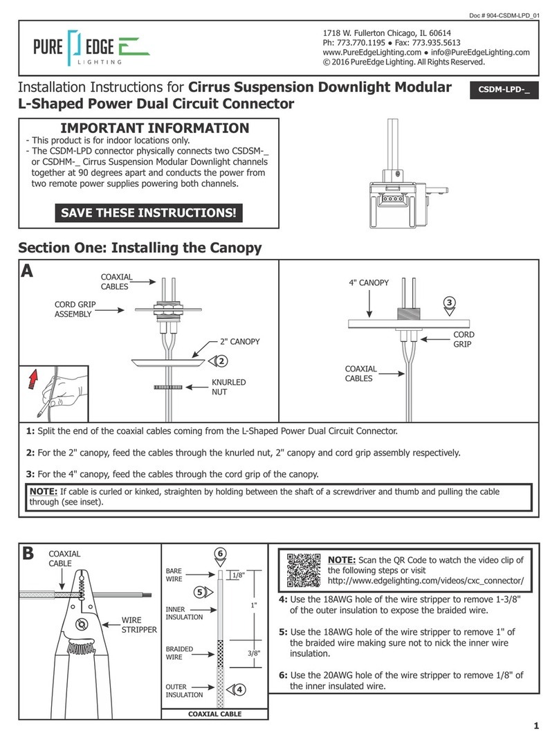
Section Three: Connecting Channel Sections
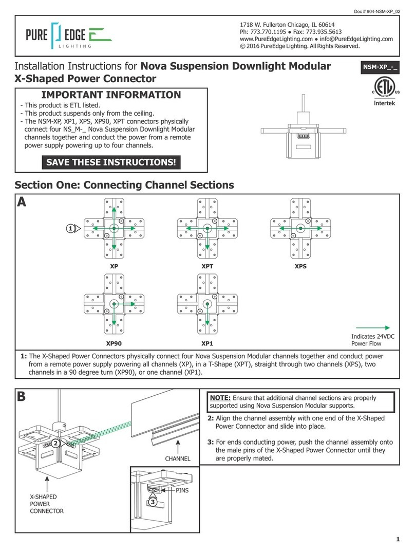
2: Align the channel assembly with the Straight Power
Connector and slide into place.
3: For ends conducting power, push the channel assembly onto
the male pins of the Straight Power Connector until they
are properly mated.
H
3
PINS
3
4: Secure the channel by tightening the four #4-40 set screws
using a 0.05" Allen wrench.
5: Repeat steps 2 through 4 for the other end of the Straight
Power Connector.
6: Install the lenses and optional louvers to the assembled
channel (refer to the instructions provided with the channel).
I
#4-40 SET
SCREW
CHANNEL
STRAIGHT POWER
CONNECTOR
SP
SP1
1: The Straight Power Connectors physically connect two Nova
Ceiling Modular Channels together and conduct the power
from a remote power supply powering two channels (SP) or
one channel (SP1).
INDICATES 24VDC
POWER FLOW
2
5
G
4
J
7: Connect the low voltage +24VDC power supply wire to the
red wire of the Straight Power Connector with a wire nut.
8: Connect the low voltage -24VDC power supply wire to the
black wire of the Straight Power Connector with a wire nut.
9: If necessary, snap the wire management clip to the
channel to hold the wires in place.
10: Place all wire nut connections inside the junction box.
11: Refer to the instructions provided with the channel to
complete the installation.
JUNCTION
BOX 7
8
10
CHANNEL
WIRE
MANAGEMENT
CLIP
9
4
#4-40
SCREW
CANOPY
CANOPY
#4-40
SCREW
K12
12: For 4" Square Split Canopy installations, place each canopy
piece against the fixture and align the canopy holes with
the crossbar holes. Secure the canopy pieces in place with
the two #4-10 screws and 1/16" Allen wrench provided.

Other PureEdge Lighting Cables And Connectors manuals

PureEdge Lighting Nova NSUDM-CAP User manual

PureEdge Lighting

PureEdge Lighting Nova NSUDM-CAP User manual

PureEdge Lighting TruLine 1.6A User manual

PureEdge Lighting

PureEdge Lighting TruLine 1.6A User manual

PureEdge Lighting NSM-XP Series User manual

PureEdge Lighting

PureEdge Lighting NSM-XP Series User manual

PureEdge Lighting TruLine 1A User manual

PureEdge Lighting

PureEdge Lighting TruLine 1A User manual

PureEdge Lighting Cirrus Suspension Downlight Modular CSDM-LPD... User manual

PureEdge Lighting

PureEdge Lighting Cirrus Suspension Downlight Modular CSDM-LPD... User manual

Popular Cables And Connectors manuals by other brands

Philips SDW5214O Specifications

Philips

Philips SDW5214O Specifications

Redarc KIT24 quick start guide

Redarc

Redarc KIT24 quick start guide

Datwyler HDPS Installation instruction

Datwyler

Datwyler HDPS Installation instruction

SBE SBE 37 SM/SI V3 quick guide

SBE

SBE SBE 37 SM/SI V3 quick guide

ELCART 42/12490-00 user manual

ELCART

ELCART 42/12490-00 user manual

Kramer HDBT installation guide

Kramer

Kramer HDBT installation guide

ATEN VanCryst VS172 user manual

ATEN

ATEN VanCryst VS172 user manual

RFDesign RFDMX user manual

RFDesign

RFDesign RFDMX user manual

Greenlee 39905 Operation, service and parts instruction manual

Greenlee

Greenlee 39905 Operation, service and parts instruction manual

S6 HVS-6204 user manual

S6

S6 HVS-6204 user manual

VPC ICON user manual

VPC

VPC ICON user manual

WEG CVW-300 Assembling Guide

WEG

WEG CVW-300 Assembling Guide

Lenze L-force EYF A Series Mounting instructions

Lenze

Lenze L-force EYF A Series Mounting instructions

Philips SWV4000S/10 user manual

Philips

Philips SWV4000S/10 user manual

Staubli CombiTac Assembly instructions

Staubli

Staubli CombiTac Assembly instructions

Gefen TOOLBOX GTB-HD4K2K-148C-BLK user manual

Gefen TOOLBOX

Gefen TOOLBOX GTB-HD4K2K-148C-BLK user manual

M-system 18KBXC-K5 instruction manual

M-system

M-system 18KBXC-K5 instruction manual

GoMax Electronics SP-4004Z-PT user manual

GoMax Electronics

GoMax Electronics SP-4004Z-PT user manual

manuals.online logo
manuals.online logoBrands
  • About & Mission
  • Contact us
  • Privacy Policy
  • Terms and Conditions

Copyright 2025 Manuals.Online. All Rights Reserved.