3
2
JOINER
BAR
CENTER FEED
POWER CONNECTER
CHANNEL
M3 SET
SCREW
CHANNEL
POWER
CONNECTOR
10
9
11
6" FIXED
JAB SAW
7
2
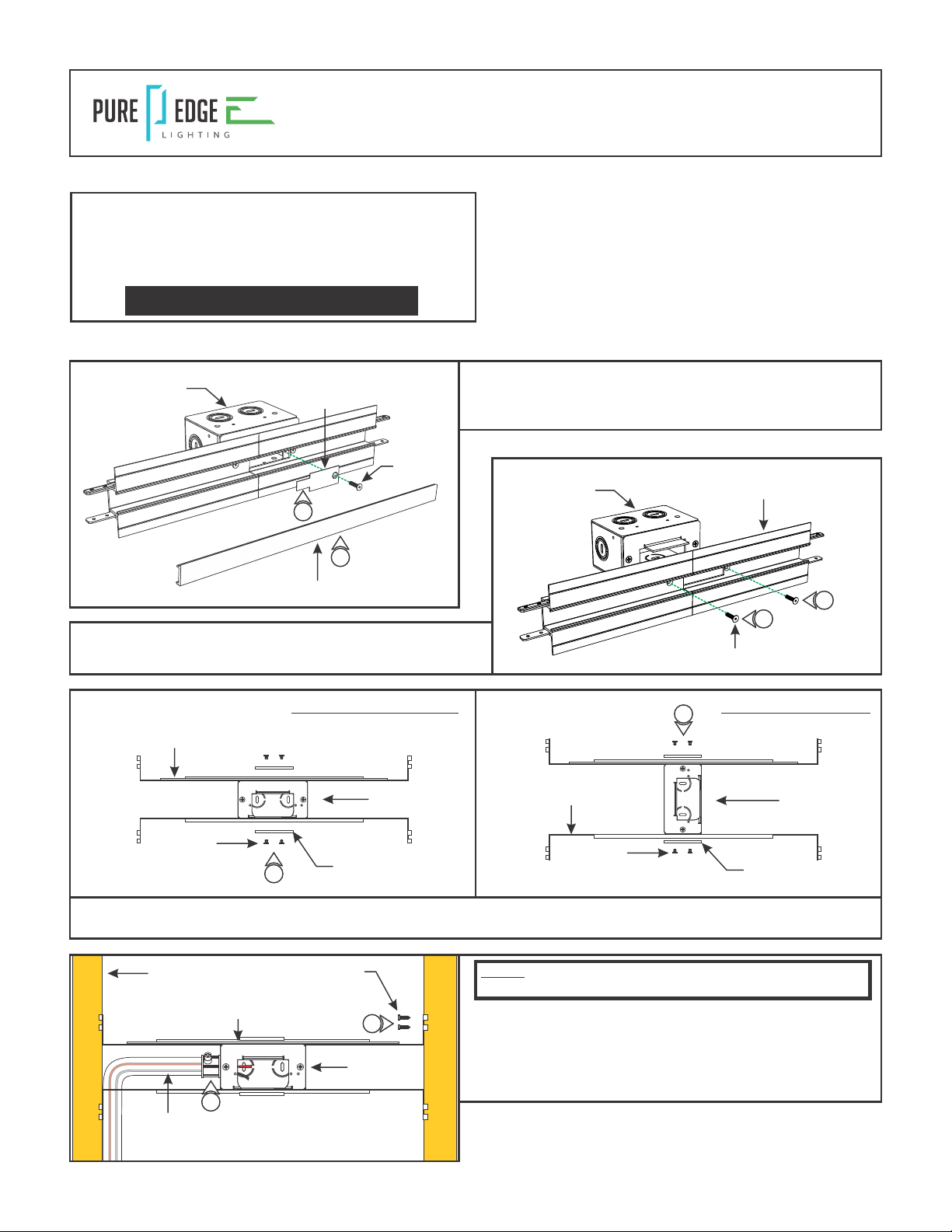
Section Two: Prepare and Install the Center Feed Power Connector
2: Slide a channel onto the joiner bars and tighten the
remaining M3 set screws with a 1.5mm Allen wrench.
3: Repeat step 2 for the other end of the Center Feed Power
Channel Connector.
1: Refer to Section One in the TruLine 1A Channel and Lens
instructions to measure and cut the channel and lens before
continuing.
CUT
E7: Cut a section of drywall using a 6" fixed jab saw or other
appropriate tool to expose the mounting plate area.
8: If using the Snap & Light connector (LC-SLC) with standard
Soft Strip, cut the end of the power cord and discard the
unused connector. Strip the ends of the wires.
8
+24VDC
-24VDC
SNAP & LIGHT
CONNECTOR
CUT
8
NOTE: Remote power supply wires must be present in junction
box. Refer to instructions provided with power supply.
9: Connect the red low voltage wire of the power supply to the
red wires of either the B90 connector or Snap & Light
connector with a wire nut.
10: Connect the black low voltage wires of the power supply to
the black wires of the same connector with a wire nut.
11: Place all wire nut connections inside the junction box.
F
G
H
I
1
CHANNEL
LENS AND CHANNEL LENGTH
LENS
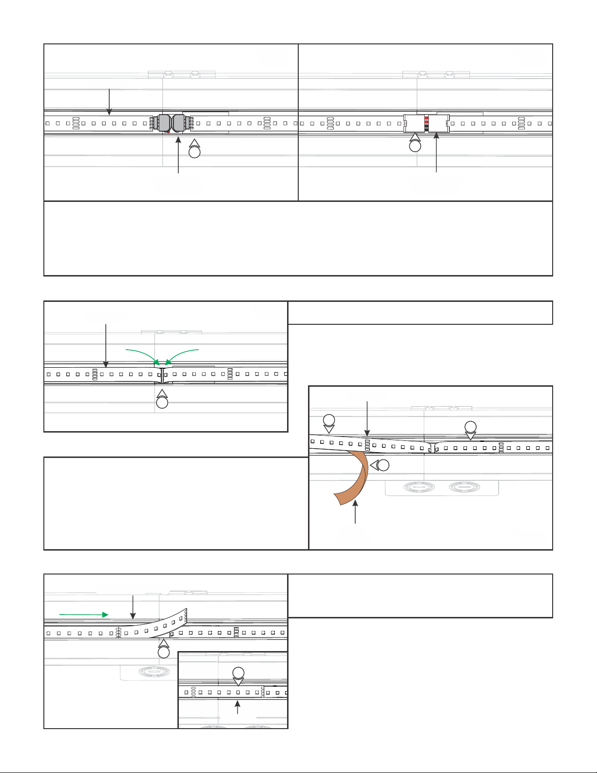
CAUTION: Unroll the entire LED strip from the reel and use
the power connector to power the strip making sure there is
no outage before continuing with the installation. Afterwards,
carefully roll the LED strip loosely back into the reel.