#4-40
SCREW
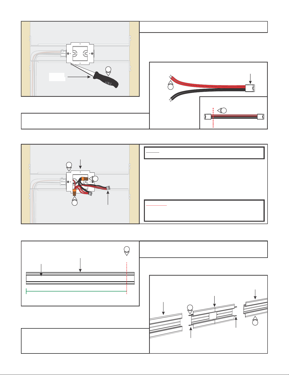
Section Three: Install the LED Soft Strip with B90 Connectors (side mount)
4: Attach the assembled trap door frame to the junction box
using the #4-40 screws.
NOTE: Refer to Section Three in the TruLine 1.6A Channel and
Lens instructions to plaster before continuing.
1: Insert the male-to-male power adapter to each power
connector.
2: Connect the L-Shaped Flexible Power Connectors to each
male-to-male power adapter.
3: Repeat steps 1 and 2 for additional power connectors.
L-SHAPED
FLEXIBLE
CONNECTOR
POWER
CONNECTOR
NOTE: Center Feed Power Channel could feed the strip one or
both directions. When using to feed one direction, discard the
other connectors.
3
TRAP DOOR
FRAME
J
K
L
4
SIDE
MOUNT
SIDE
MOUNT
1
4
L-SHAPED
FLEXIBLE
CONNECTOR
POWER
ADAPTER
2
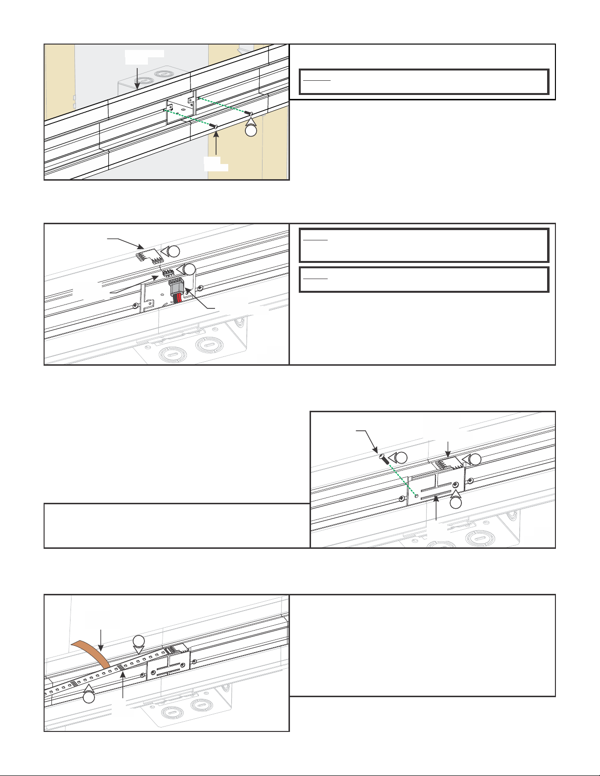
4: Place each assembled power connection into the channel
where the LED Soft Strip will be installed.
5: Replace the trap doors and secure using the #4-40 screws.
#4-40
SCREW
TRAP
DOOR
5
5
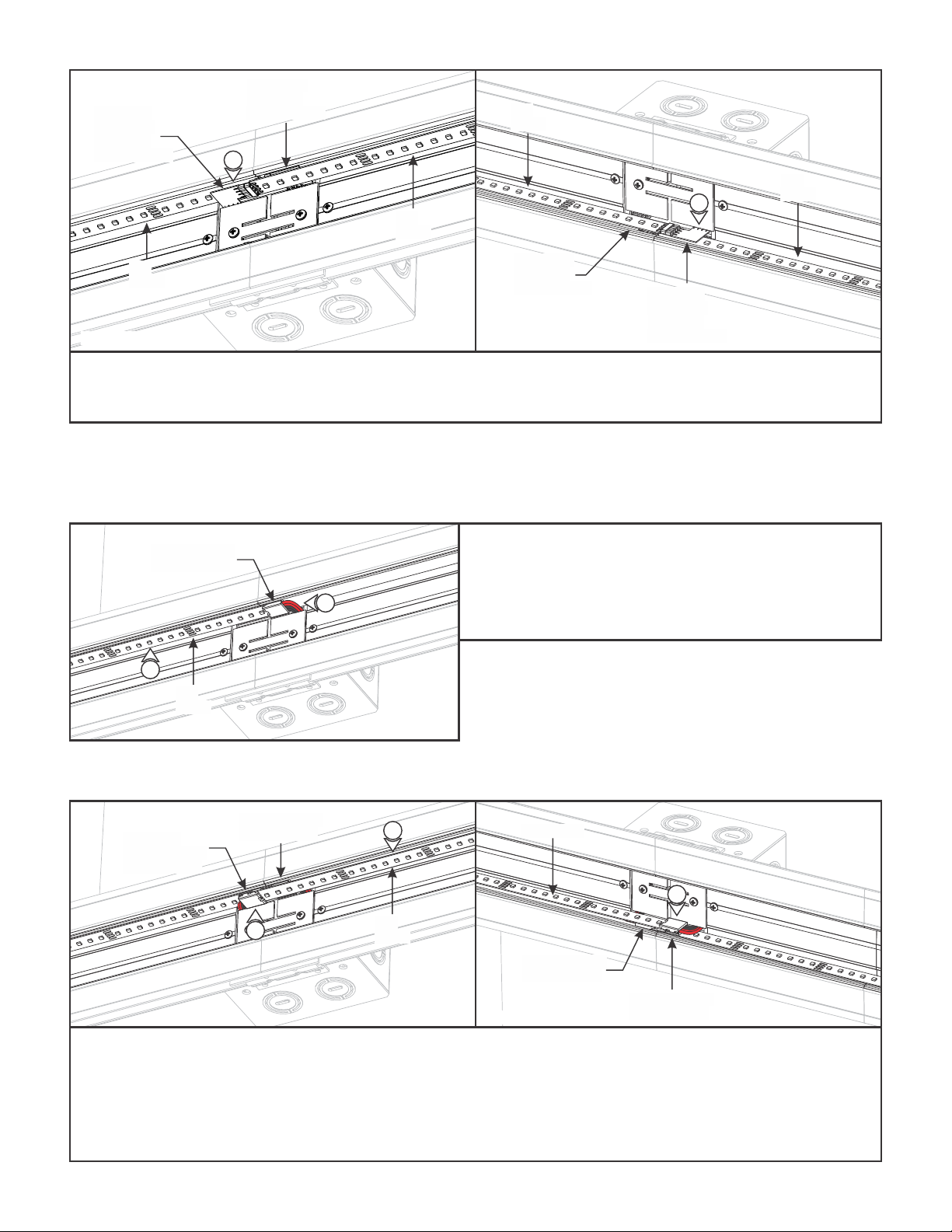
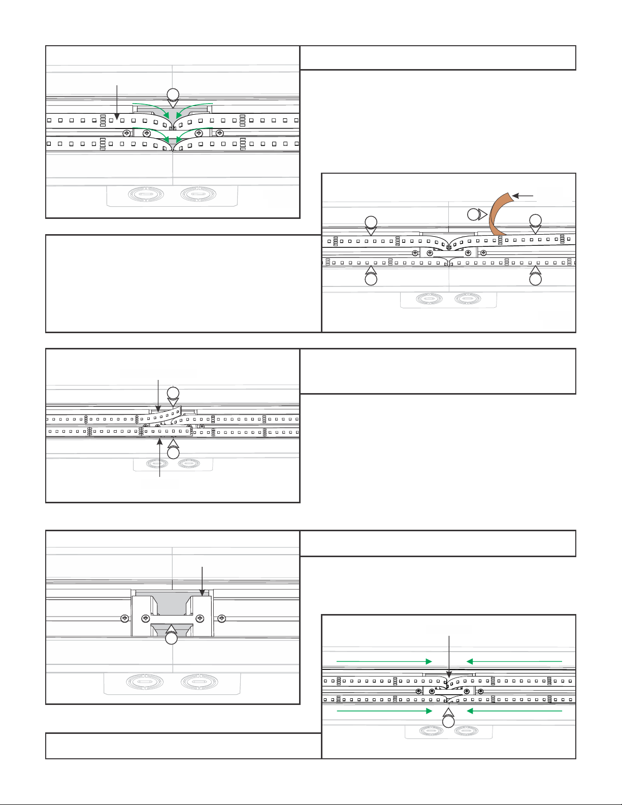
6: Carefully remove the backing from the LED strip, making
sure not to remove the tape from the LED strip. Line up the
red wire side of the power connector with the “+24VDC”
marking on the LED strip. Push the male connector of the
LED strip into the L-Shaped Flexible Power Connector.
7: Firmly press down the adhesive portion of the LED strip onto
the side mount channel surface while removing the rest of
the backing, making sure there are no air bubbles that can
cause surface irregularities.
M
LED
STRIP
PAPER
BACKING
7
6
NOTE: Omit this section if using the Snap & Light connector
(LC-SLC) with Standard Soft Strip. Refer to Section Four.