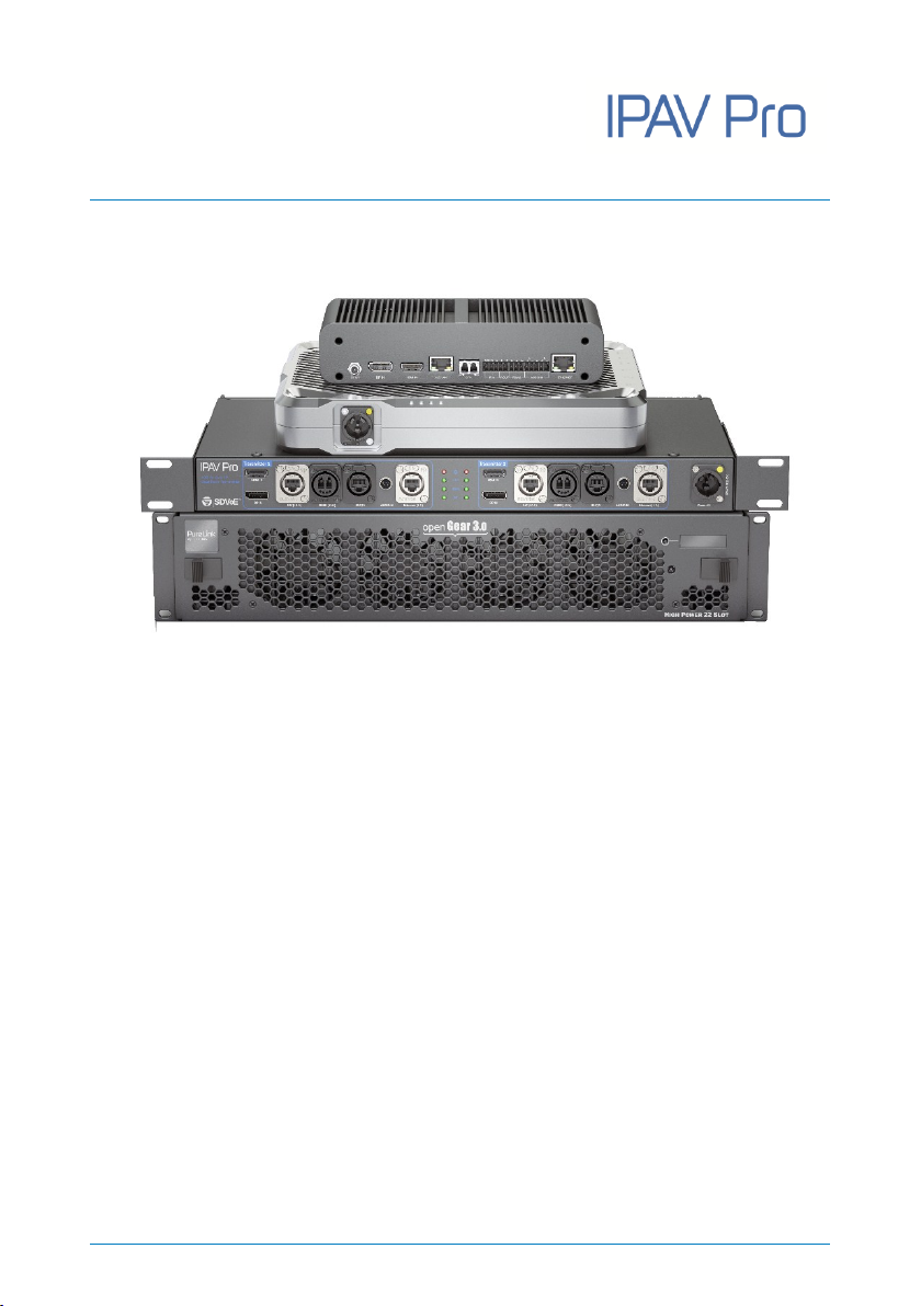
PureLink IPAV Pro Series User manual

User Manual
IPAV Pro Series
User Manual
4K IP Streaming Extender
Model
IPAV1100-TX & IPAV2100-RX
IPAV1000-TX & IPAV2000-RX
IPAV1102-TX
IPAV1200-TX
Designed in Germany
© 2019 PureLink GmbH All rights reserved. V1.1

User Manual
IPAV Pro Series
Preface
Read this user manual carefully before using this product. Pictures shown in this
manual are for reference only. Different model layouts and specifications are subject
to the physical product.
This manual is for operation instructions only, not for any maintenance usage.
In the constant effort to improve our product, we reserve the right to make changes in
functions or parameters without prior notice or obligation.
Trademarks
Product model and logo are trademarks. Any other trademarks mentioned in this
manual are acknowledged as the properties of the trademark owner. No part of this
publication may be copied or reproduced without the prior written consent.
FCC Statement
This equipment generates, uses and can radiate radio frequency energy and, if not
installed and used in accordance with the instructions, may cause harmful
interference to radio communications. It has been tested and found to comply with
the limits for a Class B digital device, pursuant to part 15 of the FCC Rules. These
limits are designed to provide reasonable protection against harmful interference in
a commercial installation.
Operation of this equipment in a residential area is likely to cause interference, in
which case the user at their own expense will be required to take whatever measures
may be necessary to correct the interference.
Any changes or modifications not expressly approved by the manufacture would void
the user’s authority to operate the equipment.

User Manual
IPAV Pro Series
REACH | 1907/2006/EU
ROHS | 2011/65/EU
PureLink hereby declares that this products PureTools IPAV1100-TX & IPAV2100-RX,
IPAV1000-TX&IPAV2000-RX,IPAV1102-TX,IPAV1200-TX complies with Directives
1907/2006/EU und 2011/65/EU.
EMC / LVD (Electro Magnetic Compatibility / Low Voltage Directive)
PureLink GmbH hereby declares that this products PureTools IPAV1100-TX &
IPAV2100-RX, IPAV1000-TX&IPAV2000-RX,IPAV1102-TX,IPAV1200-TX complies
with Directives 2014/30/EU and 2014/35/EU. The full text of the EU Declaration of
Conformity is available at the following Internet address:
IPAV1100-TX: http://www.purelink.de/ce/4251364715994_CE.pdf
IPAV2100-RX: http://www.purelink.de/ce/4251364715987_CE.pdf
IPAV1000-TX: http://www.purelink.de/ce/4251364718148_CE.pdf
IPAV2000-RX: http://www.purelink.de/ce/4251364718179_CE.pdf
IPAV1102-TX: http://www.purelink.de/ce/4251364720066_CE.pdf
IPAV1200-TX: http://www.purelink.de/ce/4251364720073_CE.pdf

User Manual
IPAV Pro Series
SAFETY PRECAUTIONS
To ensure the best from the product, please read all instructions carefully before using
the device. Save this manual for further reference.
Unpack the equipment carefully and save the original box and packing material
for possible future shipment.
Follow basic safety precautions to reduce the risk of fire, electrical shock and
injury to persons.
Do not dismantle the housing or modify the module. It may result in electrical
shock or burn.
Using supplies or parts not meeting the products’ specifications may cause
damage, deterioration or malfunction.
Refer all servicing to qualified service personnel.
To prevent fire or shock hazard, do not expose the unit to rain, moisture or install
this product near water.
Do not put any heavy items on the extension cable in case of extrusion.
Do not remove the housing of the device as opening or removing housing may
expose you to dangerous voltage or other hazards.
Install the device in a place with fine ventilation to avoid damage caused by
overheat.
Keep the module away from liquids.
Spillage into the housing may result in fire, electrical shock, or equipment
damage. If an object or liquid falls or spills on to the housing, unplug the module
immediately.
Do not twist or pull by force ends of the optical cable. It can cause malfunction.
Do not use liquid or aerosol cleaners to clean this unit. Always unplug the power
to the device before cleaning.
Unplug the power cord when left unused for a long period of time.
Information on disposal for scrapped devices: do not burn or mix with general
household waste, please treat them as normal electrical wastes.

User Manual
IPAV Pro Series
Table of Contents
1. Product Introduction ..................................................................................................................1
1.1 About 10G Networks .......................................................................................................1
1.2 Features .............................................................................................................................. 2
1.3 Package List .......................................................................................................................3
2. Specification.................................................................................................................................5
2.1 IPAV1100-TX .....................................................................................................................5
2.2 IPAV2100-RX .....................................................................................................................6
2.3 IPAV1000-TX .....................................................................................................................7
2.4 IPAV2000-RX .....................................................................................................................8
2.5 IPAV1102-TX .....................................................................................................................9
2.6 IPAV1200-TX ...................................................................................................................10
3. Panel Description..................................................................................................................... 11
3.1 IPAV1100-TX ...................................................................................................................11
3.1.1 Back and Side Panel .......................................................................................... 11
3.1.2 Front and Side Panel......................................................................................... 12
3.2 IPAV2100-RX ...................................................................................................................13
3.2.1 Back and Side Panel .......................................................................................... 13
3.2.2 Front and Side Panel......................................................................................... 14
3.3 IPAV1000-TX ...................................................................................................................15
3.3.1 Front Panel .......................................................................................................... 15
3.3.2 Rear Panel............................................................................................................ 16
3.4 IPAV2000-RX ...................................................................................................................17
3.4.1 Front Panel .......................................................................................................... 17
3.4.2 Rear Panel............................................................................................................ 18
3.5 IPAV1102-TX ...................................................................................................................19
3.6 IPAV1200-TX ...................................................................................................................20

User Manual
IPAV Pro Series
3.7 RS232 Pin Definition .....................................................................................................24
3.8 XLR Pin Definition ..........................................................................................................24
4. System Connection.................................................................................................................. 25
4.1 Usage Precaution............................................................................................................25
4.2 System Connection........................................................................................................25
4.3 System Diagram..............................................................................................................26
4.4 Switch Selection .............................................................................................................27
5. Operation of IPAV Pro Control Center................................................................................. 28
5.1 General Information ......................................................................................................28
5.2 Device Configuration ....................................................................................................30
5.3 Start IPAV Pro Control Center......................................................................................32
5.4 Video Routing Tab..........................................................................................................33
5.4.1 Video Switching ................................................................................................. 34
5.4.2 Sending a Single Source to any RX Device.................................................. 35
5.4.3 Stopping/Starting Video .................................................................................. 35
5.4.4 Disconnecting Source from RX....................................................................... 36
5.4.5 Preset Management .......................................................................................... 36
5.5 Video Wall Routing Tab ................................................................................................37
5.5.1 Configuring a Video Wall................................................................................. 38
5.5.2 Preset Management .......................................................................................... 38
5.5.3 Removing RX from Video Wall ....................................................................... 40
5.5.4 Changing Output Resolution for Video Wall Receivers ........................... 41
5.6 HDMI Audio Routing Tab...............................................................................................42
5.7 Analog Audio Routing Tab............................................................................................44
5.8 RS-232 Routing Tab .......................................................................................................46
5.8.1 Assign Transmitter to all Receivers............................................................... 47
5.8.2 Sending RS-232 Data from IPAV Pro Control Center to a Device .......... 47
5.9 Infrared Routing Tab......................................................................................................48
5.9.1 Assign Transmitter to all Receivers............................................................... 50

User Manual
IPAV Pro Series
5.9.2 Sending IR Data from IPAV Pro Control Center to a Device .................... 50
5.10 Global Command Options and Settings .................................................................51
5.10.1 Receiver (RX) Settings Options.................................................................... 51
5.10.2 Transmitter (TX) Settings Options............................................................... 56
5.10.3 Clean Settings forTX and RX......................................................................... 59
5.10.4 Factory Reset.................................................................................................... 60
5.10.5 Backup Settings ............................................................................................... 61
5.10.6 Restore Settings .............................................................................................. 62
5.11 System Management Tab...........................................................................................63
5.11.1 Device Firmware Upgrade............................................................................. 63
5.11.2 System Backup and Restore ......................................................................... 64
5.11.3 Security Settings ............................................................................................. 67
5.11.4 System Logs...................................................................................................... 67
5.12 Routing Table Tab ........................................................................................................68
6. Troubleshooting & Maintenance.......................................................................................... 70
7. After-Sales Service................................................................................................................... 71

User Manual
IPAV Pro Series
1
1. Product Introduction
The IPAV Pro series consists of a network-based AV transmitters and receivers
supporting HDMI and DisplayPort inputs up to 4K, 4:4:4 and incl. HDR. It is designed
for HDMI/DP transmission over IP networks, able to integrate external audio as well
as control signals at distances of up to 100m using a Cat cable or over 300m over
Multi Mode fiber. It can be controlled by one PC with installed control software (IPAV
Pro Control Center) and one 10GbE Switch to control a variety of functions.
The IPAV Pro series provides one of the most advanced IP streaming solutions on the
market utilizing BlueRiver™ NT+ technology, which synergizes various IP/AV
standards to work together as one. Fully compatible with all other SDVoE products on
the market making the Pro Series versatile and cross compatible.
The IPAV Pro series features uncompressed video transmission with zero latency from
transmitter to receiver, seamless switching, video wall functionality, 1G Ethernet
integration, RS232 control, audio embedding & de-embedding, audio down-mixing,
and much more. The control software merges all functions into a single windows
application.
The rugged IPAV Pro housing is custom made to fit the demanding requirements of
rental and staging markets, making this a tough but highly versatile product to suit
multiple professional applications.
1.1 About 10G Networks
Unlike traditional AV extension technology, such as HDBaseT, where transmitters and
receivers are connected point to point or joined together using custom matrix
switches, the IPAV Pro transmitter and receiver units are based on the inter
compatible BlueRiver™ NT+ technology and connected using standard, off the shelf
10G Layer 2/3 network switches.

User Manual
IPAV Pro Series
2
This architecture makes use of data packages that can be easily and independently
routed to the desired unit. A variety of transmission modes are possible this way,
from one transmitter to one receiver (point to point) or one transmitter to many
receivers (point to multipoint) or many transmitters to many receivers (multipoint to
multipoint) as well as software controllable video wall integration.
An added benefit of packet data transmission is that each signal type (video, audio,
RS232, etc.) is routed independently and not necessarily to the same destination. For
example, the HDMI video from a particular transmitter is routed to 4 receivers, while
the audio goes to all receivers in the setup.
This unlimitedly scalable and independent signal routing enables multiple, scalable
applications, including signal extension, splitting, switching, matrixing, and video wall
functionality.
1.2 Features
BlueRiver™ NT+ technology, featuring the NT1000 chipset inside the
transmitter and NT2000 chip with powerful scaling capabilities included in the
receiver.
Streams uncompressed A/V signals with zero latency incl. control signals, with
the flexibility of transmitting them together or to separate network
destinations.
Supports HDMI 2.0 and video resolutions up to 4K @60Hz, 4:4:4, 8bit.
High bandwidth of up to 18Gbps, supporting HDR10 and Dolby Vision.
Automatic detection and switching of HDMI and DisplayPort inputs.
Transmits and receives RS232 to/from any unit in the same system by using
Unicast / Broadcast IPV4 protocols or local API server control.
Full HDCP version support, including v2.2.

User Manual
IPAV Pro Series
3
Allows a video source to be stretched across multiple displays (max. 5x5 video
wall).
Seamless switching between different transmitters with selectable output
resolutions up to 4K incl. receiver-sided scaling ability to fit the display format.
HDMI audio as well as external balanced audio inputs can be routed as an
independent stream to desired receiver devices for balanced audio de-
embedding or down-mixing.
The BlueRiver NT+ chipset is fully compliant with the SDVoE™ standard,
offering zero-latency AV over IP with true 4K @60Hz and powerful precessing
features.
1.3 Package List
Note: Please contact your distributor immediately if any damage or defect in the
components is found.
Model
Package List
IPAV1100-TX
1x IPAV1100-TX Transmitter
1x Power Cord
User Manual
IPAV2100-RX
1x IPAV2100-RX Receiver
1x Power Cord
User Manual

User Manual
IPAV Pro Series
4
Model
Package List
IPAV1000-TX
1x IPAV1000-TX Transmitter
2x Mounting Ears with 6 Screws
4x Plastic Cushions
1x 3-pin Terminal Block
2x 5-pin Terminal Blocks
1x Power Adaptor (12V DC 2A)
1x User Manual
IPAV2000-RX
1x IPAV2000-RX Receiver
2x Mounting Ears with 6 Screws
4x Plastic Cushions
1x 3-pin Terminal Block
2x 5-pin Terminal Blocks
1x Power Adaptor (12V DC 2A)
1x User Manual
IPAV1102-TX
1x IPAV1102-TX Transmitter
2x Mounting Ears with 6 Screws
1x Power Cord
1x User Manual
IPAV1200-TX
IPAV1200-TX Transmitter
1x 3-pin Terminal Block
1x 5-pin Terminal Block
1x User Manual

User Manual
IPAV Pro Series
5
2. Specification
2.1 IPAV1100-TX
IPAV1100-TX
Video Input
(1) HDMI, (1) DP
Video Input Connector
(1) Type-A Female HDMI, (1) DisplayPort
HDMI Input Resolution
Up to 4Kx2K@60Hz 4:4:4 8bit
DP Input Resolution
Up to 4Kx2K@60Hz 4:4:4 8bit
Audio Input
(1) Balanced stereo
Audio Input Connector
(1) 5pin mini XLR
Control
(1) CAT (10G), (1) FIBER (10G), (1) RS232,
(1) ETHERNET (1G)
Control Connector
(2) RJ45, (1) LC, (1) RJ11(6P4C)
General
External Power Supply
220~240V AC, 50/60Hz
Power Consumption
19W (Max)
Operation Temperature
-10℃~ +60℃
Storage Temperature
-25℃~ +70℃
Relative Humility
10%-90%
Dimension (W*H*D)
290mm x 44mm x 240mm
Net Weight
2.88KG

User Manual
IPAV Pro Series
6
2.2 IPAV2100-RX
IPAV2100-RX
Video Output
(1) HDMI
Video Output Connector
(1) Type-A Female HDMI
HDMI Output Resolution
Up to 4Kx2K@60Hz 4:4:4 8bit
Audio Output
(1) Balanced stereo
Audio Output Connector
(1) 5pin mini XLR
Control
(1) CAT (10G), (1) FIBER (10G), (1) RS232,
(1) ETHERNET (1G)
Control Connector
(2) RJ45, (1) LC, (1) RJ11 (6P4C)
General
External Power Supply
220~240V AC, 50/60Hz
Power Consumption
21W (Max)
Operation Temperature
-10℃~ +60℃
Storage Temperature
-25℃~ +70℃
Relative Humility
10%-90%
Dimension (W*H*D)
290mm x 44mm x 240mm
Net Weight
2.86KG

User Manual
IPAV Pro Series
7
2.3 IPAV1000-TX
IPAV1000-TX
Video Input
(1) HDMI, (1) DP
Video Input Connector
(1) Type-A female HDMI, (1) DisplayPort
HDMI Input Resolution
Up to 4Kx2K@60Hz 4:4:4 8bit
DP Input Resolution
Up to 4Kx2K@60Hz 4:4:4 8bit
Audio Input
(1) Balanced Stereo
Audio Input Connector
(1) 5-pin terminal block
Control
(1) 10G LAN, (1) SFP+, (1) IR IN, (1) IR OUT,
(1) RS232, (1) ETHERNET
Control Connector
(2) RJ45, (1) LC, (1) 5-pin terminal blocks,
(1) 3-pin terminal blocks
General
External Power Supply
Input: AC 100~240V, 50/60Hz, Output: 12V DC 2A
Power Consumption
19W (Max)
Operation Temperature
-10℃~ +55℃
Storage Temperature
-25℃~ +70℃
Relative Humility
10%-90%
Dimension (W*H*D)
224.0mm x 49.2mm x 110.0mm
Net Weight
1.16KG

User Manual
IPAV Pro Series
8
2.4 IPAV2000-RX
IPAV2000-RX
Video Output
(1) HDMI
Video Output Connector
(1) Type-A female HDMI
HDMI Output Resolution
Up to 4Kx2K@60Hz 4:4:4 8bit
Audio Output
(1) Balanced Stereo
Audio Output Connector
(1) 5-pin terminal block
Control
(1) 10G LAN, (1) SFP+, (1) IR IN, (1) IR OUT,
(1) RS232, (1) ETHERNET
Control Connector
(2) RJ45, (1) LC, (1) 5-pin terminal blocks,
(1) 3-pin terminal blocks
General
External Power Supply
Input: AC 100~240V, 50/60Hz, Output: 12V DC 2A
Power Consumption
21W (Max)
Operation Temperature
-10℃~ +55℃
Storage Temperature
-25℃~ +70℃
Relative Humility
10%-90%
Dimension (W*H*D)
224.0mm x 49.2mm x 110.0mm
Net Weight
1.19KG

User Manual
IPAV Pro Series
9
2.5 IPAV1102-TX
IPAV1102-TX (Integrated 2 IPAV1100-TX Transmitter Mainboards)
Video Input
(2) HDMI, (2) DP
Video Input Connector
(2) Type-A Female HDMI, (2) DisplayPort
HDMI Input Resolution
Up to 4Kx2K@60Hz 4:4:4 8bit
DP Input Resolution
Up to 4Kx2K@60Hz 4:4:4 8bit
Audio Input
(2) Balanced stereo
Audio Input Connector
(2) 5pin mini XLR
Control
(2) CAT (10G), (2) FIBER (10G), (2) RS232,
(2) ETHERNET (1G)
Control Connector
(4) RJ45, (2) LC, (2) RJ11(6P4C)
General
External Power Supply
220~240V AC, 50/60Hz
Power Consumption
38W (Max)
Operation Temperature
-10℃~ +60℃
Storage Temperature
-25℃~ +70℃
Relative Humility
10%-90%
Dimension (W*H*D)
436.4mm x 44mm x 280mm
Net Weight
3KG

User Manual
IPAV Pro Series
10
2.6 IPAV1200-TX
IPAV1200-TX (OpenGear 4K IP Streaming Card)
Video Input
(1) HDMI
Video Input Connector
(1) Type-A female HDMI
HDMI Input Resolution
Up to 4Kx2K@60Hz 4:4:4 8bit
Audio Input
(1) AUDIO
Audio Input Connector
(1) 5pin mini XLR
Control
(1) CAT (10G), (1) FIBER (10G), (1) RS232, (1) IR IN,
(1) OUT
Control Connector
(2) RJ45, (1) LC, (1) 3-pin terminal block,
(1) 5-pin terminal block
General
External Power Supply
Powered by OG3-FR Series Frame (Sold separately).
Power Consumption
19W (Max)
Operation Temperature
-10℃~ +55℃
Storage Temperature
-25℃~ +70℃
Relative Humility
10%-90%
Dimension (W*H*D)
Front Module: 324m x 77mm x 26mm
Rear Module: 85mm x 33 mm x 30mm
Net Weight
Front Module: 290g,
Rear Module: 25g

User Manual
IPAV Pro Series
11
3. Panel Description
3.1 IPAV1100-TX
3.1.1 Back and Side Panel
①HDMI IN: Type-A female HDMI port for HDMI video source device.
②DP IN: DisplayPort input port for DP video source device.
③CAT (10G): RJ45 port to connect directly to the RX or a network switch using
Cat6a / Cat7.
④FIBER (10G): LC port to connect directly to the RX or a fiber network switch using
an optical LC cable.
⑤RS232: RJ11 (6P4C) port for RS232 control. Supports point to point unicast and
one to all broadcast configurations.
⑥AUDIO IN: A miniXLR (5pin) port to connect a balanced audio source.
⑦ETHERNET (1G): RJ45 port to connect control devices (such as PC) for system
control via software and Ethernet pass-through. The PC can also be indirectly
connected to the network switch.
⑧220~240V AC IN: Rugged D-Type Neutrik powerCON TRUE1 connector for AC
input.
⑨Signal LEDs:
POWER LED: The LED illuminates red when power is applied.
LINK LED: The LED indicates if Ethernet packets are transmitted.
LED off: Packets are not transmitted.
LED blinking: Packets are transmitted.
LED on: packets are not transmitted but link is present.
HDMI LED: The LED illuminates green when the HDMI video source is selected.
DP LED: The LED illuminates green when the DP video source is selected.
123456789

User Manual
IPAV Pro Series
12
3.1.2 Front and Side Panel
①220~240V AC OUT: Rugged D-Type Neutrik powerCON TRUE1 connector for
redundant AC output to cascade multiple units.
②Mounting hole for truss clamp (second one on the bottom side)
12

User Manual
IPAV Pro Series
13
3.2 IPAV2100-RX
3.2.1 Back and Side Panel
①HDMI OUT: Type-A female HDMI port for HDMI display device.
②CAT (10G): RJ45 input to connect directly to the TX or network switch using a
Cat6a / Cat7 cable.
③FIBER (10G): LC port to connect directly to the TX or a fiber network switch using
an optical LC cable.
④RS232: RJ11 (6P4C) port for RS232 control. Supports point to point unicast and
one to all broadcast configurations.
⑤AUDIO OUT: MiniXLR (5pin) port to connect balanced audio playback device.
⑥ETHERNET (1G): RJ45 port to connect control devices (such as PC) for system
control via software and Ethernet pass-through. The PC can also be indirectly
connected to the network switch.
⑦220~240V AC IN: Rugged D-Type Neutrik powerCON TRUE1 connector for AC
input
⑧Signal LEDs:
POWER LED: The LED illuminates red when power is applied.
LINK LED: The LED indicates if Ethernet packets are transmitted.
LED off: Packets are not transmitted.
LED blinking: Packets are transmitted.
LED on: packets are not transmitted but link is present.
HDMI LED: The LED illuminates green when there is HDMI video output.
12345678
This manual suits for next models
6
Table of contents