3
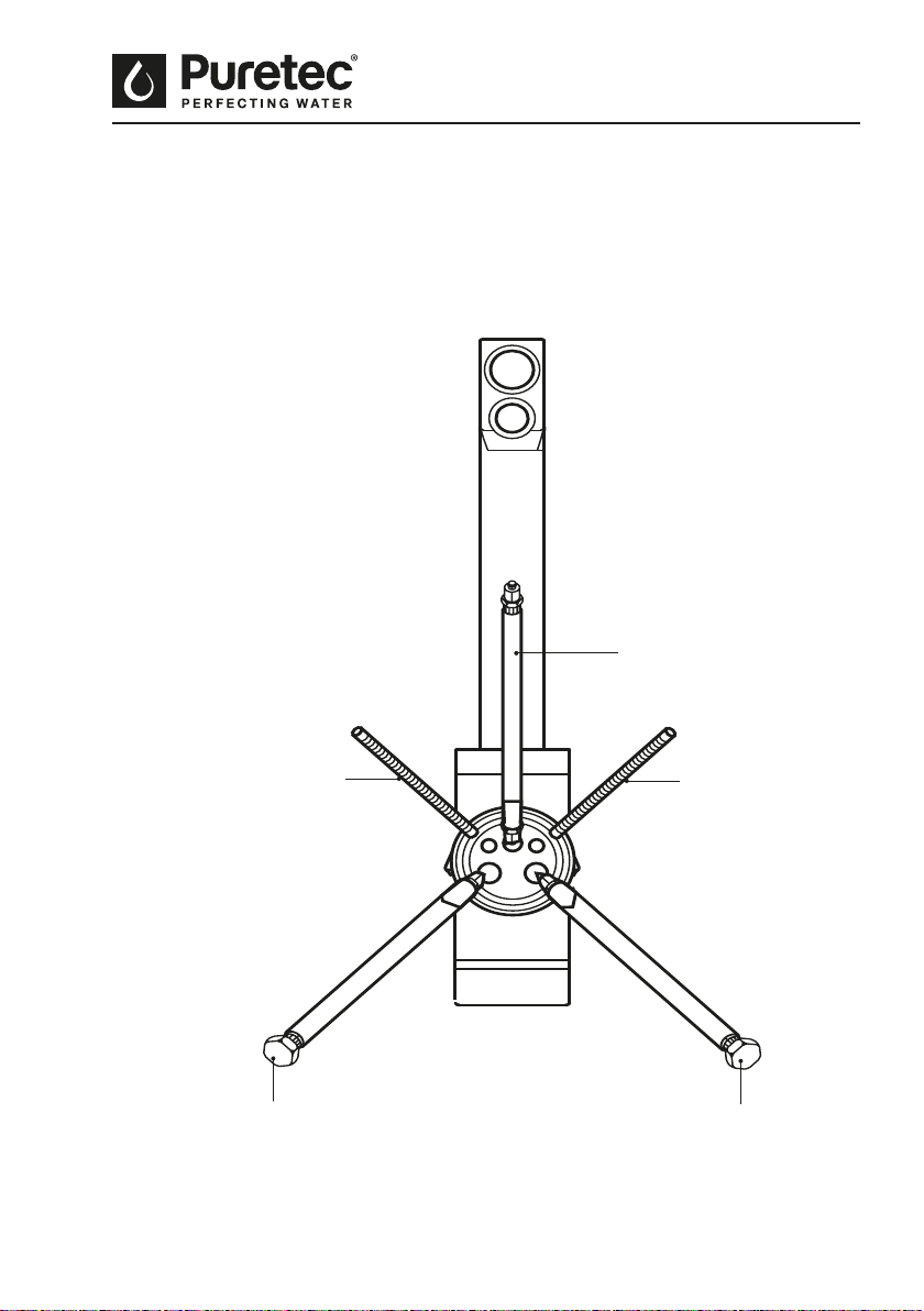
Undersink UV Filter System with Tripla™ LED Mixer Tap
Introduction
The system is designed for rain tank or metropolitan supply water but can be used in other
situations. For other types of water supply please contact your local Puretec stockist or call our
Puretec Customer Service Helpline prior to installing the tap on 1300 140 140 (Australia) 0800
130 140 (New Zealand).
Caution: The eectiveness of any water treatment system is aected by variances in incoming
water quality. Do not use with unknown or contaminated water that does not t the parameters of
the system/product as specied by Puretec, for further assistance, contact the Puretec Customer
Service Helpline on 1300 140 140 (AU) or 0800 130 140 (NZ).
Operation
The Puretec system is designed to run economically for many years, dependent on the initial
installation and periodical maintenance.
Flush systems for 10 minutes aer any period of non-use more than 2 days. For a period of non-
use of 2 weeks or more, it may be necessary to replace cartridges.
Chrome Plated Surface - should only be cleaned with liquid detergent or soap and water. Under no
circumstance should any abrasive or acid base cleaning agents be used.
Installation Note: A water lter system/tap, like any product, has a limited life and may eventually
fail. Also sometimes failure happens early due to unforeseen circumstances. To avoid possible
property damage, this product should be regularly examined for leakage and/or deterioration and
replaced when necessary. A drain pan, plumbed to an appropriate drain or outtted with a leak
detector, should be used in those applications where any leakage could cause property damage,
and/or the water supply should be turned o if no one is home/present.
INSTALLATION SHOULD BE COMPLETED BY QUALIFIED TRADESPEOPLE. FAULTY OPERATION
DUE TO UNQUALIFIED PERSONS WILL RESULT IN VOIDED WARRANTY COVERAGE.
Use Guidelines
• Min/Max operating pressure 300 - 500 kPa.
• Min/Max temperature 0 - 52°C (protect from freezing).
• This system must be installed according to local plumbing codes on the cold water line.
• Puretec recommends the use of a surge protector (not supplied) or warranty
may be voided.
• Do not use long extension leads as they may cause substantial voltage drop
and/or poor lamp performance.
• Be sure to change the lter cartridge at least every 6 - 12 months which ever occurs
rst; or whenever you detect a change in taste, odour, or decrease in ow.
• UV Lamps must be replaced annually in order to maintain 99.9% kill rate of bacteria.